
High Gain SIW H-Plane Horn Antenna with 3D Printed Parasitic E-Plane Horn


Abstract
:1. Introduction
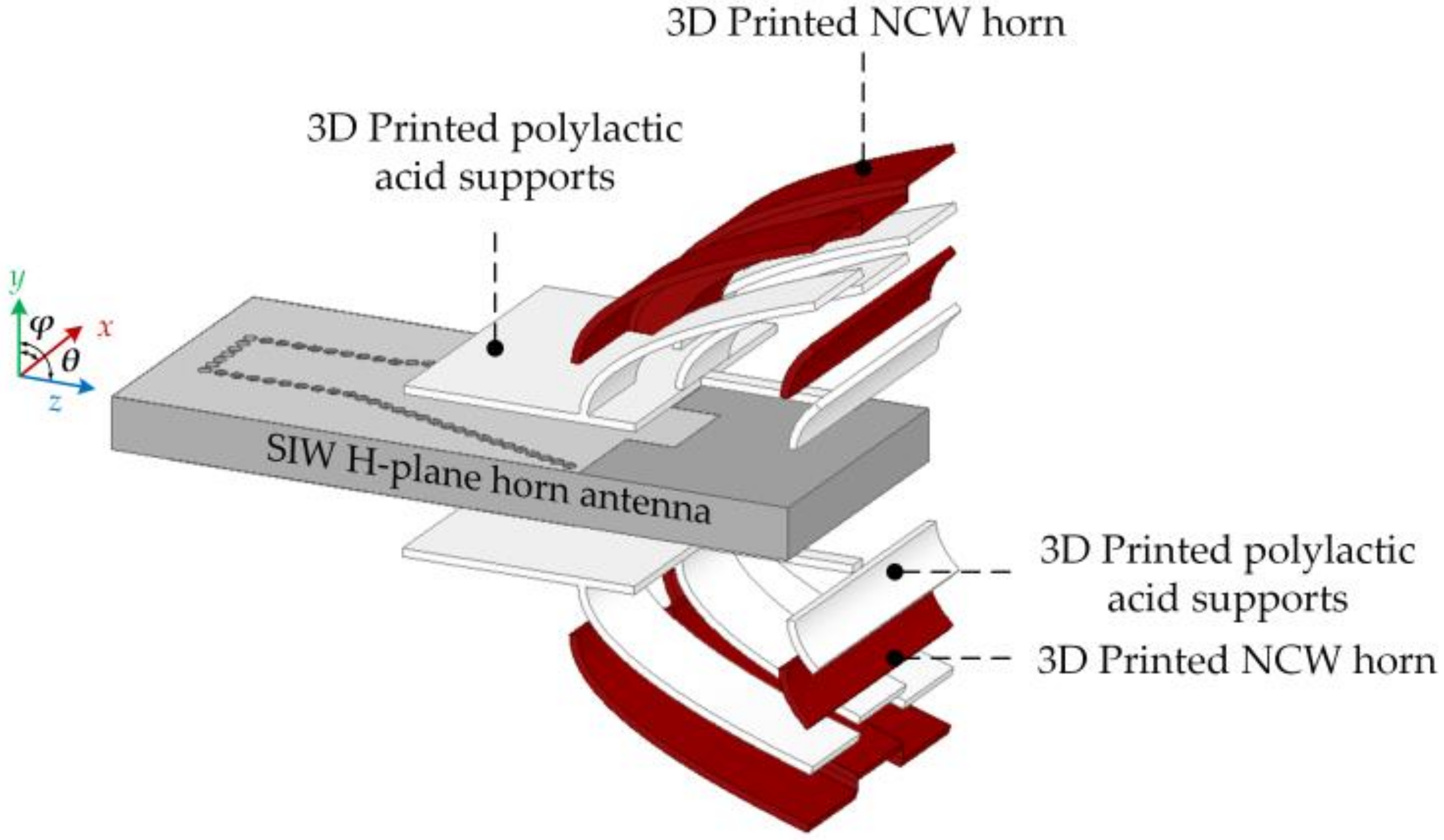
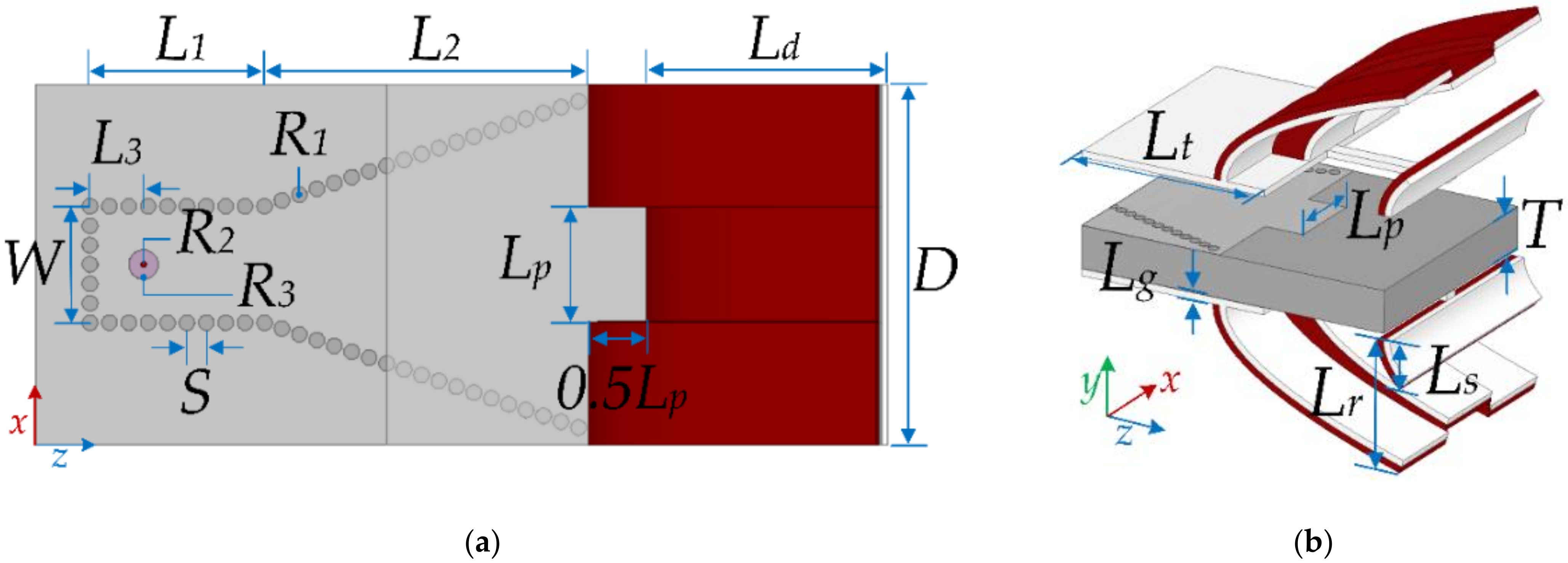
2. Antenna Design
3. The Improvements by the 3D Printed Horns
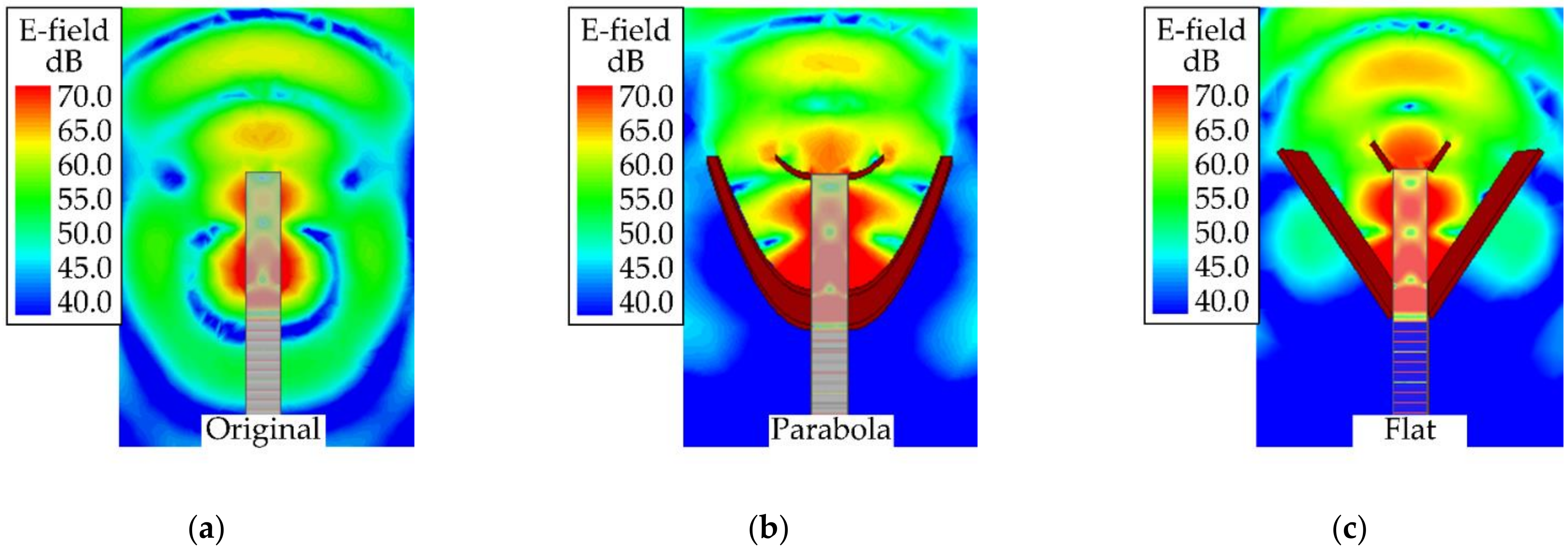
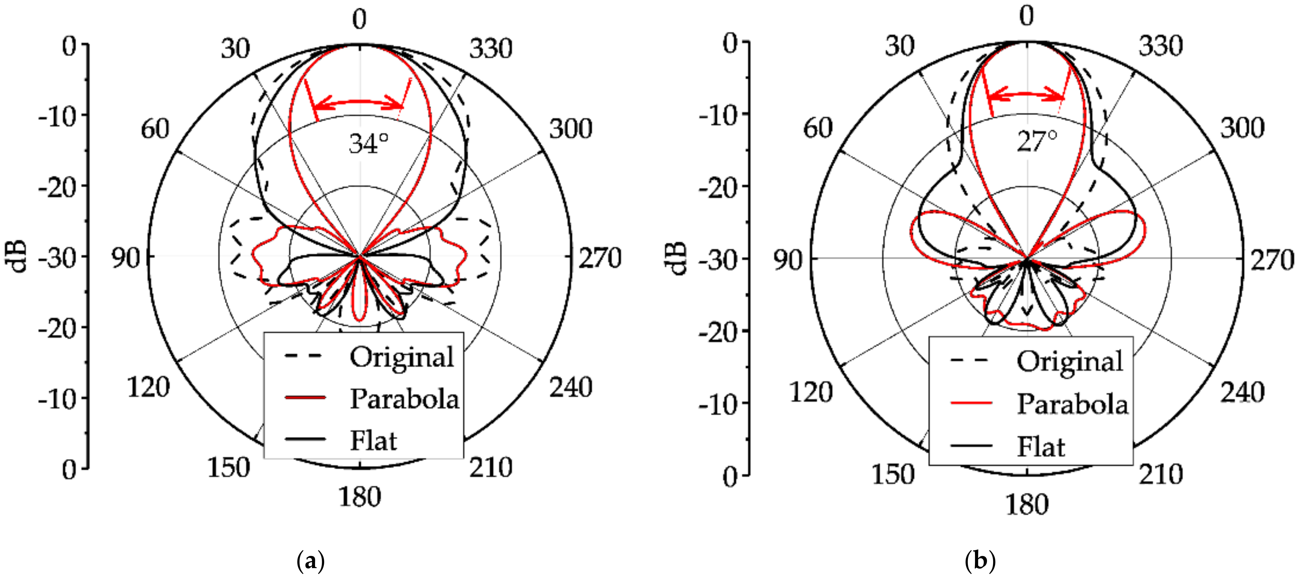
3.1. Comparative Field Analysis
3.2. The Impact of the 3D Print Materials
3.2.1. The Nano Copper Wire (NCW) Based Conductors
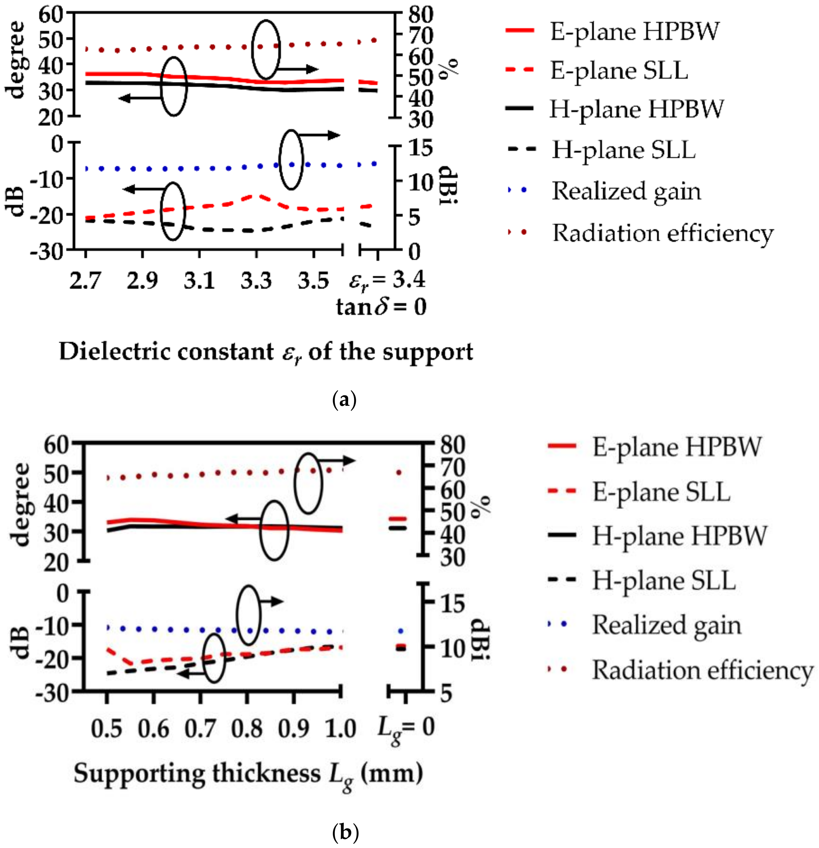
3.2.2. The Polylactic Acid (PLA) Dielectric
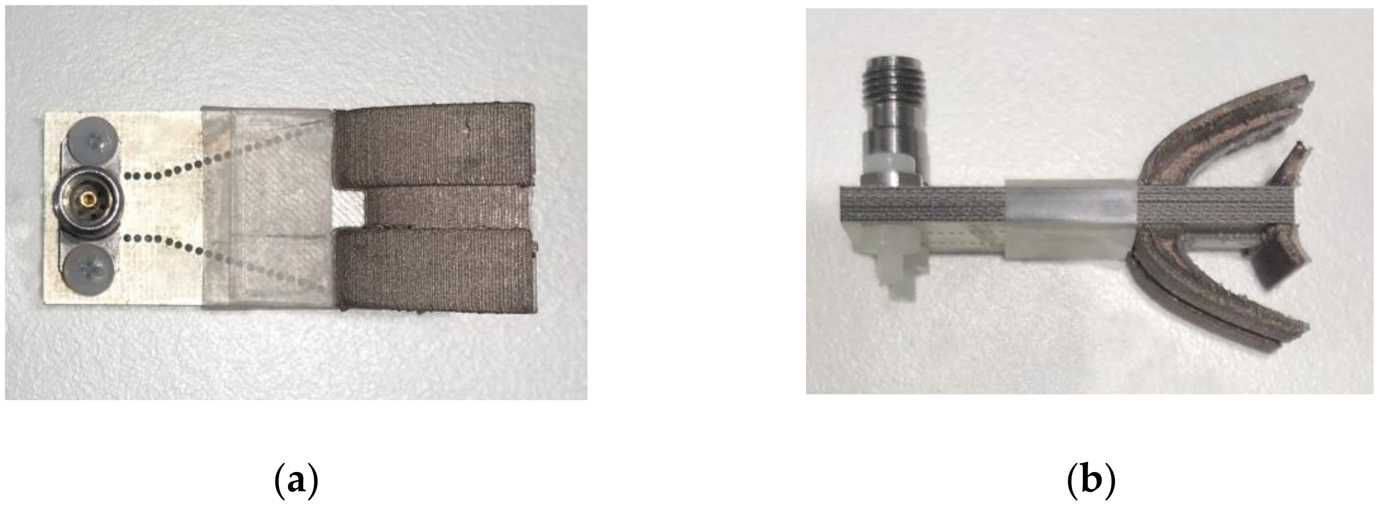
4. Antenna Fabrication and Measurement
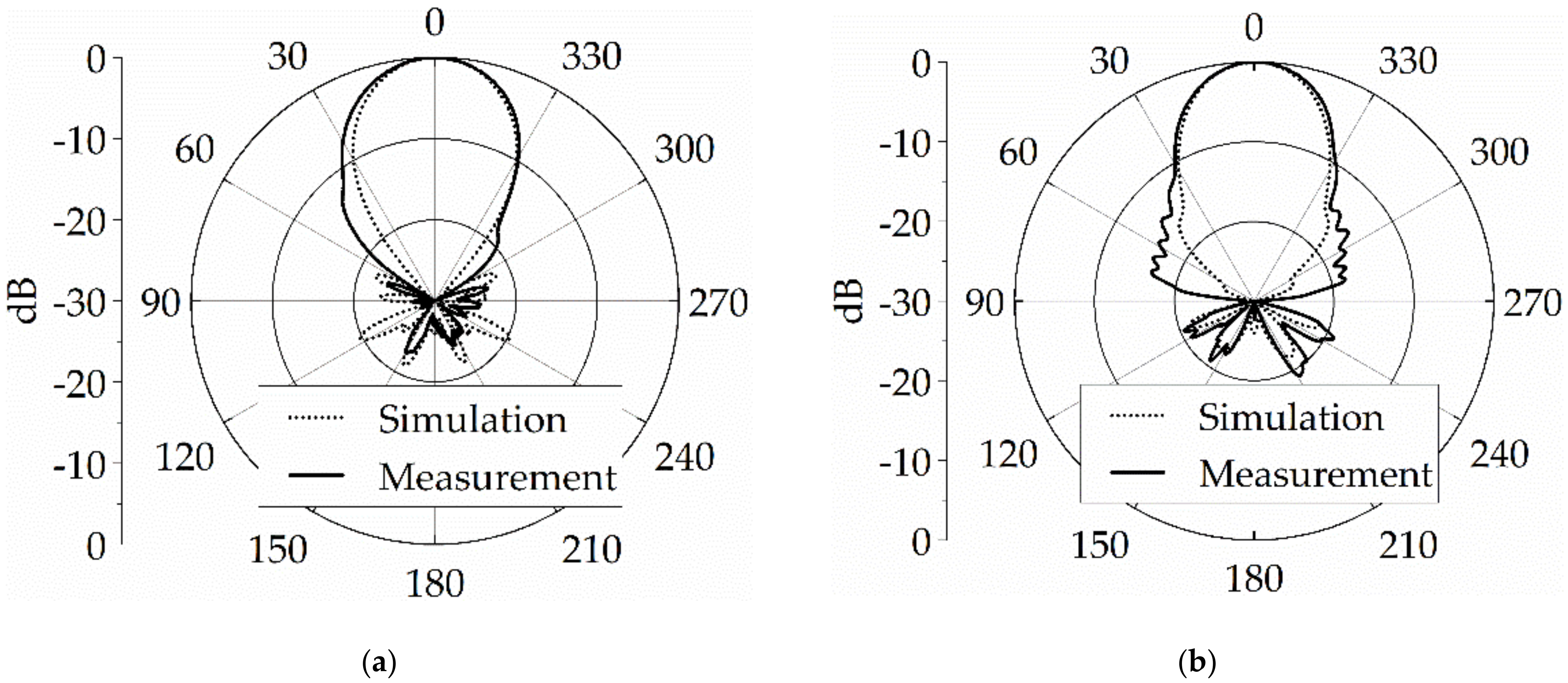
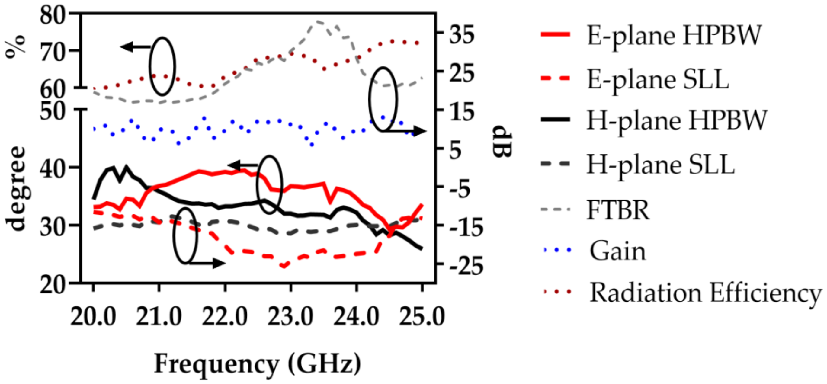
4.1. The Radiation Characteristics
4.2. The Reflection Coefficient |S11|
5. Discussion
6. Conclusions
Author Contributions
Funding
Data Availability Statement
Acknowledgments
Conflicts of Interest
References
- Bozzi, M.; Georgiadis, A.; Wu, K. Review of substrate-integrated waveguide circuits and antennas. IET Microw. Antennas Propag. 2011, 5, 909–920. [Google Scholar] [CrossRef]
- Althuwayb, A.A. MTM- and SIW-Inspired Bowtie Antenna Loaded with AMC for 5G mm-Wave Applications. Int. J. Antennas Propag. 2021, 2021, 6658819. [Google Scholar] [CrossRef]
- Yang, Y.; Cai, Y.; Chan, K.Y.; Ramer, R.; Guo, Y.J. MEMS-loaded millimeter wave frequency reconfigurable quasi-Yagi dipole antenna. Asia-Pac. Microw. Conf. Proc. APMC 2011, 1318–1321, 6174002. [Google Scholar]
- Chan, K.Y.; Daneshmand, M.; Mansour, R.R.; Ramer, R. Novel beam design for compact RF MEMS series switches. Asia-Pac. Microw. Conf. Proc. APMC 2007, 1257, 4554572. [Google Scholar]
- Afzal, M.U.; Matekovits, L.; Esselle, K.P.; Lalbakhsh, A. Beam-Scanning Antenna Based on Near-Electric Field Phase Transformation and Refraction of Electromagnetic Wave Through Dielectric Structures. IEEE Access 2020, 8, 199242–199253. [Google Scholar] [CrossRef]
- Althuwayb, A.A. Enhanced radiation gain and efficiency of a metamaterial inspired wideband microstrip antenna using substrate integrated waveguide technology for sub-6 GHz wireless communication systems. Microw. Opt. Technol. Lett. 2021, 63, 1892–1898. [Google Scholar] [CrossRef]
- Dong, Y.; Itoh, T. Miniaturized substrate integrated waveguide slot antennas based on negative order resonance. IEEE Trans. Antennas Propag. 2010, 58, 3856–3864. [Google Scholar] [CrossRef]
- Gu, Z.; Wu, X.H.; Zhang, Q. Substrate-integrated E-plane waveguide horn antenna and antenna array. IEEE Trans. Antennas Propag. 2018, 66, 2382–2391. [Google Scholar] [CrossRef]
- Bayat-Makou, N.; Kishk, A.A. Substrate integrated horn antenna with uniform aperture distribution. IEEE Trans. Antennas Propag. 2017, 65, 514–520. [Google Scholar] [CrossRef]
- Wang, H.; Fang, D.G.; Zhang, B.; Che, W.Q. Dielectric loaded substrate integrated waveguide (SIW) H-plane horn antennas. IEEE Trans. Antennas Propag. 2010, 58, 640–647. [Google Scholar] [CrossRef]
- Gong, L.; Chan, K.Y.; Ramer, R. Substrate Integrated Waveguide H-Plane Horn Antenna with Improved Front-to-Back Ratio and Reduced Sidelobe Level. IEEE Antennas Wireless Propag. Lett. 2016, 15, 1835–1938. [Google Scholar] [CrossRef]
- Iigusa, K.; Li, K.; Sato, K.; Harada, H. Gain Enhancement of H-Plane Sectoral Post-Wall Horn Antenna by Connecting Tapered Slots for Millimeter-Wave Communication. IEEE Trans. Antennas Propag. 2012, 60, 5548–5556. [Google Scholar] [CrossRef]
- Jamshidi-Zarmehri, H.; Neshati, M.H. Design and Development of High-Gain SIW H-Plane Horn Antenna Loaded With Waveguide, Dipole Array, and Reflector Nails Using Thin Substrate. IEEE Trans. Antennas Propag. 2019, 67, 2813–2818. [Google Scholar] [CrossRef]
- Esquius-Morote, M.; Fuchs, B.; Zurcher, J.; Mosig, J.R. Novel thin and compact H-plane SIW horn antenna. IEEE Trans. Antennas Propag. 2013, 61, 2911–2920. [Google Scholar] [CrossRef] [Green Version]
- Huang, S.; Chan, K.Y.; Fu, Y.; Ramer, R. Dielectric-loaded substrate integrated waveguide H-plane horn antenna with embedded air cavity. IET Microw. Antennas Propag. 2021, 15, 154–162. [Google Scholar] [CrossRef]
- Huang, S.; Chan, K.Y.; Ramer, R. Dielectric-Loaded SIW H-Plane Horn Antenna With Gradient Air Slots. IEEE Antennas Wirel. Propag. Lett. 2020, 20, 43–47. [Google Scholar] [CrossRef]
- Chan, K.Y.; Ramer, R.; Sorrentino, R. Low-Cost Ku-Band Waveguide Devices Using 3-D Printing and Liquid Metal Filling. IEEE Trans. Microw. Theory Tech. 2018, 66, 3993–4001. [Google Scholar] [CrossRef]
- Bi, Y.; Li, Y.; Wang, J. 3D-Printed Wideband Cassegrain Antenna with a Concave Sub-Reflector for 5G Millimeter-Wave Two-Dimensional Multibeam Applications. IEEE Trans. Antennas Propag. 2020, 68, 4362–4371. [Google Scholar] [CrossRef]
- Li, Y.; Lei, G.; Wang, J.; Da, S.; Cao, D.; Wang, J.; Liu, Y. 3-D printed high-gain wideband waveguide fed horn antenna arrays for millimeter-wave applications. IEEE Trans. Antennas Propag. 2019, 67, 2868–2877. [Google Scholar] [CrossRef]
- Wang, K.X.; Wong, H. A wideband millimeter-wave circularly polarized antenna with 3-D printed polarizer. IEEE Trans. Antennas Propag. 2017, 65, 1038–1046. [Google Scholar] [CrossRef]
- Kordiboroujeni, Z.; Bornemann, J. Designing the width of substrate integrated waveguide structures. IEEE Microw. Wirel. Compon. Lett. 2013, 23, 518–520. [Google Scholar] [CrossRef]
- Xu, F.; Wu, K. Guided-wave and leakage characteristics of substrate integrated waveguide. IEEE Trans. Microw. Theory Techn. 2005, 53, 66–73. [Google Scholar]
- Balanis, C.A. Antenna Theory: Analysis and Design, 4th ed.; John Wiley & Sons: Hoboken, NJ, USA, 2016; ISBN 978-1118642061. [Google Scholar]
- Luo, Y.; Bornemann, J. Substrate integrated waveguide horn antenna on thin substrate with back-lobe suppression and its application to arrays. IEEE Antennas Wireless Propag. Lett. 2017, 16, 2622–2625. [Google Scholar] [CrossRef]
- Felício, J.M.; Fernandes, C.A.; Costa, J.R. Complex permittivity and anisotropy measurement of 3D-printed PLA at microwaves and millimeter-waves. In Proceedings of the 22nd International Conference on Applied Electromagnetics and Communications (ICECOM), Dubrovnik, Croatia, 15 September 2016. [Google Scholar]
- Huber, E.; Mirzaee, M.; Bjorgaard, J.; Hoyackm, M.; Noghanian, S.; Chang, I. Dielectric property measurement of PLA. In Proceedings of the IEEE International Conference on Electro Information Technology (EIT), Grand Forks, ND, USA, 7 May 2016. [Google Scholar]
- Adibelli, S.; Juyal, P.; Zajic, A. On the Surface Roughness and Smoothing in the 3D Printed THz Reflectors. IEEE Int. Symp. Antennas Propag. USNC-URSI Radio Sci. Meet. 2019, 15, 593–594. [Google Scholar]
- Sung-Uk, Z.; Jonghyeuk, H.; Hyun-Wook, K.; Byoung-Chul, S. Thermo-mechanical properties of ABS parts fabricated by fused deposition modeling and vapor smoothing. Int. Conf. Therm. Mech. Multi-Phys. Simul. Exp. Microelectron. Microsyst. 2017, 6, 7926222. [Google Scholar]
- Cai, Y.; Qian, Z.; Zhang, Y.S.; Cao, W.Q. A compact wideband SIW-fed dielectric antenna with end-fire radiation pattern. IEEE Trans. Antennas Propag. 2016, 64, 1502–1507. [Google Scholar] [CrossRef]
- Park, W.B.; Lee, J.M.; Lee, S.; Park, Y.M.; Hwang, K.C. A 18–40 GHz Substrate Integrated Waveguide H-Plane Horn Antenna. IEEE Trans. Antennas Propag. 2018, 66, 6322–6327. [Google Scholar] [CrossRef]
- Wang, L.; Yin, X.X.; Li, S.L.; Zhao, H.X.; Liu, L.L.; Zhang, M. Phase corrected substrate integrated waveguide h-plane horn antenna with embedded metal-via arrays. IEEE Trans. Antennas Propag. 2014, 62, 1854–1861. [Google Scholar] [CrossRef]
- Cai, Y.; Qian, Z.P.; Zhang, Y.S.; Jin, J.; Cao, W.Q. Bandwidth enhancement of SIW horn antenna loaded with air-via perforated dielectric slab. IEEE Antennas Wirel. Propag. Lett. 2014, 13, 571–574. [Google Scholar]


| Antenna Part | Symbol | Value | Symbol | Value |
|---|---|---|---|---|
| SIW H-plane horn | L1 | 9 | R1 | 0.4 |
| L2 | 17.2 | W | 6 | |
| L3 | 2.76 | S | 1 | |
| Dielectric loading and feeding | Ld | 10 | R2 | 0.15 |
| Lp | 6 | R3 | 0.76 | |
| T | 3.15 | |||
| Printed parasitic horn | Lr | 9 | Lg | 0.5 |
| Ls | 3 | D | 18.6 | |
| Lt | 13.5 |
| Parameters | [10] | [11] | [13] | [14] | [24] | [29] | [30] | [31] | [32] | This Work | ||
|---|---|---|---|---|---|---|---|---|---|---|---|---|
| Frequency (GHz) | 27 | 22.7 | 20.5 | 14.8 | 12.3 | 26.7 | 40 | 35.5 | 24 | 22.7 | ||
| Gain (dBi) | 8.83 | 10.9 | 14 | 7.1 | 10.4 | 9 | 15.4 | 7.87 | 8 | 12 | ||
| FTBR (dB) | 27 | 22 | 24 | 15 | 21.6 * | 22 * | N. A | 15 * | 20 * | 27.8 | ||
| HPBW (°) | E | 80 | 52 | 44 | 160 * | 140 * | 35 * | 29.1 | 29.1 | 40 * | 35 | |
| H | 60 | 30 | 32 | 45 | 40 | 29.6 | 19.5 | 19.5 | 28 * | 33.2 | ||
| SLL (dB) | E | −10 * | −10 * | −10 * | N. A | −5 * | −4 * | −8 * | −8 * | −4 * | −23 | |
| H | −11 * | −15.6 | −20 | −20 | −13 | −9.53 | −15 * | −15 * | −10 * | −15 | ||
| εr of PCB | 4.8 | 5.1 | 2.2 | 3.27 | 6.15 | 4.4 | 2.2 | 3.0 | 4.8 | 5.1 | ||
| Technique on feeding | Coaxial pin | Coaxial pin | Coaxial pin | Reflector, coaxial pin | Coaxial pin | Waveguide | Waveguide | Microstrip line | Waveguide | Coaxial pin | Waveguide | |
| BW (%) | 2.6 * | 2 | 5 | 16 | 0.6 | 34 | K and Ka | 7.6 * | 40 * | 5.3 | 15.3 | |
| Antenna size (λ0) | 2.61 × 0.90 × 0.23 | 3.18 × 1.41 × 0.24 | 2.27 × 1.53 × 0.59 | 1.55 × 0.91 × 0.09 | 1.52 × 0.94 × 0.10 | 7.56 × 0.94 × 0.38 | 7.07 × 2.93 × 0.18 | 3.47 × 1.89 × 0.18 | 9.60 × 1.90 × 0.38 | 2.97 × 1.41 × 1.64 | ||
Publisher’s Note: MDPI stays neutral with regard to jurisdictional claims in published maps and institutional affiliations. |
© 2021 by the authors. Licensee MDPI, Basel, Switzerland. This article is an open access article distributed under the terms and conditions of the Creative Commons Attribution (CC BY) license (https://creativecommons.org/licenses/by/4.0/).
Share and Cite
Huang, S.; Chan, K.Y.; Wang, Y.; Ramer, R. High Gain SIW H-Plane Horn Antenna with 3D Printed Parasitic E-Plane Horn. Electronics 2021, 10, 2391. https://doi.org/10.3390/electronics10192391
Huang S, Chan KY, Wang Y, Ramer R. High Gain SIW H-Plane Horn Antenna with 3D Printed Parasitic E-Plane Horn. Electronics. 2021; 10(19):2391. https://doi.org/10.3390/electronics10192391
Chicago/Turabian StyleHuang, Sheng, King Yuk Chan, Yu Wang, and Rodica Ramer. 2021. "High Gain SIW H-Plane Horn Antenna with 3D Printed Parasitic E-Plane Horn" Electronics 10, no. 19: 2391. https://doi.org/10.3390/electronics10192391
APA StyleHuang, S., Chan, K. Y., Wang, Y., & Ramer, R. (2021). High Gain SIW H-Plane Horn Antenna with 3D Printed Parasitic E-Plane Horn. Electronics, 10(19), 2391. https://doi.org/10.3390/electronics10192391