1. Introduction
Autonomous vehicles have progressively increased their market share. Although the market withered by approximately 3% in 2020 due to the economic recession caused by the COVID-19 pandemic, the market is expected to grow by almost 60% during the forecasted period, 2021–2023 [
1]. In 2030, almost 60% of all new cars will have Level 2 autonomy and they are expected to dominate the market. In addition, approximately 8% of all new cars will have Level 3 and Level 4 systems. However, despite the efforts made by many researches, auto manufacturers, and leading institutes in autonomous vehicle technology, a truly autonomous vehicle still does not exist. One of the main key issues is reliability. Autonomous technologies, such as environment perception, control, and decision, still face many practical challenges, especially in complex traffic scenes or tasks or in adverse weather conditions.
According to NHTSA statistics [
2], 28,190 people died in motor vehicle crashes in the first nine months of 2020. Almost 94% of serious crashes were attributed to driver negligence, such as sleepiness, panic, inexperience, and human reaction time, especially when drivers intended to perform lane changes or to overtake another vehicle, which were the most likely causes of accidents. Moreover, several studies [
3,
4,
5,
6] have emphasized that an overtaking operation leads to fatal car accidents because of the lack of skills, roadway capacities, and information processing abilities. Almost 75% of road traffic accidents are caused by lateral maneuvers involving a driver’s failure to identify hazards. Thus, developing and implementing automated overtaking systems are necessary to reduce human error and can potentially save lives and efficiently reduce injuries. In the development of automated driving technology, overtaking is one of the most difficult and complex functions for the deployment of autonomous driving technologies because of the dynamic and complicated task involved in steering and speed control. Automation of the overtaking maneuver not only requires high precision environment perception technologies to monitor the surrounding traffic conditions but also predicts potential time-critical decision making and action implementation. Autonomous or semi-autonomous vehicles must be able to handle several complex driving maneuvers, such as lane keeping, lane changing, and overtaking, which are required in typical driving situations and can increase road efficiency, especially on single- and two-lane roads.
In the past decades, autonomous vehicles have attracted large interest in the research spotlight of giant companies such as Apple, Uber, and Google [
7]. According to the literature, the first automatic steering wheel was manufactured by Prof. Tsugawa [
8] in Japan in 1977 as part of the “Integrated Automotive Traffic Control System” project. In addition, several lateral controllers have also been developed for advanced transit and highway programs [
9,
10,
11]. However, the aforementioned studies did not provide an advanced ability in their research, e.g., an overtaking system. A completely autonomous car with an overtaking ability can be classified into two functions: overtaking and lane-following functions. Recently, many studies have focused on the overtaking system. Liu et al. [
12] analyzed the features that affect the autonomous lane change using the lane change benefit, safety, and tolerance model. Mehmood et al. [
13] mainly focused on developing a decision design for overtaking trajectory planning and tracking. However, they did not consider a real-vehicle control design, such as throttle and steering control. Zhu et al. [
14] proposed a single neuron PID tracking control strategy for overtaking. As their work did not consider the velocity change in the approaching vehicle, their overtaking maneuver failed when the approaching vehicle accelerated during the overtaking process. Petrov et al. [
15] considered the problem of three-phase overtaking without using the information obtained from road infrastructure or Internet of Vehicle communication. During the overtaking maneuver, they assumed the conditions that the vehicle being overtaken moved along a rectilinear route. However, the overtaken vehicle could be approaching the ego vehicle. Wang et al. [
16] mainly focused on the control process of intelligently connected vehicles that could automatically change lanes. Their automatic lane changing decision model was designed based on the minimum safety distance. They used a fifth-order polynomial as a lane change trajectory and tracked it using the sliding mode control. Chiang et al. [
17] employed fuzzy control in the steering and speed automation to emulate the driving tasks performed by humans. However, the reference trajectory in the overtaking maneuver did not depend on the velocity of the vehicle to be overtaken but only considered the point of initiating a diversion. The abovementioned studies did not comprehensively consider all possible scenarios during the overtaking maneuver.
In addition, various studies have attempted to design an advanced control strategy for lane changes or overtaking maneuver in recent years. The model predictive control (MPC) scheme has attracted increased attention in recent years owing to its ability to systematically handle system constraints and nonlinearities. For example, a lane change motion planning scheme that uses MPC as well as combined steering and braking control has also been proposed [
18,
19,
20,
21,
22]. In [
19], to track the planned overtaking trajectory, the proposed controller formulated the tracking task to a multi-constrain MPC issue and evaluated the steering angle to prevent the vehicle from colliding with a moving vehicle. However, simplified vehicle dynamic models were often considered, which caused the loss of some vehicle dynamic factors such as yaw angle and yaw rate because of the conversion from non-holonomic into holonomic systems. Moreover, although the optimization problem can be calculated in real time, omitting the key dynamic factors causes a difference between the motion planning and actual vehicle motion. Therefore, a nonlinear MPC has been widely applied for collision avoidance and motion planning [
23,
24,
25,
26,
27,
28,
29] owing to its ability to handle nonlinear constraints and to consider a nonlinear vehicle dynamic model. Although nonlinear MPC can handle nonlinear dynamic systems, it requires an iterative solution of optimal control problems on a finite prediction horizon. Hence, the theoretical complexity along with computational requirements, such as the first derivatives of the objective function with respect to the control inputs, are common challenges that hinder the widespread application of the nonlinear MPC. To enhance safety and to improve control efficiency, a legible MPC approach [
24] is developed for overtaking autonomous vehicles on highways. In addition, a robust MPC scheme is proposed to deal with systems with uncertainties as a deterministic and bound set for autonomous vehicle control systems [
26,
27]. Although these methods can increase robustness and efficiency, they tend to be overly conservative or difficult to implement for application in all scenarios. A stochastic MPC is employed to deal with the overtaking maneuvers on country roads using probabilistic traffic predictions [
28]. In addition, the behavior of the surrounding vehicles is stochastically predicted using Bayesian networks. However, these previous studies were only limited to theoretical development and simulation.
The main purpose of a safe overtaking maneuver is to pass an approaching, slower-moving vehicle on a two-way lane. However, the most important key factors for safe overtaking maneuvers include timing of overtaking maintaining a safe distance from the leading vehicle to be overtaken, and safely returning to the original lane or maintaining a safe headway from the vehicle ahead when overtaking maneuver cannot be performed. Consequently, such systems require the capability to assess the current traffic situation, especially on lane information, to determine whether overtaking is possible, thereby managing the speed and steering of the ego vehicle. To derive the lane information, the lane detection scheme is typically used to localize the lane boundaries in the given road images from a front view camera. Most of the existing lane detection methods are designed for advanced driver assistance systems (ADASs), such as lane departure warning systems (LDWs) or lane departure prevention systems (LDPs) [
30]. Generally, the lateral distance to line crossing (DLC), i.e., lateral deviation from the lane border, to a lane boundary is used as a warning criterion. However, if a vehicle runs parallel to the lane lines, DLC goes to infinity, thereby causing false alarms. Therefore, a more accurate judgment criterion such as the time to lane crossing (TLC) [
31,
32,
33] is proposed to predict the time duration available for the driver before the lane boundary crossing. This method can allow for a reaction time to correcting the steering wheel before performing any dangerous driving maneuver. Hence, the TLC information is utilized to predict when a vehicle departs from the current lane, which is referred to as the basis for steering control in the present study.
The present study integrates the advantage and mitigates the disadvantages of the abovementioned work. We utilize TLC to predict when a vehicle can depart the current lane and refer to it as the condition for lane following control. We can effectively adjust the steering wheel before the lane boundary crossing. In addition, we design a control strategy for an overtaking system to predict the optimal steering angle and throttle using successive linearization-based MPC. We consider the safety constraint such as the area for collision-free path to enhance the influence of the controller and to comprehensively take into account all possible scenarios during the overtaking maneuver. Finally, a completely autonomous car with overtaking ability is implemented using an electrical golf car via controller area network (CAN) bus communication. The results demonstrate that the proposed control approach based on TLC and MPC for the intelligent overtaking system is successfully implemented to guarantee driving safety. The main contributions of this research task are summarized as follows:
An image-based TLC strategy is utilized to predict when a vehicle departs from the current lane and refers to it as the condition for lane following control and then automatically adjusts the steering to maintain proper travel inside the lane for implementing the lane-following function. A reaction time can allow for time to correct the steering wheel before a dangerous driving maneuver occurs. When the risk of lane departure is high, the TLC immediately adjusts the steering wheel to ensure that the ego vehicle remains within the lane.
A successive linearization-based model predictive controller that updates the constraints and a predictive plant model at each time step and then is successfully implemented in the vehicle control units (VCU) of our built golf car is proposed.
An electric golf car with CAN bus communication is applied to realize the proposed strategy, and then, real-world experiments successfully verify the proposed autonomous overtaking system.
2. System Description
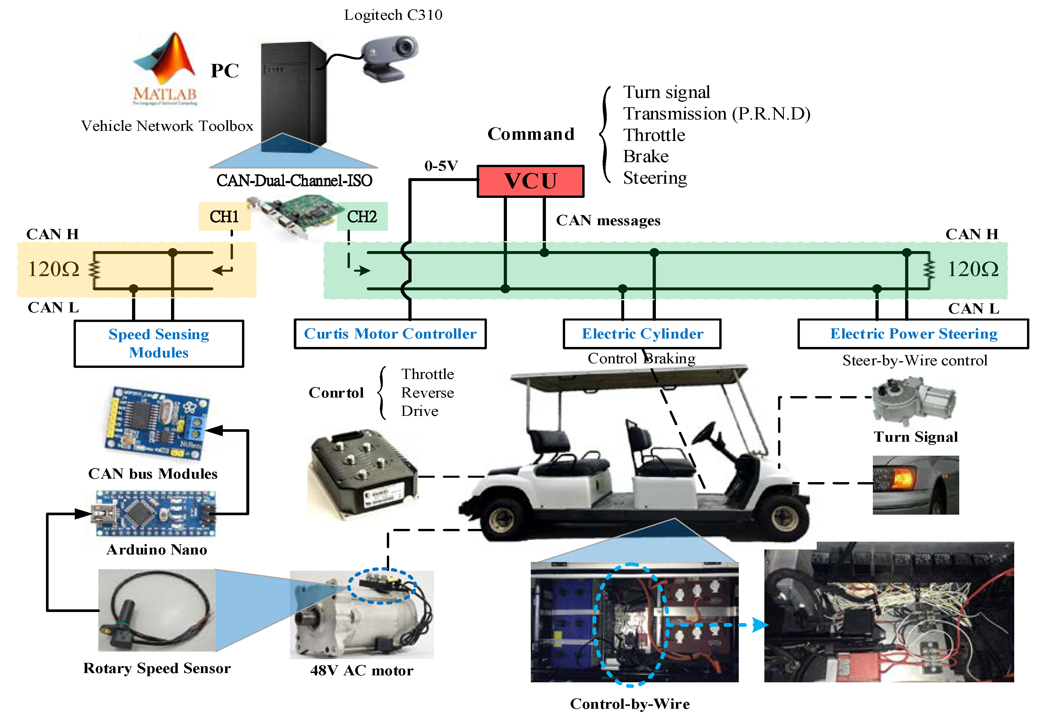
An electric golf car is used to implement the proposed autonomous overtaking system, and the system configuration of the test vehicle is shown in
Figure 1.
The proposed autonomous overtaking system is composed of three functional modules: perception, overtaking decision making, and vehicle control. The architecture of the proposed autonomous overtaking system is shown in
Figure 2. The upper processing steps are environment perception, which relies on the lane lines, and precedes vehicle detection from visual observation. Perception provides information on the distance between the ego and an approaching vehicle, the position of the surrounding vehicles, and the lane lines.
According to the perception information, the overtaking decision-making module based on TLC computation and safe distance estimation are then used to determine whether the vehicle can overtake another vehicle. Next, the lower processing consists of the vehicle control module, which includes two functions: lane following and overtaking functions. Once the decision-making module determines that overtaking is impossible at the moment, the lane-following function is activated. The vehicle steering control based on attitude and velocity of the host vehicle and the TLC information are provided to keep the vehicle within its lane, to center the car within the lane, and to prevent the ego vehicle from unintentional lane departure. On the other hand, in the overtaking function, a successive linearization-based MPC strategy is applied to optimize the steering angle and throttle to overtake a slower vehicle (which is required to keep the minimal safe distance) and to choose the best time to perform an overtaking action. Finally, the optimal control command is then transmitted to the vehicle control unit (VCU) of the test vehicle through the CAN bus to control the throttle, brake, and steering. The test vehicle is a complete drive-by-wire vehicle in which an electric cylinder is used to control the brake pedal, and an electric power steering motor is employed to control the steering wheel. In the throttle control, a Curtis motor controller uses an AC motor for acceleration control. All control commands are integrated into the VCU via the CAN bus.
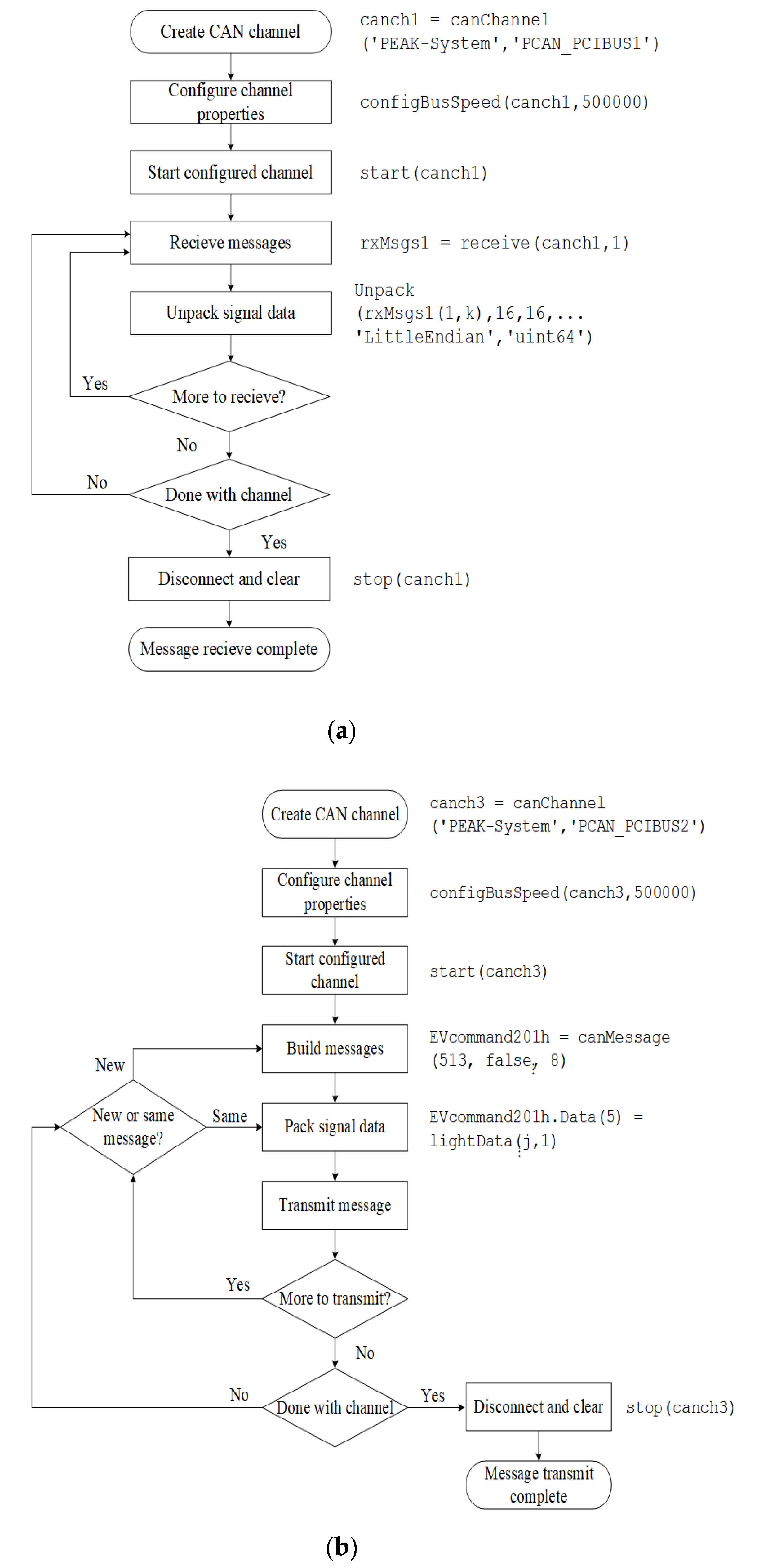
The Vehicle Network Communication Toolbox provided by MATLAB is used as monitoring, sending, receiving, encoding, and decoding CAN, CAN FD, J1939, and XCP messages. The CAN bus transmit and receive workflows are shown in
Figure 3a,b, respectively.
In both of the transmitting and receiving workflows, we set up the CAN bus channel first and then decide the channel bus speed. Next, each CAN message has its own identity, and the length of the CAN data has to be set up to pack/unpack the signal data. The transmitting and receiving processes stop when the message transmit/receive is complete.
- (1)
VCU Communication Protocol
For the vehicle control unit (VCU) communication interface, the brake, turn signal, transmission, throttle, and steering wheel control are commanded/sensed by transmitting/receiving CAN bus signals.
Table 1 and
Table 2 represent the lists of CAN bus protocol of the system.
- (2)
Throttle Control Based on Curtis Motor Controller
For throttle control of the electric golf car, the level of the throttle is determined by variable command between 0 to 5 voltage from the Curtis motor controller. The Curtis motor controller is then integrated with VCU. The throttle command of 5 volt corresponds to the vehicle velocity of 20 km/hr.
- (3)
Brake Control by Electric Cylinder
For brake control, the level (0–10 mm) of the brake is determined by a variable command between 0 to 100% from the electric cylinder.
- (4)
Steer-by-Wire Control by Electric Motor
For steering control, the steering angle of the steering wheel is determined by variable command between −450° to +450° from the electric power steering motor. Notice that the range from −450° to 450° degrees is the rotation angle of the steering wheel, where the zero-degree is the initial position and ±450° degree is at full lock. The degree defines a positive value when the steering wheel is rotating clockwise; otherwise, it is a negative value.
- (5)
Vehicle Speed Acquisition by Rotary Speed Sensor
The vehicle network communication toolbox in MATLAB is utilized to monitor and analyze the CAN bus messages. Simultaneously, a decision-making algorithm is developed, and the commands for the turn signal, throttle, steering and braking are issued to the VCU.
3. Autonomous Overtaking System Design
Figure 2 shows that the vision-based environment perception module is first used to derive the information of the lane lines and approaching vehicles. A windshield-mounted camera is employed to capture the front view of the scene and to detect the lane lines and approaching vehicles. To consider real-time lane line recognition and implementation of the automotive embedded system, a canny edge filter, and the Hough transform scheme are used to identify the lane lines [
34,
35,
36]. Moreover, by combing through the feature-based and appearance-related features approaches, containing shapes, symmetry, textures, and dimensions, and SVM classifier, the vehicle in front of the host vehicle can be detected [
34,
37,
38]. In addition, information on the vehicle attitude and status are derived using a gyro sensor and VCU. Based on the perception results, the lane line position, vanishing point, ego velocity
, distance between tires and lines
and
, and relative yaw angle
are derived using TLC computation materials and are subsequently employed as the basis for determining whether to remain in the lane or to change lanes. Moreover, the distance between the ego and approaching vehicles
; the length and width of the approaching vehicle, i.e.,
and
respectively; and the location of the approaching vehicle
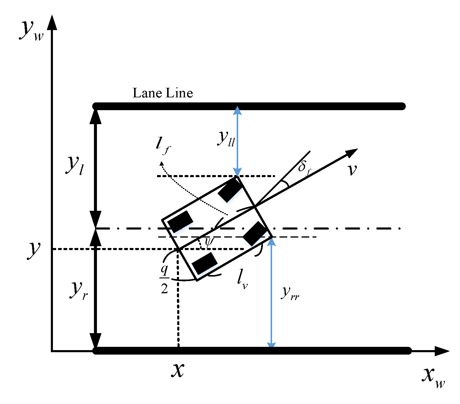
are used in the overtaking function. TLC is defined as the time available for the driver to make any lane changes. First, to examine as well as analyze the performance of the proposed method, a simple kinematics vehicle model and the geometric relationship of vehicle front tire and lane boundary are presented, as shown in
Figure 4.
The nonlinear kinematic vehicle model is described as follows:
where
and
y denote the longitudinal and lateral coordinates of the rear axle of the vehicle, respectively;
denotes the relative yaw angle of the vehicle;
denotes the length of the vehicle;
denotes the velocity of the vehicle;
is the acceleration of the center of mass in the same direction as the velocity; and
is the steering angle. The control inputs are the front and rear steering angles
and
. In addition,
and
are the distances between the front left and right tires to the left and right boundaries of the lane lines, respectively. Hence,
and
are defined as
where
and
are the lateral distances from the vehicle’s center of gravity (CG) to the left and right boundaries of the lanes, respectively. One can estimate the distance to lane crossing (DLC) using Equation (2), and then, the time to lane crossing (TLC) can be derived to correct the steering so that the vehicle stays entirely within a marked lane. Overtaking control is executed using the kinematic vehicle model and the model predictive control strategy to estimate the suitable steering angle and acceleration commands for the host vehicle that calls the autonomous overtaking function.
- (1)
Lane-Following Function
According to the lane detection results, the TLC can be utilized to predict when a vehicle departs from the current lane, refers to it as the condition for lane-following control, and then automatically adjusts the steering to maintain proper travel inside the lane without additional input from the driver. Thus, the unnecessary steering commands can be reduced in order to significantly improve the directional stability of vehicle. We should note that the steering angle is only determined by the relative yaw angle because the relative yaw angle may also be the same as that when the vehicle is not parallel to the lane. When the risk of lane departure is high, our proposed lane-following function immediately adjusts the steering wheel to ensure that the vehicle remains in the lane. When the risk of lane departure is low even when the relative direction of the vehicle head is not parallel to the lane, our lane-following function stops adjusting the steering wheel. On the other hand, to reduce the discomfort of passengers from frequent adjustment of the steering wheel, TLC is used as an active condition of the steering wheel adjustment. TLC is calculated by dividing DLC by the vehicle speed [
31,
32,
33]. In this study, we only focus on the straight road scenarios when considering the zero steering angle and constant nonzero steering angle, respectively.
In the first case, the zero steering angle is considered; in addition, the vehicle posture is not parallel the lane lines, as shown in
Figure 5a.
In
Figure 5a, the vehicle crosses the lane boundary on the left side of the lane. The DLC [
31] is presented as follows:
This formula is valid when the relative yaw angle is positive. If the relative yaw angle is negative, it has to replace
with
. Hence, the TLC is obtained using
Case 2 is considered when the vehicle has the constant nonzero steering angle and the vehicle posture is not parallel to the lane lines, as shown in
Figure 5b. According to Ackerman’s condition for a front wheel steering system [
39,
40], the inner and outer wheels are defined based on the turning center
. Since steering is performed with the intention to maneuver the vehicle, i.e., the autonomous overtaking strategy aims for a certain trajectory curvature for a given steering angle. Hence, the steering angles of both the inner and outer wheels are reasonably assumed to be equal, aiming for a certain trajectory curvature. In this paper, we choose the steering angle
as the average of the left and right steering angle. Therefore, the radius of the path formula is
The radius of the circle arc path can be computed from the following process. First, three side lengths of a triangle
are obtained to calculate the radian. Computing
, we can then obtain
. Using the Pythagorean theorem to define the lengths of
a and
b in
Figure 5b,
and
. Hence, the distance
can be determined as
where
. The angle
in (5) using trigonometric identities is given by
. The vehicle crosses the lane boundary on the left side of the lane, and TLC [
32] can thus be described as
The steering angle is determined by the relative yaw angle, while TLC predicts the timing for overtaking. Based on TLC, the steering wheel can immediately be adjusted to ensure that the vehicle follows the lane when the risk of lane departure is high. Therefore, the lane-following function enhances the driving safety as well as decreases discomfort for the passengers.
- (2)
Overtaking Function
For the overtaking function, the environment sensing information, including the distance between the ego and the approaching vehicles , and the location , the width , and the length of the approaching vehicle, is first obtained. If an approaching vehicle is detected, distance between the ego and the approaching vehicles can be obtained and checked if the clearance in the left lane is satisfied. Otherwise, the ego vehicle implements the lane-following maneuver. According the abovementioned results of perception, a successive linearization-based MPC is then employed to predict the optimal steering angle, throttle, and brake commands for autonomous overtaking maneuver.
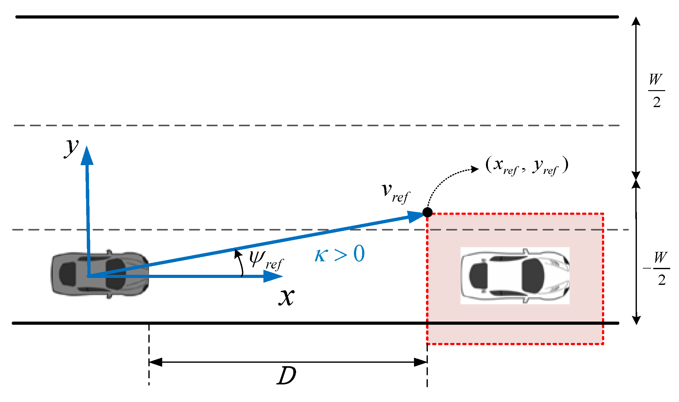
To define the area of the collision-free path, the constraints for the overtaking scenario are investigated in which an automated vehicle, which is referred to as the ego vehicle, approaches a slower moving leading vehicle, as shown in
Figure 6.
Figure 6 shows the constraints that are computed at each
for a left overtaking scenario, where the location constraints of the ego vehicle at each time step are indicated.
where
is the number of the prediction steps,
denotes the width of the road, and
is the slop of the overtaking constrained area.
is the lateral location of the approaching vehicle-collision avoidance area.
is set as half of the width of the approaching vehicle.
is the longitudinal location of the approaching vehicle-collision avoidance area.
is set as half of the length of the approaching vehicle. An image recognition scheme based on a camera is used to detect the approaching vehicle and the distance
between the ego and the approaching vehicle. If the ego vehicle has not overtaken the approaching vehicle,
is set as
. If the ego vehicle has overtaken the approaching vehicle,
is set as
. Moreover, according to the distance
and ego velocity, the TTC can be estimated as a condition for a safe overtaking action, and TTC can be described as
and must be greater than
. The parameter
sets 0.66 s as the driver reaction time when the driver sees danger and then performs a braking action [
41]. The details of the overtaking control algorithm are depicted as Algorithm 1.
| Algorithm 1: The Proposed Overtaking Control Algorithm |
Input:, and
1: while and constraints Equations (8)–(10) do
2: Solve the MPC problem by subject to Equation (12)
3: Obtain , and then
4: end while |
To implement the subsequent MPC design procedure, the linearization process is performed to convert the nonlinear kinematic vehicle model into an equivalent linear system. Hence, the state-space form of the vehicle system dynamics Equation (1) can be expressed as
where
and
, and
are the linearized matrices at current time
.
Remark 1. To ensure the safety, comfort, as well as mechanism hardware limitations of the proposed golf car, a rate of steering angle is limited 0.12 rad/s, i.e., approximately 6.8 degrees/sec. In addition, it is assumed that the vehicle drives at a constant speed of 7.2 km/h on a flat surface. Therefore, the nonlinear bicycle model can be linearized based on the initial points using the small angle approximation.
According to Equation (11), the predicted output can be formed as follows:
where
,
,
,
,
, and
for
.
In addition, the cost function in quadratic form at the sampling time step
is defined as follows:
where
specifies the generalized reference vector. To minimize the cost function, the optimal control law is derived by first element of vector
. Using the first-order necessary condition for optimality, we conclude that
. Therefore, the optimal control law
is
Note that the matrix is positive definite because and is also symmetric and at least positive semi-definite. In addition, applying a well-known second-order sufficiency condition of , we obtain , which implies that is a strict minimizer of .
Remark 2. The reference state vectoris based on the constraints for the overtaking scenario. As shown in Figure 6, the reference state, such as the locationsof the reference trajectory, the relative yaw angle, and the component of velocity, are obtained according the vision-based approaching vehicle detection and the constraints from the approaching vehicle collision avoidance area. 4. Experimental Results
To verify the performance of the proposed control scheme for autonomous overtaking system, two functions, involving a lane-following function when a relative yaw angle exists and an overtaking function when the approaching vehicle has a different lateral velocity, are considered. First, we develop a lane-following algorithm in the autonomous system. The designed lane-following algorithm based on TLC is compared with other lane following strategies such as the steering-activation strategy, which only depends on the lateral offset or relative yaw angle. Second, we adopt the successive linearization-based MPC to predict the optimal control laws for an overtaking scenario. Finally, we implement the system in an electric golf car. We utilize a PC with a camera, CAN-dual-channel-ISO, and the MATLAB Vehicle Network Communication Toolbox to receive all information of the vehicle and its velocity and apply this information into our algorithm. Then, the PC transmits the steering wheel, throttle, and brake commands with a CAN bus signal to the VCU to implement the autonomous overtaking system. The experimental results provide credible evidence that proves the favorable contributions of the proposed approach.
- (1)
Lane-Following Function Implementation
The experimental environment is a 3.7 m wide and 80 m long single lane with a T-junction. The vehicle velocity is restricted to 7.2 km/h. The lane line detection results are shown in
Figure 7. Thus, the vanishing point and the distance between the tires and lines can be derived. However, the system is incapable of understanding the potential risk of crossing the lane boundary. Thus, consider TLC as a risk indicator to demonstrate which method is better. We use it to predict the time when the vehicle departs from the current lane. The potential risk of lane departure is low when TLC is a large number. The ideal TLC is infinite. The main goal of this lane-following function is ascertaining that the vehicle follows the lane and satisfies the requirements of comfort and safety. In this study, we compare the lane-following function based on different conditions using traditional strategy (relative yaw angle and vehicle posture) and our proposed strategy (TLC).
In this first case, the lane-following decision is mainly based on the relative yaw angle between the centerline of the lane and the ego vehicle. Nevertheless, the vehicle is not perfectly parallel to the lane lines. A relative heading direction, which is the so-called relative yaw angle, exists in every moment. Hence, in Case 1, the relative yaw angle is treated as the condition for steering wheel adjustment. The adjustment extension of the steering wheel corresponds to the extension of the relative yaw angle.
Figure 8 shows the results of the lane-following control strategy based on the relative yaw angle.
Figure 8a shows the distance between the left tire and the line.
Figure 8b shows the distance between the right tire and the line.
Figure 8c,d show the relative yaw angle and steering wheel status, respectively.
Figure 8e,f show the TLC and vehicle velocity, respectively.
Although Case 1 successfully implemented the lane following control,
Figure 8c,d clearly show that the steering wheel angle is frequently adjusted mainly because the vehicle constantly corrects its yaw angle, thereby reducing the riding comfort, especially in a high-speed scenario, because of the existence of the relative yaw angle at every moment. In addition,
Figure 8e shows that TLC experiences drastic changes and has smaller values, which indicates that the risk of passing or crossing the lane is also higher.
To improve comfort, reducing the frequency of steering wheel adjustment is necessary. In Case 2, the lane following control strategy is designed based on DLC, which means that the steering angle and a certain distance in the lane boundary are both considered. The concept is that, although the car is not perfectly parallel with the lane lines, the tires still maintain sufficient distance from the lane boundary to refrain from crossing the lane; thus, adjusting the steering wheel is unnecessary.
Figure 9 shows the results of the lane following control strategy based on DLC.
Figure 9a shows the distance between the left tire and the line, and
Figure 9b shows the distance between the right tire and the line.
Figure 9c shows the relative yaw angle,
Figure 9d shows the steering wheel status,
Figure 9e shows the TLC, and
Figure 9f shows the vehicle velocity.
From the comparison of
Figure 8d and
Figure 9d, we can observe that the frequency of steering wheel adjustment in Case 2 is less than that in Case 1, which improves vehicle stability and riding comfort. Moreover, although this control strategy has successfully implemented the lane-following function and effectively reduced the frequency of steering wheel adjustment,
Figure 9e shows, however, that a potential risk of crossing the lane boundary still exists and becomes even more sensitive.
To reduce the potential risk and to increase comfort, we use TLC as the condition for adjustment according to the relative yaw angle and distance between the tires and lines.
Figure 10 shows the results of the lane-following control strategy based on TLC.
Figure 10a shows the distance between the left tire and the line, and
Figure 10b shows the distance between the right tire and the line.
Figure 10c,d show the relative yaw angle and steering wheel status, respectively.
Figure 10e shows the TLC, and
Figure 10f shows the vehicle velocity.
The experimental results indicate that the proposed lane-following control strategy that uses TLC demonstrates good performance compared with the previously mentioned strategies.
Figure 10c,d show that the steering wheel becomes smoother and has a smaller range of changes. More importantly, the number of adjustments is greatly reduced, effectively increasing the riding comfort and handling stability during the self-driving operation. A comparison of the abovementioned two cases demonstrates that the changing frequency of TLC is lower and that larger TLC value exists, which is intended to obtain the lowest risk in crossing the line. This strategy can not only enhance the riding comfort and vehicle stability but also make ensure that the autonomous system safely operates.
- (2)
Overtaking Function Implementation
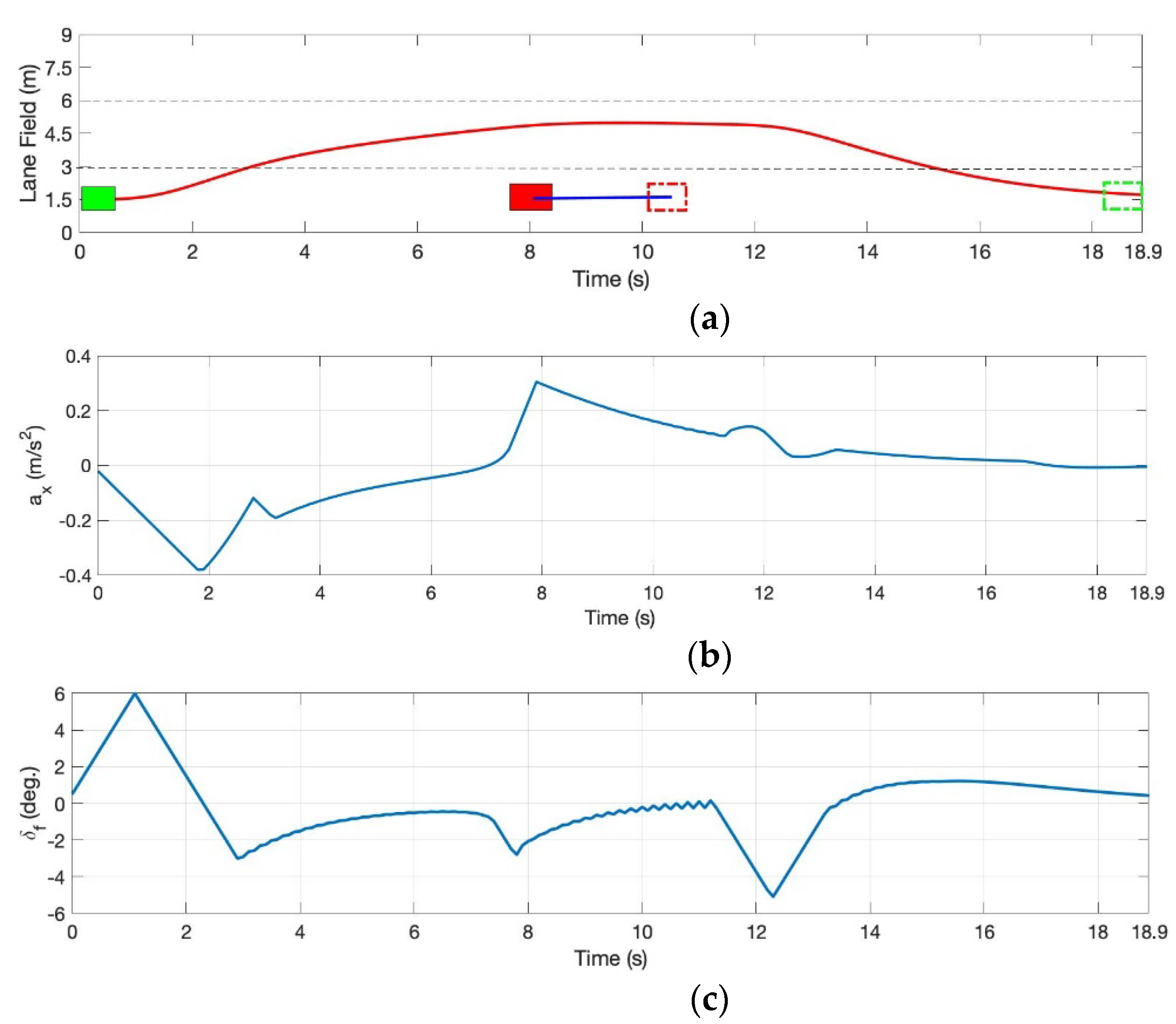
The experimental environment is a 2.2 m wide and 80 m long dual lane road. To perform an overtaking action within 50 m, we need to set the virtual approaching vehicle velocity as 0.1 m/s (0.36 km/h.). In this study, we perform two overtaking scenarios using the electric golf car. In the first scenario, the longitudinal velocity of the approaching vehicle is 0.36 km/h without lateral velocity. In the second scenario, the longitudinal and lateral velocities of the approaching vehicle are both 0.36 km/h. The experimental results of whole scenarios in overtaking function can be visualized via videos, which can be found at the following link
https://youtu.be/37q35gwl6fk (accessed on 28 July 2021). Considering that safety is the first priority, we restrict the maximum velocity in our experiment to 7.2 km/h. In addition, to ensure stringent overtaking maneuver, the faster test scenarios are simulated using MATLAB.
In the first scenario, the approaching vehicle moves forward without a lateral velocity and the speed is set as 0.36 km/h. The experimental results of the overtaking trajectory of the ego vehicle and its status are shown in
Figure 11, which shows that the ego vehicle performs lane-following control before and after the overtaking maneuver. In
Figure 11a, the red and green dotted boxes are the locations at the end time of the approaching vehicle and ego vehicle, respectively.
Using the TLC estimation to guarantee the minimal safe distance and to choose the best timing to overtake another vehicle, the optimal control commands, i.e., acceleration and steering angle of vehicle, using MPC strategy can be obtained to implement a safe overtaking maneuver procedure for an autonomous vehicle. The acceleration and steering angle commands are illustrated in
Figure 11b,c. In the overtaking system, the control commands from the host controller are a desired vehicle acceleration and steering angle that need to be shifted to the desired throttle opening and steering wheel.
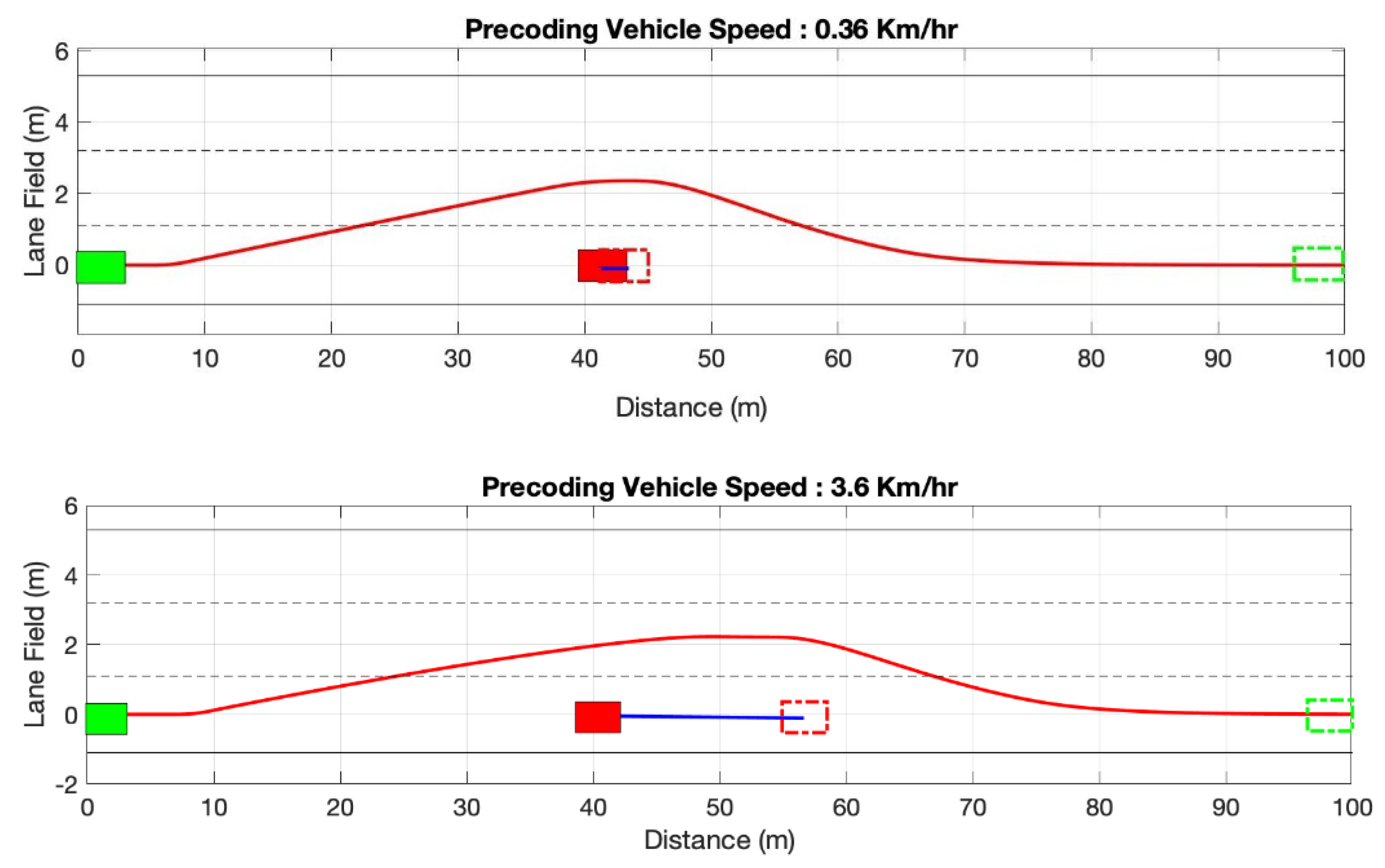
Next, we simulated the faster test scenarios using MATLAB, where the speed of the ego vehicle is increased to 18 km/h and where two different speeds of the approaching vehicle (0.36 and 3.6) are considered. The simulation results are presented as follows.
Figure 12 shows that the required overtaking distance is different at different speeds, and the longer the overtaking distance is, the faster the required speed.
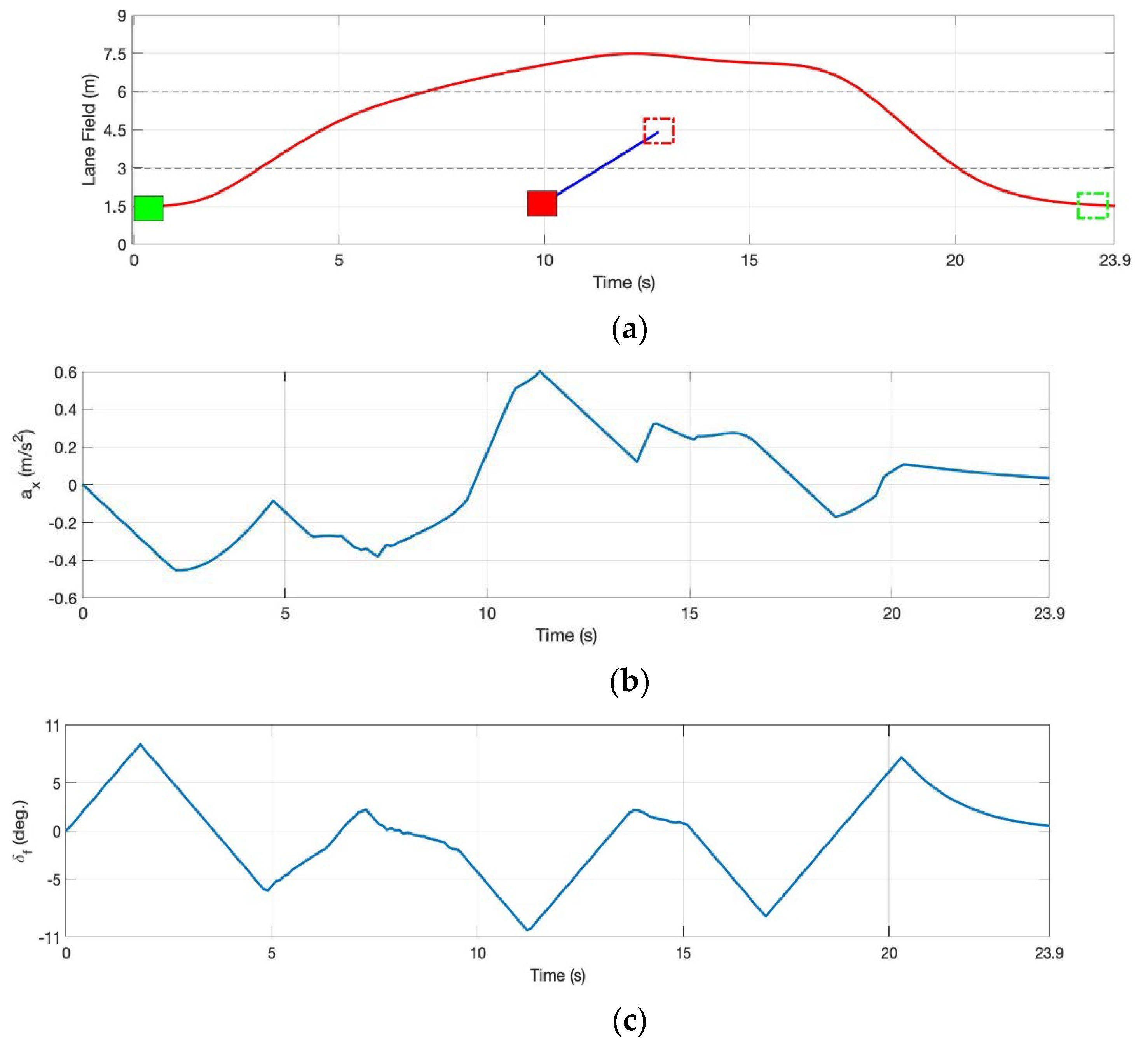
In this case, the approaching vehicle moves forward with a lateral velocity (0.36 km/h). The experimental results of the overtaking trajectory of the ego vehicle and its status are shown in
Figure 13.
In this case, we can obviously see that the steering angle of the vehicle is greater when the leading vehicle increases its lateral velocity.
Next, the faster test scenarios for two different lateral velocities of the approaching vehicle (0.36 and 3.6 km/h) are simulated in MATLAB. The speed of the ego vehicle is increased to 18 km/h. The simulation results are shown in
Figure 14.
Figure 14 shows that the required overtaking trajectory of the ego vehicle is also farther when the lateral velocity of the approaching vehicle is faster. In the abovementioned different lateral speeds, the proposed system can not only successfully complete the overtaking process but also demonstrates a fairly stable overtaking trajectory.
Remark 3. The limitations of this study are mainly due to mechanism hardware limitations of the proposed electric golf car: one is the maximum speed, and the other is tire steering angle. First, the maximum speed of our built electric golf car is limited to 7.2 km/h; therefore, only low-speed scenarios can be demonstrated. Second, it is limited by the steering mechanism of the golf car: the steering wheel controller has ±450° degrees of steering wheel rotations, which lock through a servo motor to turn its steering column, and correspondingly, the tire steering angle is only −28 to 18 degrees. Hence, a larger turning radius of the electric golf car is required, and the space needed when overtaking is larger.
