
Additional Information Delivery to Image Content via Improved Unseen–Visible Watermarking

 ,
,  , and
, and 
Abstract
:
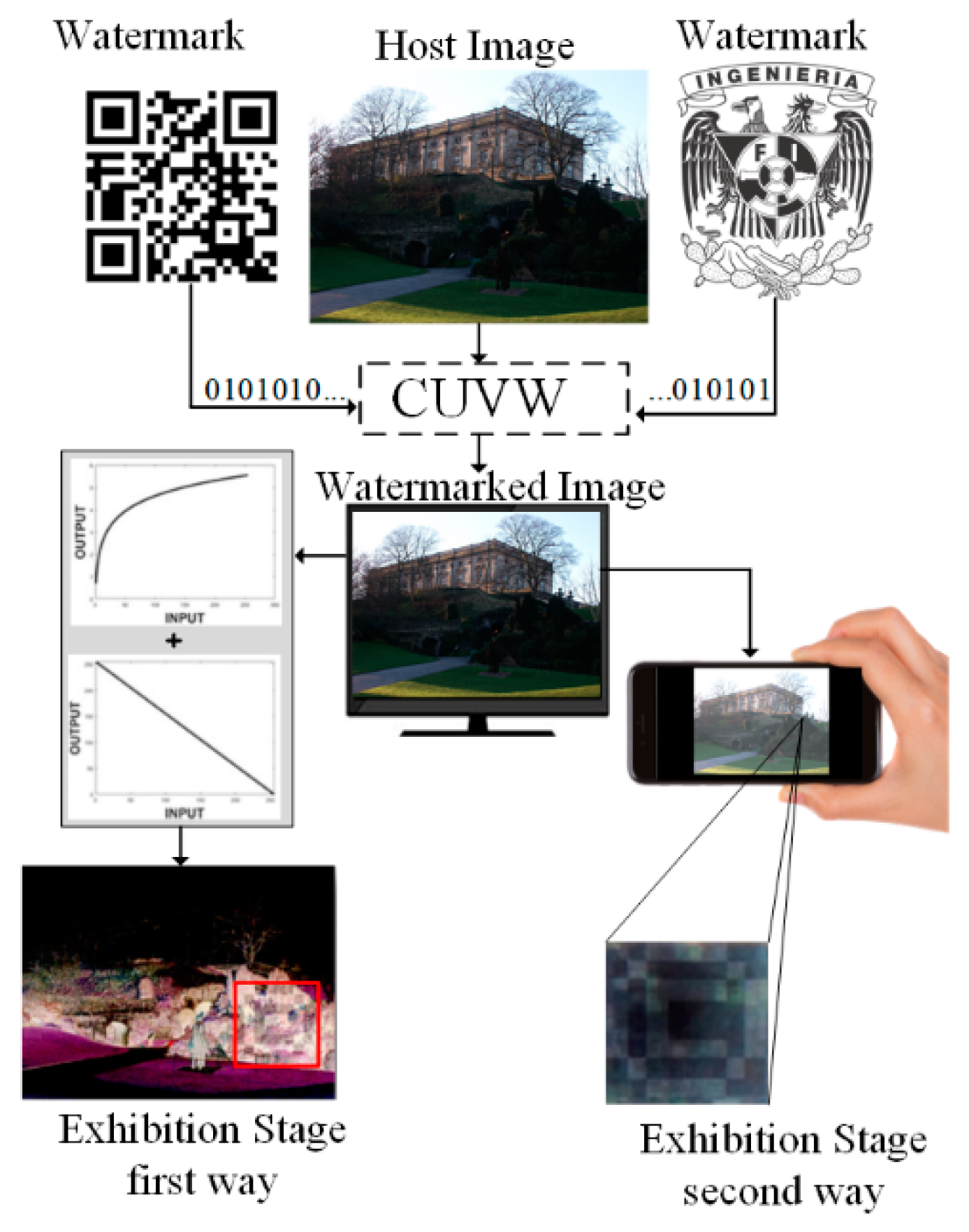
1. Introduction
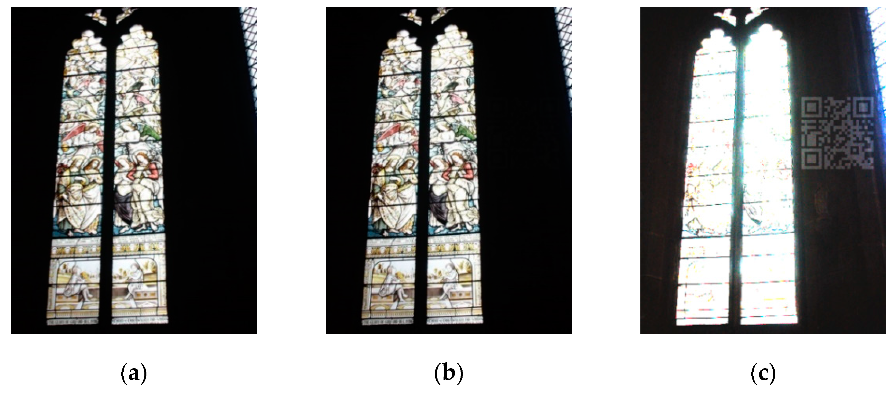
- First, the strategy to select the embedding region considers large smooth regions of low or high intensity, extending the applicability of the proposed algorithms to any class of images;
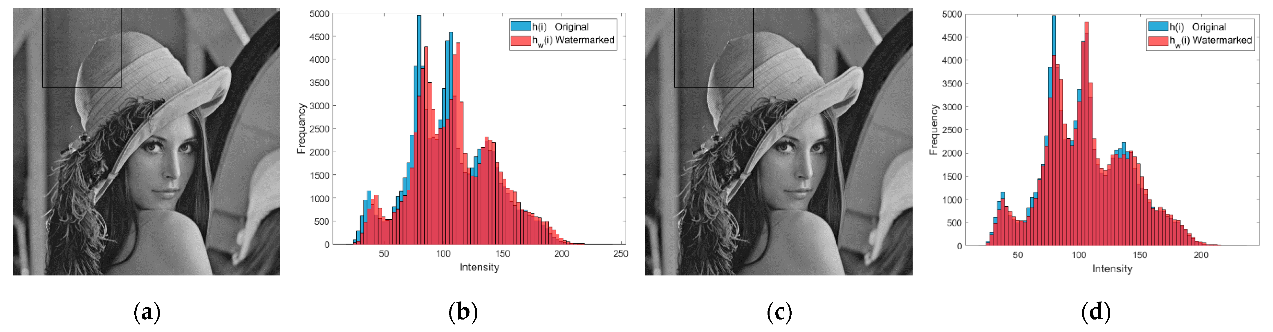
- Second, the watermark complement strategy is capable of reducing the histogram distortion and the visual degradation of the watermarked image;
- Third, a methodology to quantify the embedding error induced by the watermark embedding strategy is introduced.
2. Literature Survey
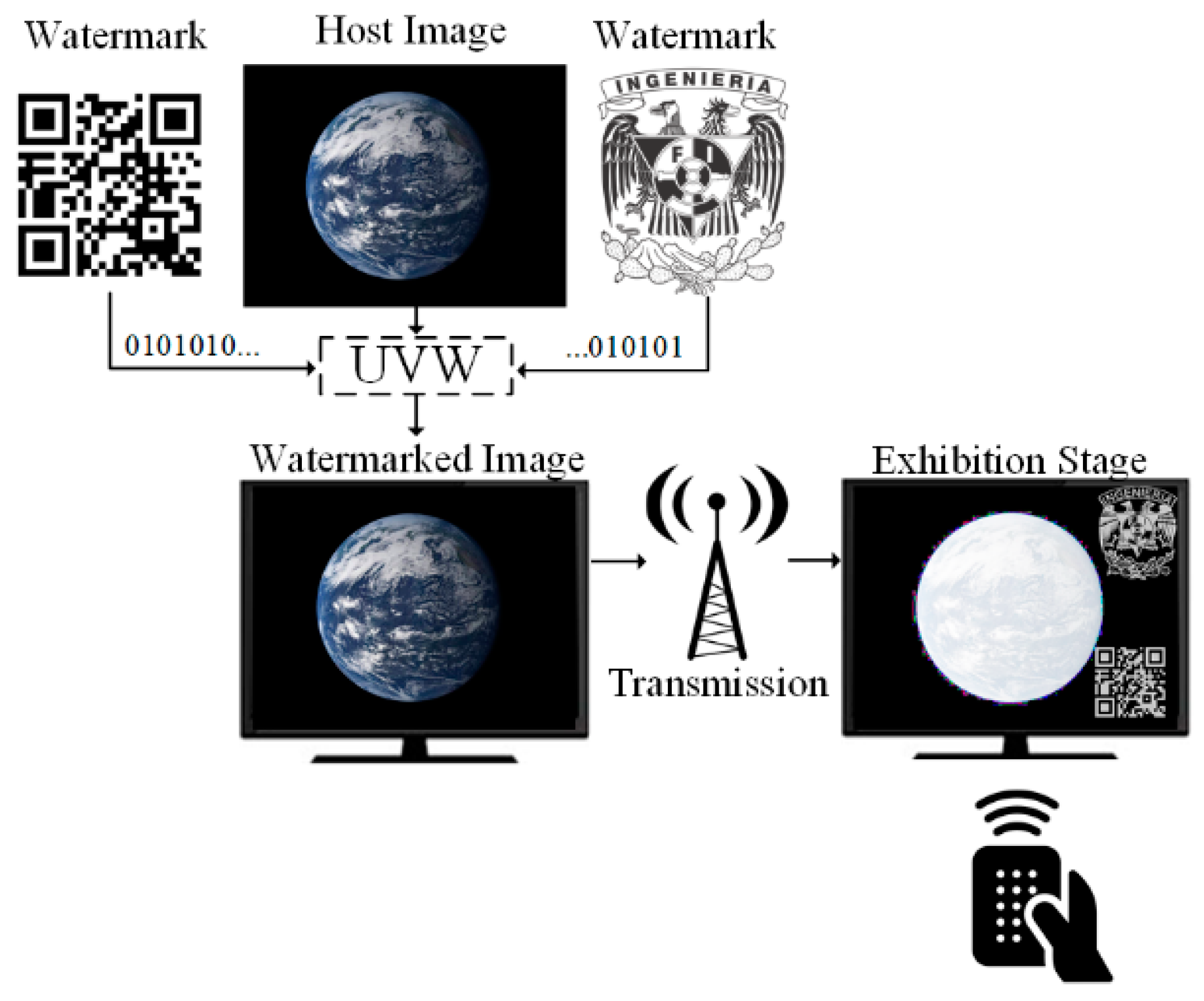
2.1. Unseen–Visible Watermarking
2.2. Improved Unseen–Visible Watermarking
2.3. Camouflaged Unseen–Visible Watermarking
2.4. Motivation
3. Materials and Methods
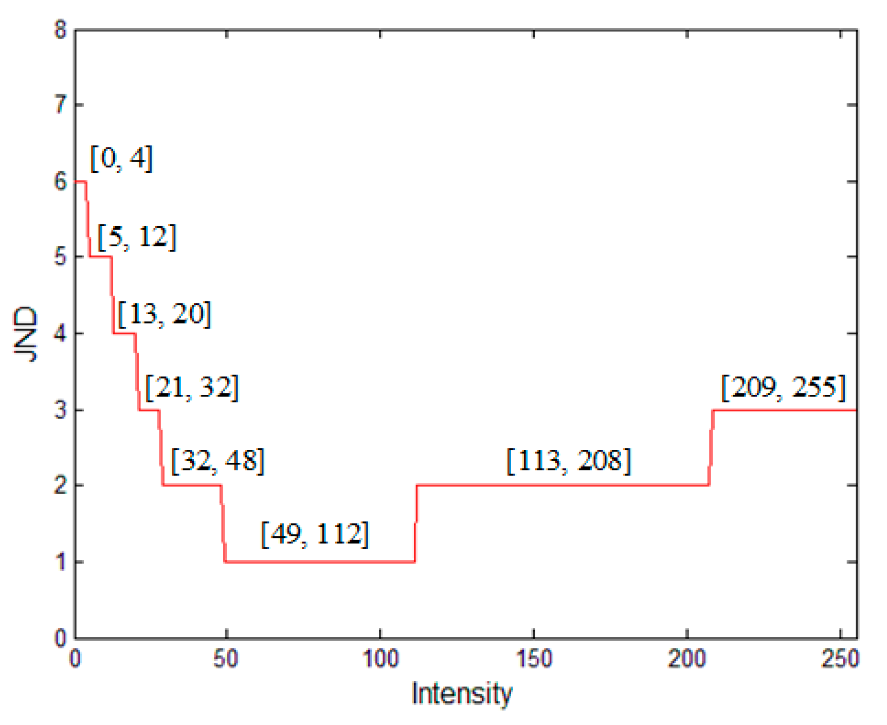
3.1. Just Noticeable Distortion (JND)
3.2. Watermark Complement Strategy (WCS)
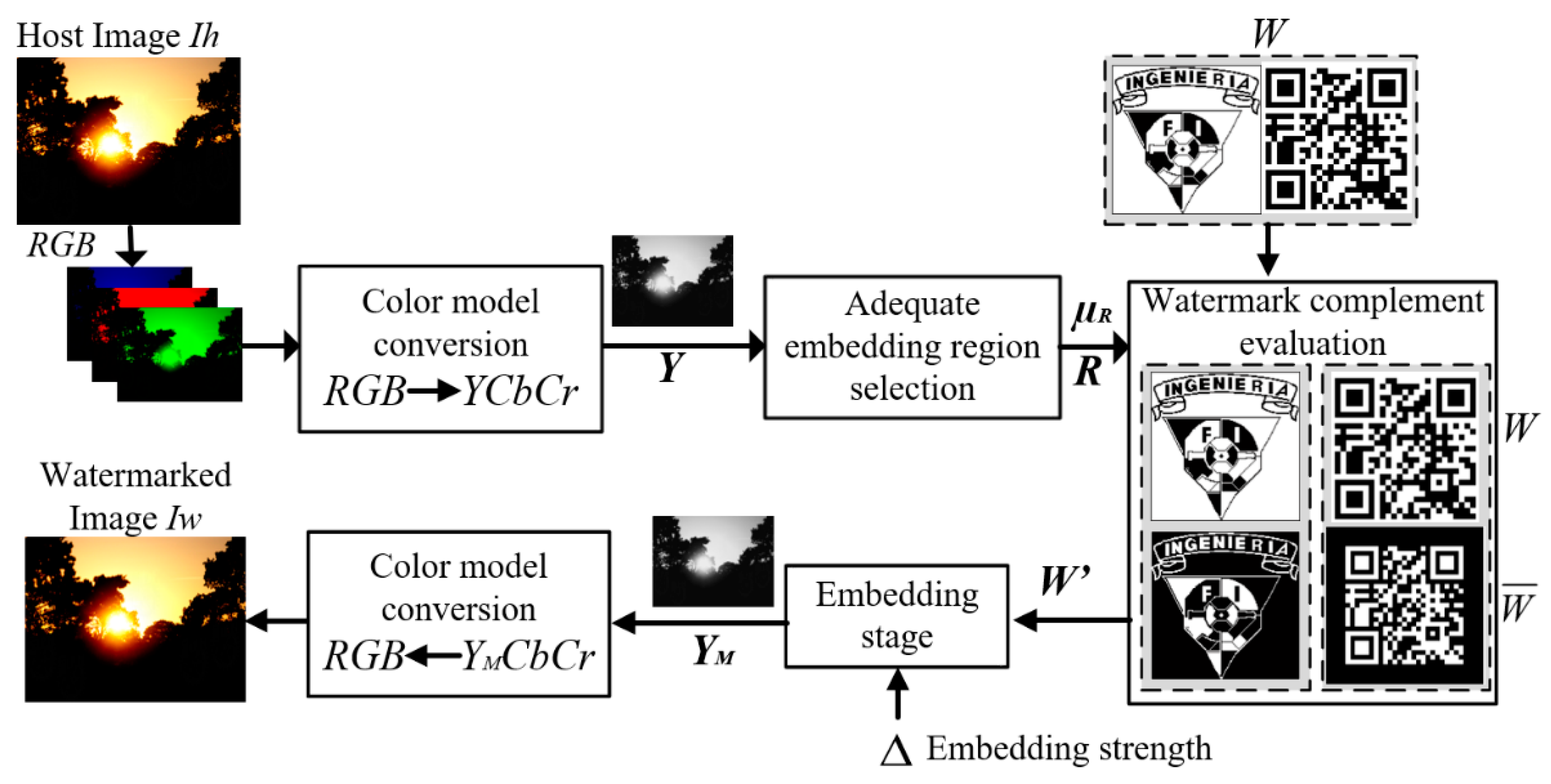
3.3. Proposed Watermarking Algorithm
3.3.1. Embedding Stage
- 1.
- The host image
- 2.
- Adequate embedding region
- 3.
- Embedding Strength
- 4.
- Embedding Strategy
| Algorithms 1. Embedding survey. |
| Input: Host Image Ih, watermark W. |
|
| Output: Watermarked image Iw. |
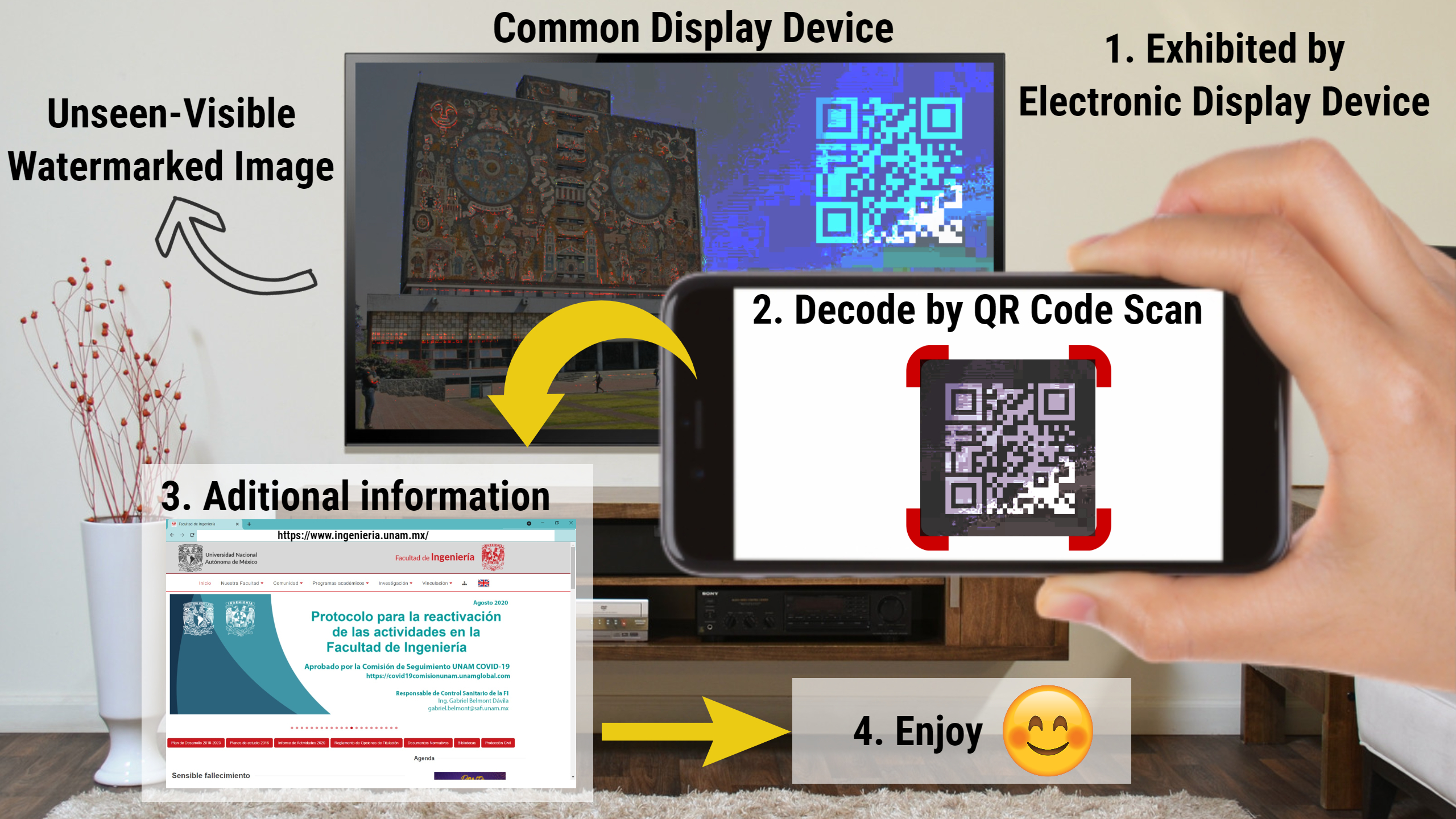
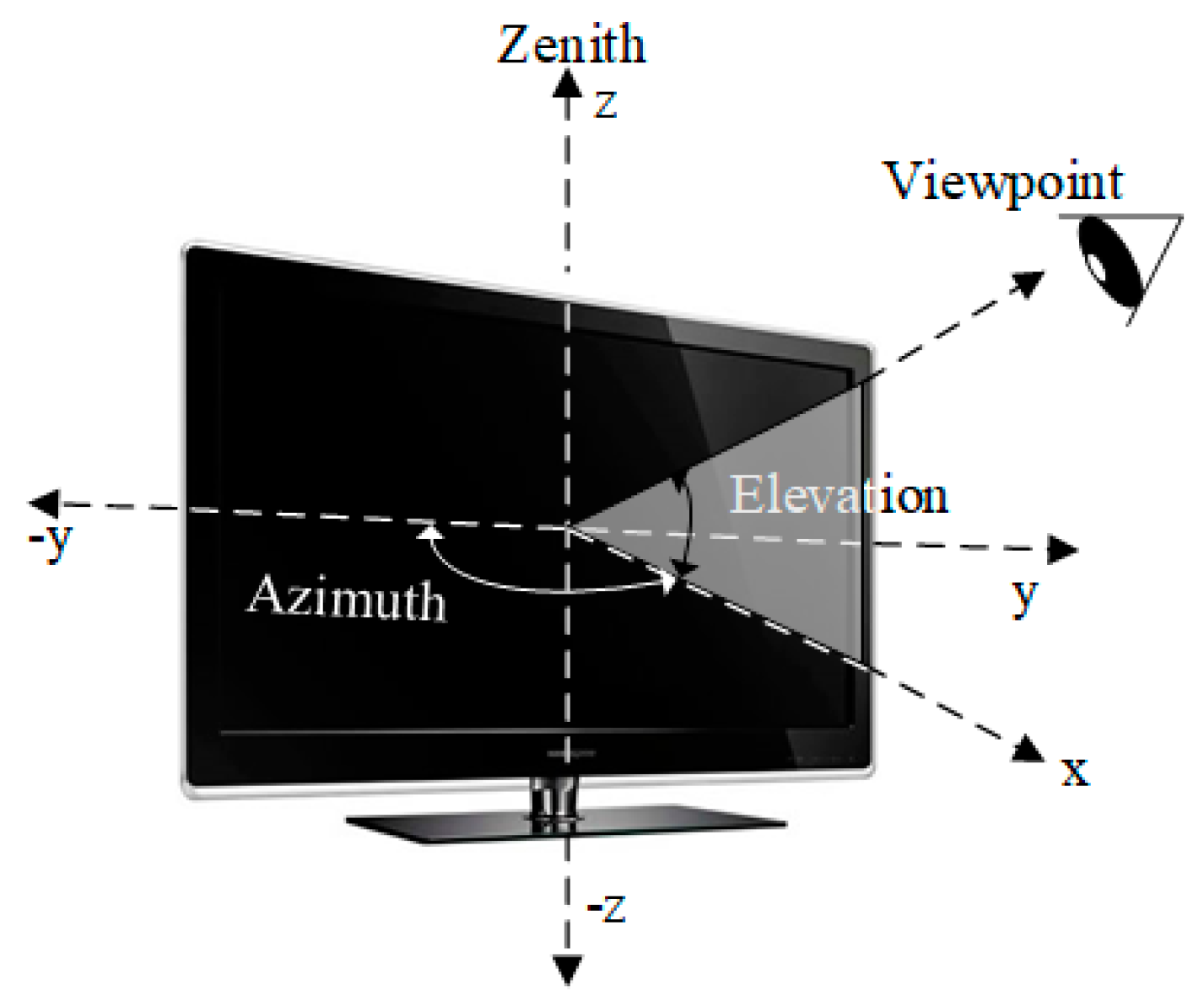
3.3.2. Exhibition Stage
- 1.
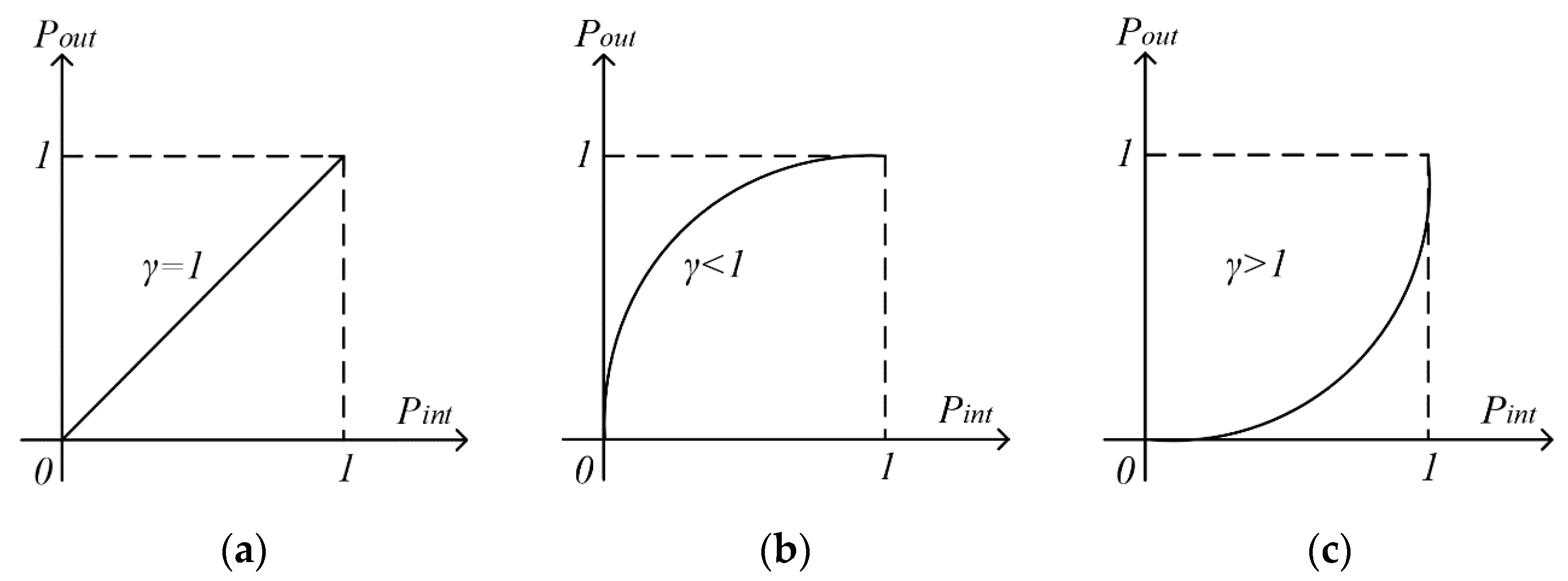
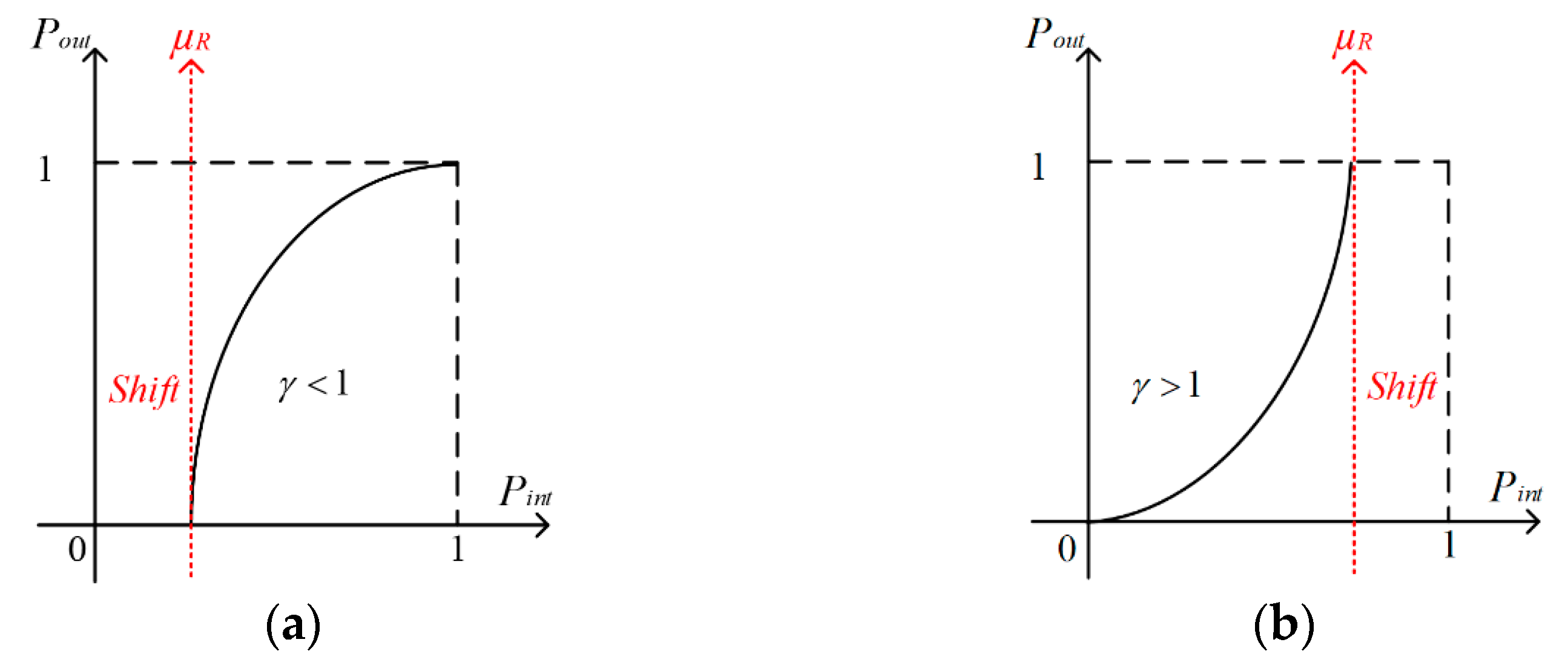
- Gamma Correction Function (GCF)
- 2.
- Other feasible exhibition strategies
4. Experimental Results and Analysis
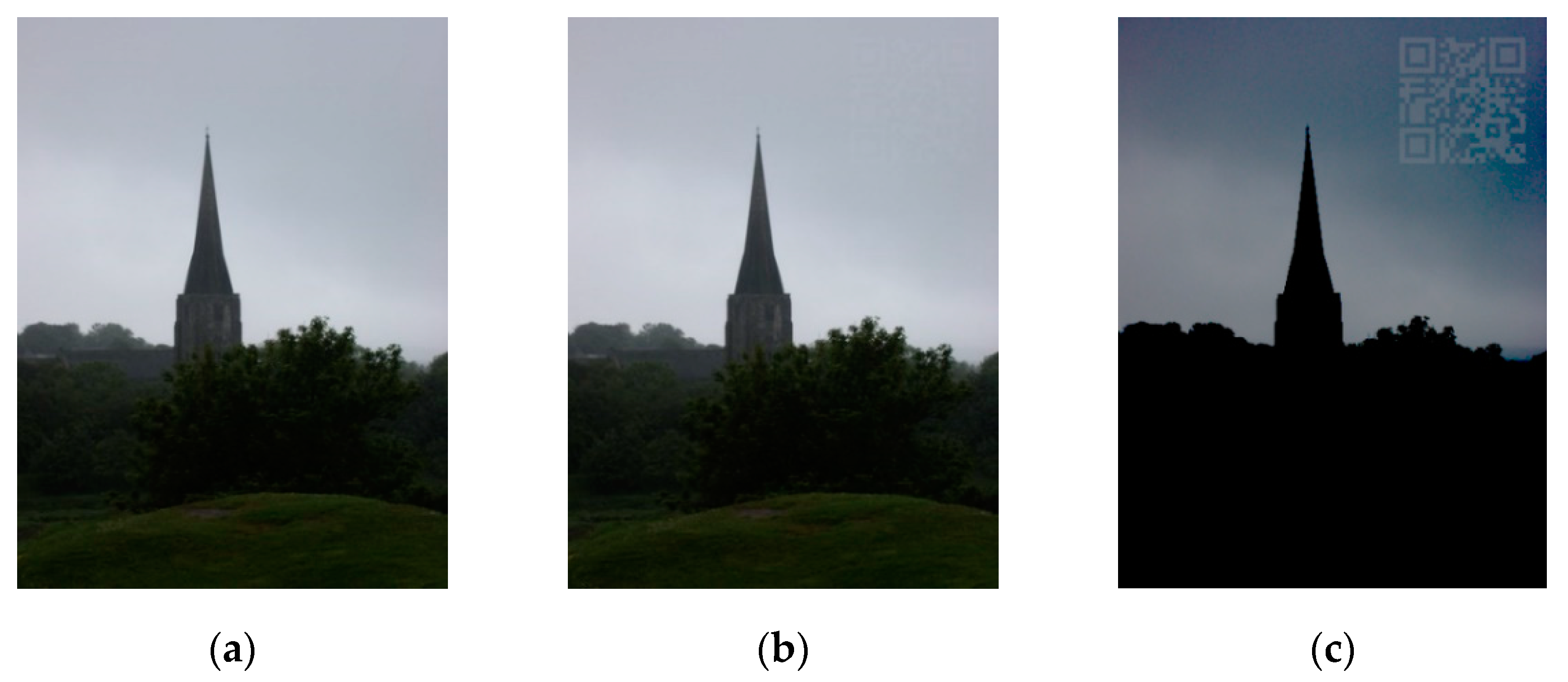
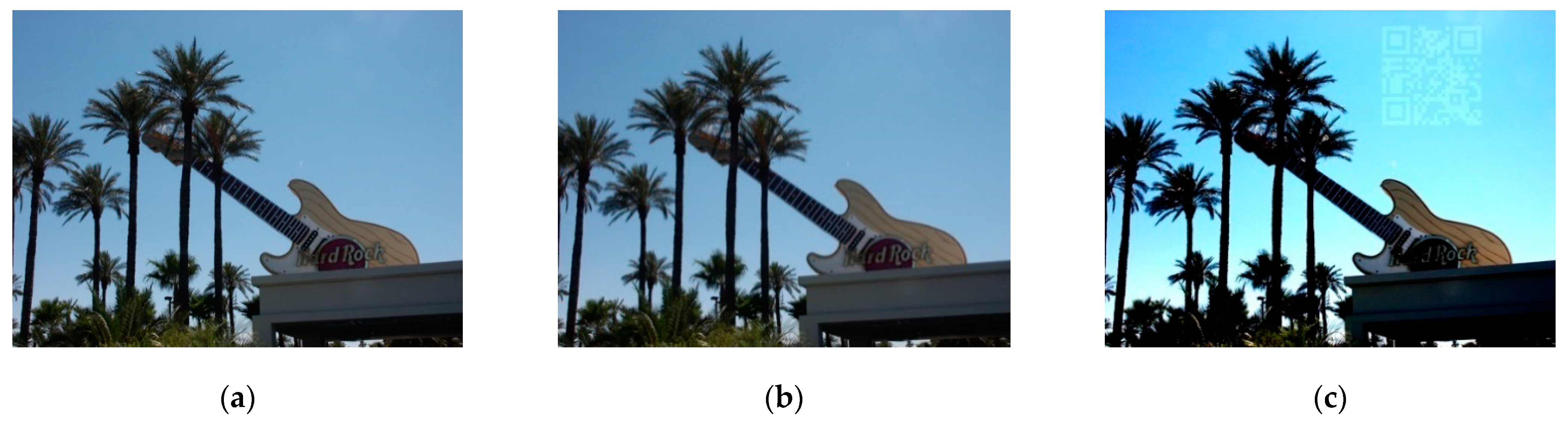
4.1. General Performance Validation
4.2. Watermark Robustness
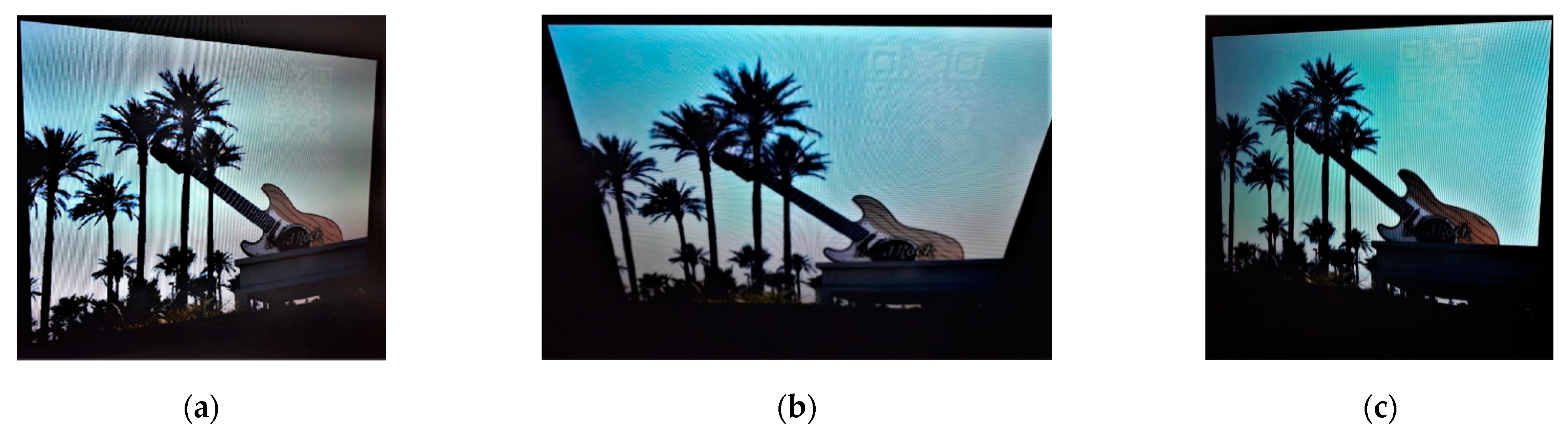
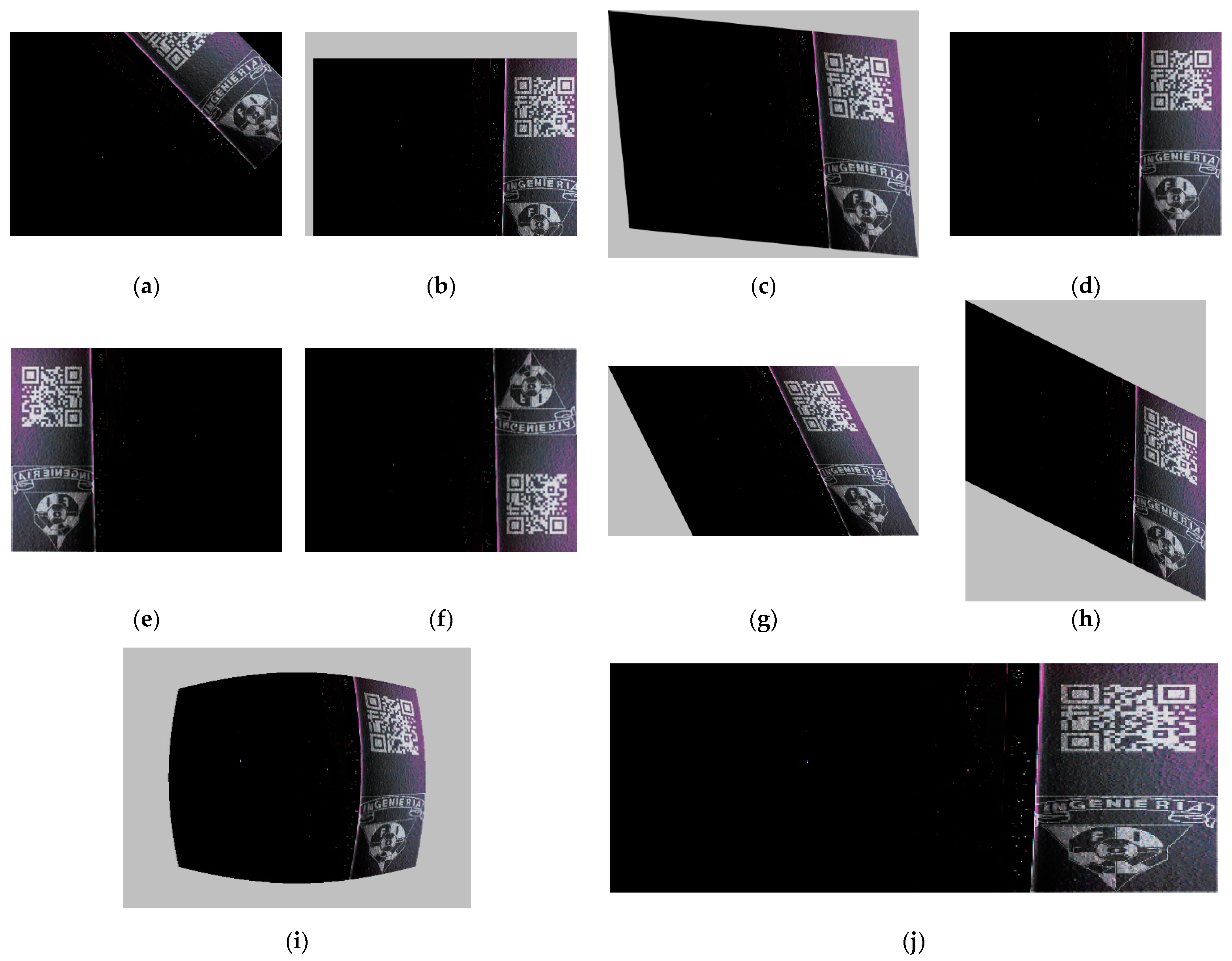
4.2.1. Robustness to Image Geometric Attacks
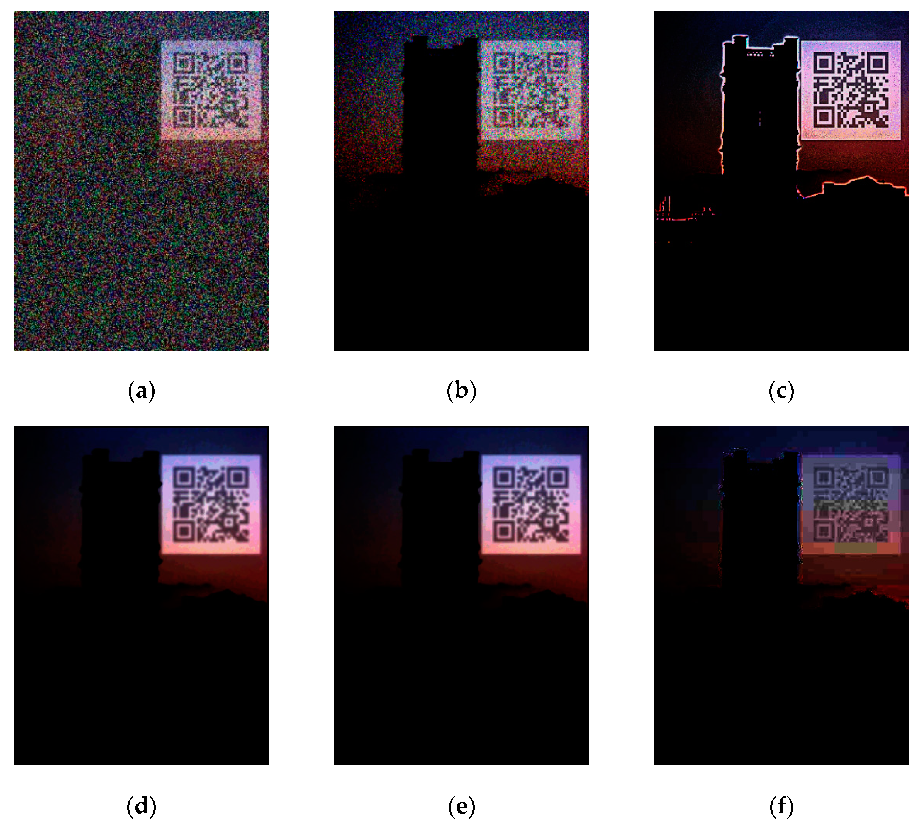
4.2.2. Robustness to Image Processing Attacks
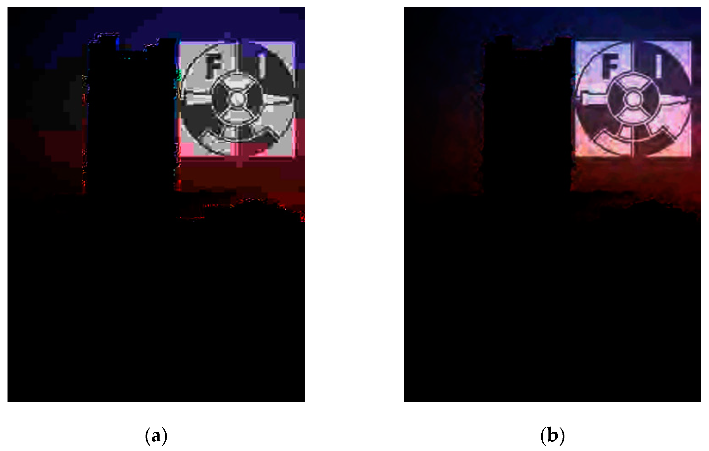
4.2.3. Performance Comparison and Discussion
5. Conclusions
Author Contributions
Funding
Acknowledgments
Conflicts of Interest
References
- Cox, I.J.; Kilian, J.; Leighton, F.T.; Shamoon, T. Secure spread spectrum watermarking for multimedia. IEEE Trans. Image Process. 1997, 6, 1673–1687. [Google Scholar] [CrossRef]
- Barni, M.; Bartolini, F. Watermarking Systems Engineering, 1st ed.; Marcel Dekker: New York, NY, USA, 2004; pp. 23–43. [Google Scholar]
- Hu, Y.; Kwong, S.; Huang, J. An algorithm for removable visible watermarking. IEEE Trans. Circuits Syst. Video Technol. 2006, 16, 129–133. [Google Scholar] [CrossRef]
- Rosales-Roldan, L.; Cedillo-Hernandez, M.; Chao, J.; Nakano-Miyatake, M.; Perez-Meana, H. Watermarking-based Color Image Authentication with Detection and Recovery Capability. IEEE Lat. Am. Trans. 2016, 14, 1050–1057. [Google Scholar] [CrossRef]
- Muñoz-Ramirez, D.O.; Ponomaryov, V.; Reyes-Reyes, R.; Cruz-Ramos, C.; Sadovnychiy, S. Embedding a Color Watermark into DC coefficients of DCT from Digital Images. IEEE Lat. Am. Trans. 2019, 17, 1326–1334. [Google Scholar] [CrossRef]
- Huang, C.; Chuang, S.; Huang, Y.; Wu, J. Unseen Visible Watermarking: A Novel Methodology for Auxiliary Information Delivery via Visual Contents. IEEE Trans. Inf. Forensics Secur. 2009, 4, 193–206. [Google Scholar] [CrossRef]
- Juarez-Sandoval, O.; Fragoso-Navarro, E.; Cedillo-Hernandez, M.; Nakano, M.; Perez-Meana, H.; Cedillo-Hernandez, A. Improved unseen-visible watermarking for copyright protection of digital image. In Proceedings of the 5th International Workshop on Biometrics and Forensics (IWBF), Coventry, UK, 4–5 April 2017; pp. 1–5. [Google Scholar] [CrossRef]
- Juarez-Sandoval, O.; Cedillo-Hernandez, M.; Nakano, M.; Cedillo-Hernandez, A.; Perez-Meana, H. Digital image ownership authentication via camouflaged unseen-visible watermarking. Springer Multimed. Tools Appl. 2018, 77, 26601–26634. [Google Scholar] [CrossRef]
- Lin, P.Y. Imperceptible Visible Watermarking Based on Postcamera Histogram Operation. Elsevier J. Syst. Softw. 2014, 95, 194–208. [Google Scholar] [CrossRef]
- Juarez-Sandoval, O.; Fragoso-Navarro, E.; Cedillo-Hernandez, M.; Cedillo-Hernandez, A.; Nakano, M.; Perez-Meana, H. Improved imperceptible visible watermarking algorithm for auxiliary information delivery. IET Biom. 2018, 7, 305–313. [Google Scholar] [CrossRef]
- Juarez-Sandoval, O.U.; Garcia-Ugalde, F.; Cedillo-Hernandez, M.; Ramirez-Hernandez, J. Imperceptible visible watermarking with watermark readability improved. In Proceedings of the IEEE International Autumn Meeting on Power, Electronics and Computing (ROPEC), Guerrero, Mexico, 4–6 November 2020; pp. 1–6. [Google Scholar] [CrossRef]
- Denso Wave Incorporated. Quick Response Code. Available online: https://www.qrcode.com/ (accessed on 22 January 2021).
- Gamma Correction Function. Available online: https://www.mathworks.com/help/images/ref/imadjust.html?s_tid=srchtitle (accessed on 1 July 2021).
- ANSI/INFOCOMM 3M-2011, Projected Image System Contrast Ratio. Available online: https://www.avixa.org/standards/projected-image-system-contrast-ratio (accessed on 15 December 2020).
- Mendoza-Mata, D.; Cedillo-Hernandez, M.; Garcia-Ugalde, F.; Cedillo-Hernandez, A.; Nakano-Miyatake, M.; Perez-Meana, H. Secured telemedicine of medical imaging based on dual robust watermarking. Int. J. Comput. Graph. Vis. Comput. 2021, 1432–2315. [Google Scholar] [CrossRef]
- Nuñez-Ramirez, D.; Cedillo-Hernandez, M.; Nakano-Miyatake, M.; Perez-Meana, H. Efficient Management of Ultrasound Images using Digital Watermarking. IEEE Lat. Am. Trans. 2020, 18, 1398–1406. [Google Scholar] [CrossRef]
- Park, S.-W.; Ko, J.-S.; Huh, J.-H.; Kim, J.-C. Review on Generative Adversarial Networks: Focusing on Computer Vision and Its Applications. Electronics 2021, 10, 1216. [Google Scholar] [CrossRef]
- Abdelhedi, K.; Chaabane, F.; Amar, C.-B. A SVM-based zero-watermarking technique for 3D videos traitor tracing. In Proceedings of the Springer 20th International Conference, Advance Concepts for Intelligence Vision Systems 2020, Auckland, New Zealand, 10–14 February 2020; pp. 373–383. [Google Scholar] [CrossRef]
- Lee, H.; Park, S.-H.; Yoo, J.-H.; Jung, S.-H.; Huh, J.-H. Face Recognition at a Distance for a Stand-Alone Access Control System. Sensors 2020, 20, 785. [Google Scholar] [CrossRef] [PubMed] [Green Version]
- Ray, A.; Roy, S. Recent trends in image watermarking techniques for copyright protection: A survey. Int. J. Multimed. Inf. Retr. 2020, 9, 249–270. [Google Scholar] [CrossRef]
- Wright, S.L.; Greier, P.F. Low-cost method to improve viewing angle characteristics of twisted-nematic mode liquid-crystal displays. SID Symposium Digest Tech. Papers 2002, 33, 717–719. [Google Scholar] [CrossRef]
- Wu, C.W.; Thompson, G.; Wright, S.L. Multiple images viewable on twisted-nematic mode liquid-crystal displays. IEEE Signal Process. Lett. 2003, 10, 225–227. [Google Scholar] [CrossRef]
- Yin, W.; Goldfarb, D.; Osher, S. Total Variation Based Image Cartoon-Texture Decomposition; CORC Report TR-2005-01, UCLA CAM Report 05-27; Columbia University: New York, NY, USA, 2005. [Google Scholar]
- Yang, X.K.; Lin, W.S.; Lu, Z.K.; Ong, E.P.; Yao, S.S. Just noticeable distortion model and its applications in video coding. Elsevier Signal Process. Image Commun. 2005, 20, 662–680. [Google Scholar] [CrossRef]
- Yu, P.; Shang, Y.; Li, C. A new visible watermarking technique applied to CMOS image sensor. In Proceedings of the SPEI SPIE 8917, MIPPR 2013: Multispectral Image Acquisition, Processing, and Analysis, Wuhan, China, 26–27 October 2013; pp. 891719-1–891719-7. [Google Scholar] [CrossRef]
- Jung, S.; Ha, L.T.; Ko, S. A New Histogram Modification Based Reversible Data Hiding Algorithm Considering the Human Visual System. IEEE Signal Process. Lett. 2011, 18, 95–98. [Google Scholar] [CrossRef]
- Liu, H.; Zhang, Y.; Zhang, H.; Fan, C.; Kwong, S.; Jay-Kuo, C.-C.; Fan, X. Deep Learning-Based Picture Wise Just Noticeable Distortion Prediction Model for Image Compression. IEEE Trans. Image Process. 2020, 29, 641–656. [Google Scholar] [CrossRef]
- Fragoso-Navarro, E.; Cedillo-Hernández, M.; Nakano-Miyatake, M.; Cedillo-Hernández, A.; Pérez-Meana, H. Visible Watermarking Assessment Metrics Based on Just Noticeable Distortion. IEEE Access 2018, 6, 75767–75788. [Google Scholar] [CrossRef]
- Huang, J.; Shi, Y.Q. Adaptive image watermarking scheme based on visual masking. IET Electron. Lett. 1998, 34, 748–750. [Google Scholar] [CrossRef] [Green Version]
- Perez-Daniel, K.R.; Garcia-Ugalde, F.; Sanchez, V. Watermarking of HDR Images in the Spatial Domain With HVS-Imperceptibility. IEEE Access 2020, 8, 156801–156817. [Google Scholar] [CrossRef]
- Ni, Z.; Shi, Y.Q.; Ansari, N.; Su, W. Reversible data hiding. IEEE Trans. Circuits Syst. Video Technol. 2006, 16, 354–362. [Google Scholar] [CrossRef]
- Chung, K.-L.; Huang, Y.-H.; Yan, W.-M.; Teng, W.-C. Distortion reduction for histogram modification-based reversible data hiding. Elsevier Appl. Math. Comput. 2012, 218, 5819–5826. [Google Scholar] [CrossRef]
- Singh, L.; Singh, A.K.; Singh, P.K. Secure data hiding techniques: A survey. Springer Multimed. Tools Appl. 2020, 79, 15901–15921. [Google Scholar] [CrossRef]
- Wan, W.; Zhou, K.; Zhang, K.; Zhan, Y.; Li, J. JND-Guided Perceptually Color Image Watermarking in Spatial Domain. IEEE Access 2020, 8, 164504–164520. [Google Scholar] [CrossRef]
- Zhang, F.; Luo, T.; Jiang, G.; Yu, M.; Xu, H.; Zhou, W. A novel robust color image watermarking method using RGB correlations. Springer Multimed. Tools Appl. 2019, 78, 20133–20155. [Google Scholar] [CrossRef]
- Li, B.; Zhang, Y. Design of digital watermark detection system based on handheld devices. In Proceedings of the IEEE International Conference on Computer Science and Electronics Engineering (ICCSEE), Hangzhou, China, 23–25 March 2012; pp. 52–55. [Google Scholar] [CrossRef]
- Wang, Z.; Bovik, A.C.; Sheikh, H.R.; Simoncelli, E.P. Image quality assessment: From error visibility to structural similarity. IEEE Trans. Image Process. 2004, 13, 600–612. [Google Scholar] [CrossRef] [Green Version]
- Chang, H.; Chen, H.H. Stochastic Color Interpolation for Digital Cameras. IEEE Trans. Circuits Syst. Video Technol. 2007, 17, 964–973. [Google Scholar] [CrossRef]
- Schaefer, G.; Stich, M. UCID: An uncompressed color image database. In Proceedings of the SPIE Storage and Retrieval Methods and Applications for Multimedia, San Jose, CA, USA, 18–22 January 2004; Volume 5307, pp. 472–480. [Google Scholar] [CrossRef]
- Park, Y.; Kim, J.; Kim, M.; Lee, W.; Lee, S. Programmable multimedia platform based on reconfigurable processor for 8K UHD TV. IEEE Trans. Consum. Electron. 2015, 61, 516–523. [Google Scholar] [CrossRef]
- Wang, H.; Zhang, X.; Wang, T.; Li, W.; Chen, Q.; Ren, P.; Wu, X.; Sun, H. A 4K × 2K@60fps Multifunctional Video Display Processor for High Perceptual Image Quality. IEEE Trans. Circuits Syst. I Regul. Pap. 2020, 67, 451–463. [Google Scholar] [CrossRef]
- Caviedes, J.E. The Evolution of Video Processing Technology and Its Main Drivers. Proc. IEEE 2012, 100, 872–877. [Google Scholar] [CrossRef]
- Xu, C.; Peng, Z.; Hu, X.; Zhang, W.; Chen, L.; An, F. FPGA-Based Low-Visibility Enhancement Accelerator for Video Sequence by Adaptive Histogram Equalization With Dynamic Clip-Threshold. IEEE Trans. Circuits Syst. I Regul. Pap. 2020, 67, 3954–3964. [Google Scholar] [CrossRef]
- Li, Z.; Wang, J.; Sylvester, D.; Blaauw, D.; Kim, H.S. A 1920 × 1080 25-Frames/s 2.4-TOPS/W Low-Power 6-D Vision Processor for Unified Optical Flow and Stereo Depth with Semi-Global Matching. IEEE J. Solid-State Circuits 2019, 54, 1048–1058. [Google Scholar] [CrossRef]
- Bucolo, M.; Buscarino, A.; Fortuna, L.; Famoso, C. Stochastic resonance in imperfect electromechanical Systems. In Proceedings of the IEEE 29th International Symposium on Industrial Electronics (ISIE), Delft, The Netherlands, 17–19 June 2020; pp. 210–214. [Google Scholar] [CrossRef]
- Bucolo, M.; Buscarino, A.; Famoso, C.; Fortuna, L.; Gagliano, S. Imperfections in Integrated Devices Allow the Emergence of Unexpected Strange Attractors in Electronic Circuits. IEEE Access 2021, 9, 29573–29583. [Google Scholar] [CrossRef]


| Attack | Specification |
|---|---|
| Rotation | Angle 45° |
| Translation with cropping | x = 15, y = 50 |
| Affine transformation | (1,0.1,0;0.1,1,0;0,0,1) |
| Aspect ratio | (2,0,0;0,1.0,0;0,0,1) |
| Flip transformation | Horizontal direction Vertical direction |
| Shearing | x-direction (1 0 0; 0.5 1 0; 0 0 1) y-direction (1 0.5 0; 0 1 0; 0 0 1) |
| Rescaling | Rescaling 50% |
| Barrel | ------- |
| Attack | Specification |
|---|---|
| Noise contamination | Impulsive, density = 0.4 Gaussian, µ = 0, σ2 = 0.001 |
| Sharpening | Radius = 2; Amount = 1 |
| Blurring | Radio = 3 |
| Average filter | 3 × 3 |
| Compression | JPEG QF = 75 JPEG QF = 50 JPEG2000 CR = 20 JPEG2000 CR = 10 |
| Watermark Complement Strategy | Watermark Size | Low-Intensity Embedding Region | High-Intensity Embedding Region | ||||
|---|---|---|---|---|---|---|---|
| PSNR (dB) | SSIM | NCD | PSNR (dB) | SSIM | NCD | ||
| Incorporated | QR code Logotype | 51.52 52.45 | 0.9975 0.9985 | 0.0158 0.0105 | 50.64 51.58 | 0.9890 0.9984 | 0.0109 0.0097 |
| Non-Incorporated | QR code Logotype | 46.59 47.18 | 0.9932 0.9950 | 0.2010 0.1508 | 47.67 47.12 | 0.9857 0.9938 | 0.0981 0.1548 |
| Algorithm | Watermark | EE (%) | PSNR (dB) | SSIM | NCD | ||||
|---|---|---|---|---|---|---|---|---|---|
| High-Intensity Embedding Region | Low-Intensity Embedding Region | High-Intensity Embedding Region | Low-Intensity Embedding Region | High-Intensity Embedding Region | Low-Intensity Embedding Region | High-Intensity Embedding Region | Low-Intensity Embedding Region | ||
| Unseen–Visible Watermarking [6] | QR Code Logotype | 33.54 32.98 | 37.86 36.45 | 46.95 49.08 | 45.05 49.14 | 0.9850 0.9945 | 0.9810 0.9975 | 0.0154 0.0160 | 0.0102 0.0198 |
| Improved Unseen–Visible Watermarking [7] | QR Code Logotype | 34.01 38.46 | 39.47 37.15 | 48.91 51.83 | 45.78 50.30 | 0.9881 0.9986 | 0.9881 0.9990 | 0.0237 0.0285 | 0.0192 0.0159 |
| Camouflaged Unseen–Visible Watermarking [8] | QR Code Logotype | 36.12 39.04 | 38.80 37.69 | 45.19 41.40 | 42.94 43.58 | 0.9613 0. 9489 | 0.9564 0.9452 | 0.0178 0.0204 | 0.0189 0.0177 |
| Proposed | QR Code Logotype | 32.12 32.25 | 35.42 35.02 | 50.64 51.58 | 51.52 52.45 | 0.9890 0.9984 | 0.9975 0.9985 | 0.0102 0.0097 | 0.0158 0.0105 |
| Parameter | Proposed | Unseen–Visible Watermarking | Imperceptible Visible Watermarking | |||
|---|---|---|---|---|---|---|
| Unseen–Visible Watermarking [6] | Improved Unseen–Visible Watermarking [7] | Camouflaged Unseen–Visible Watermarking [8] | Imperceptible Visible Watermarking [9] | Improved Imperceptible Visible Watermarking [10] | ||
| Watermark | Owner logotype, 2D barcode and QR code | Owner logotype, 2D barcode and QR code | Owner logotype, 2D barcode and QR code | Owner Logotype | Owner logotype and QR code | Owner logotype, 2D barcode and QR code |
| Universality | Images with large smooth regions with low or high intensity | Images with large smooth region with low intensity | Images with large smooth region with low intensity | Images with large smooth region with low intensity | Images with large smooth region | Images with large smooth region |
| Invisible watermark | Yes | Yes | Yes | Yes | Yes | Yes |
| Visible watermark | No | No | No | No | No | No |
| Embedding strength | JND-based | Empiric | JND-based | JND-based | Empiric | JND Based |
| Visual degradation | Low | High | High | High | High | High |
| Histogram distortion | Low | High | High | High | High | High |
| Watermarked image quality | High | High | High | High | High | High |
| Extra exhibition information | Not required | Gamma/Shift value | Shift value | Not required | Mean value | K-th Mean value and color channel |
| Exhibition procedure | Gamma/shift gamma/contrast and brightness combination/angle of vision/histogram modulation | Gamma | Shift gamma | Logarithmic transformation and negative function/image enhancement by a mobile device | Histogram modulation | Binarization function |
| Quality of the exhibited watermark | High | Media | Media | Low | High | High |
| Exhibited watermark nature | Grayscale/Color | Grayscale | Grayscale | Grayscale | Grayscale/Color | Binary |
| Multiple watermarks | Yes | No | No | Yes | Yes | Yes |
| Provide auxiliary information | Yes | Yes | Yes | Yes | Yes | Yes |
| Computational complexity | Low | Low | High | High | High | High |
| Intellectual property protection | Yes | Yes | Yes | Yes | Yes | Yes |
| Copy right protection | Yes | Yes | Yes | Yes | Yes | Yes |
| Prevention of non-authorized duplicity | Yes | Yes | Yes | Yes | Yes | Yes |
| Additional DCT algorithm | No required | No required | No required | Required | No required | Required |
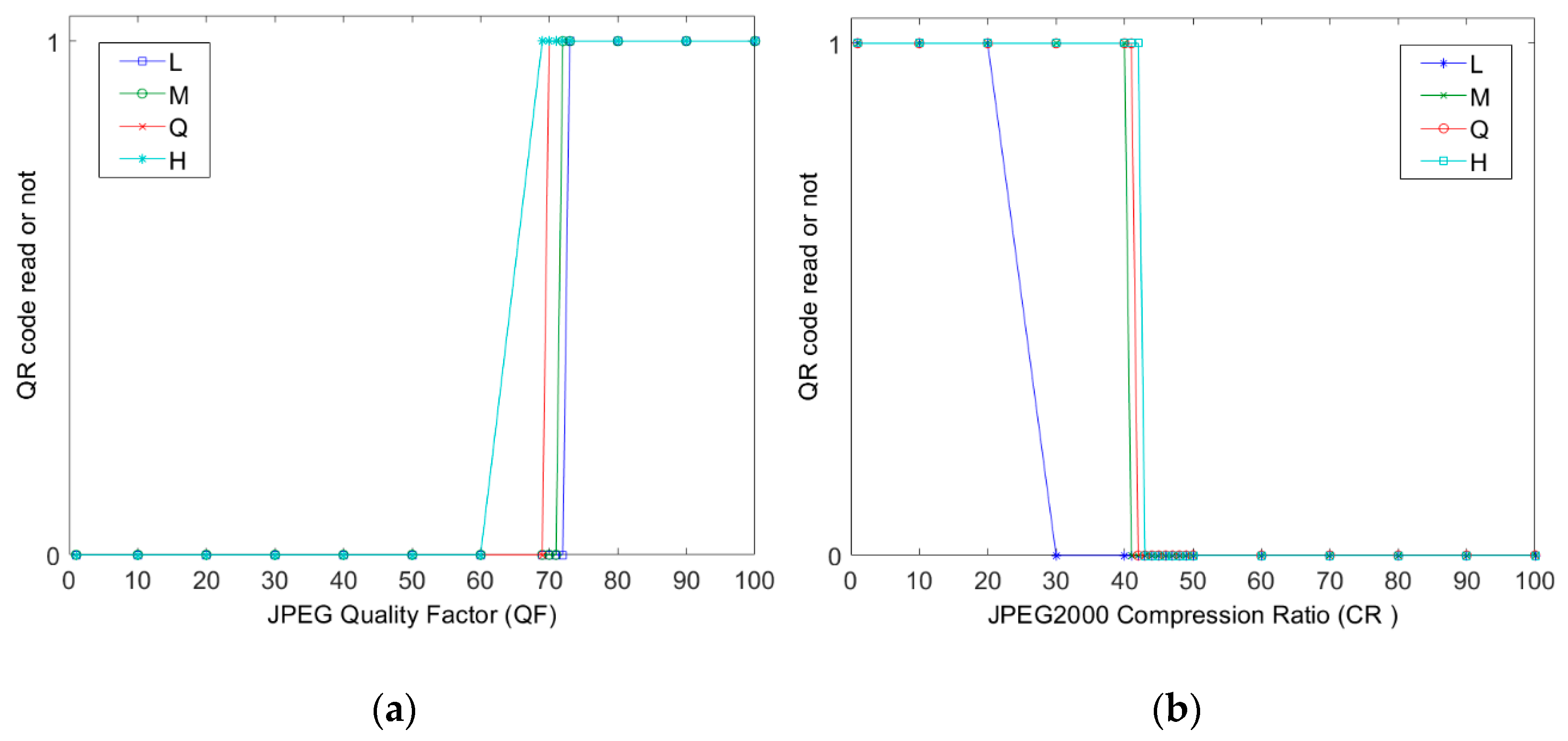
| Robustness to JPEG | High | Low | Low | Media | Low | High |
| Robustness to JPEG2000 | High | Low | Low | Media | Low | High |
Publisher’s Note: MDPI stays neutral with regard to jurisdictional claims in published maps and institutional affiliations. |
© 2021 by the authors. Licensee MDPI, Basel, Switzerland. This article is an open access article distributed under the terms and conditions of the Creative Commons Attribution (CC BY) license (https://creativecommons.org/licenses/by/4.0/).
Share and Cite
Juarez-Sandoval, O.U.; Reyes-Ruiz, L.J.; Garcia-Ugalde, F.; Cedillo-Hernandez, M.; Ramirez-Hernandez, J.; Morelos-Zaragoza, R. Additional Information Delivery to Image Content via Improved Unseen–Visible Watermarking. Electronics 2021, 10, 2186. https://doi.org/10.3390/electronics10182186
Juarez-Sandoval OU, Reyes-Ruiz LJ, Garcia-Ugalde F, Cedillo-Hernandez M, Ramirez-Hernandez J, Morelos-Zaragoza R. Additional Information Delivery to Image Content via Improved Unseen–Visible Watermarking. Electronics. 2021; 10(18):2186. https://doi.org/10.3390/electronics10182186
Chicago/Turabian StyleJuarez-Sandoval, Oswaldo Ulises, Laura Josefina Reyes-Ruiz, Francisco Garcia-Ugalde, Manuel Cedillo-Hernandez, Jazmin Ramirez-Hernandez, and Robert Morelos-Zaragoza. 2021. "Additional Information Delivery to Image Content via Improved Unseen–Visible Watermarking" Electronics 10, no. 18: 2186. https://doi.org/10.3390/electronics10182186
APA StyleJuarez-Sandoval, O. U., Reyes-Ruiz, L. J., Garcia-Ugalde, F., Cedillo-Hernandez, M., Ramirez-Hernandez, J., & Morelos-Zaragoza, R. (2021). Additional Information Delivery to Image Content via Improved Unseen–Visible Watermarking. Electronics, 10(18), 2186. https://doi.org/10.3390/electronics10182186