1. Introduction
The past few decades have seen extraordinary growth in wireless communication structure due to the approach of massive Internet of Things (IoT) and advanced real-time applications such as high-resolution video streaming, online gaming, vehicle-to-everything, self-driving vehicles, and other applications that are under development. However, these applications require high traffic-streaming bitrates and high quality of service (QoS), as well as a versatile network and flexible management technology. Unfortunately, the traditional radio access network (RAN) lacks enough flexibility, and, at the same time, the cost of network implementation will be high for the operators of the new application in traditional RAN. To overcome these challenges, the operators demand to contribute to the configuration of the mobile network by re-shaping the RAN network regarding their needs in order to achieve a cell network and equipment operating in a more software-driven, virtualized, flexible, intelligent, and energy-efficient way [
1,
2].
The O-RAN Alliance has introduced an Open RAN solution that allows the operators to manage the network implemented by components from multiple vendors. O-RAN has mainly been introduced to support the application of the 5G and NR. To achieve this goal, the O-RAN Alliance has made nine workgroups to cover the O-RAN architecture. Examples of these workgroups tasks are the Non-Real-Time RAN Intelligent Controller and A1 Interface, The Open Front-Haul Interfaces, Operations & Management (OAM), etc. Moreover, the Alliance has created O-RAN Focus Groups such as the Standard Development Focus Group, the Test & Integration Focus Group, the Open Source Focus Group, and the Security Focus Group. O-RAN is based on intelligence and openness principles, such as improved performance and agility and pushing towards an ecosystem of innovative, multi-vendor, interoperable, and autonomous RAN. Furthermore, O-RAN suggests open interfaces such as a front-haul interface that adopted a Split Option 7-2x from 3GPP specifications between the open distributed unit (O-DU) and open radio unit (O-RU) [
3,
4].
Split Option 7-2x enables flexibility in the implementation of O-DU and O-RU, so that vendors’ operational expenditures (OPEX) may leverage the wide range of network optimizations such as, for example, better beamforming configuration. Improving the capability of beamforming and beam handling is one of the hot topics of the O-RAN concept.
Based on O-RAN classification, beamforming can be implemented between O-DU and O-RU based on the Category A O-RU scheme and the Category B O-RU scheme. Our focus in this paper is Category B, where the advantage is that the front-haul bandwidth requirement should be comparatively low since it carries fewer bits, allowing many antennas without requiring high transport bandwidth. The challenge is that the O-RU design is more complex compared with Category A. If each O-RU measures beamforming matrices separately, there will be inter-RU interferences. However, using channel-information-based beamforming and applying zero-forcing precoding in O-RU, the inter-RU interferences can be eliminated.
This paper presents the definition, function, current research challenges, and evolution of O-RAN beamforming methods. We discuss the drawbacks of current implementations principles of O-RAN for achieving ultra-reliable low-latency communication in scenarios with noise and/or interferences by comparing the transferred packet size of C-Plane through the front-haul in different beamforming methods. The paper is organized as follows.
Section 2 presents the related work and the O-RAN architecture concepts, interface specifications, and units;
Section 3 focuses on splitting options and describes Split Option 7;
Section 4 elaborates our O-RAN beamforming approach, presents the beamforming challenges, and suggests methods focusing on one of the beamforming deployments (channel-information-based beamforming);
Section 5 explained the system models and simulation results; and lastly,
Section 6 overviews the paper conclusions.
2. Related Work
The packet structure of C-plane in O-RAN front-haul specifications has been discussed in “Overview of O-RAN Fronthaul Specifications” Anil Umesh, Tatsuro Yajima, Toru Uchino†, Suguru Okuyama, 2019, the O-RAN front-haul specifications that are expected to be the first standard to allow interoperability between various vendors. The paper introduced the packet structure of the U-, S-, and C-planes, where the author also touched on the benefit of small packet size in Category B and investigated Split Option 7-2x adopted in O-RAN front-haul, where the conclusion supports our proposal by confirming that the flexibility of hardware implementation in front-haul enables the low bandwidth requirement and high latency. In another research paper, “Hybrid beamforming designs for 5G new radio with front-haul compression and functional splits”, Jing Li, Dianwu Yue, Ha H. Nguyen, 2020, the authors investigated the implementation of hybrid beamforming in O-RAN and discussed the designed problem in both categories (A and B). This paper’s performance analysis and numerical results support our conclusions of using digital beamforming in Category B. It shows that the beamforming in the Category A scheme exceeds the beamforming in the Category B scheme in the large power management. Furthermore, the BF-B method is more sensitive to system parameter changes than the BF-A method, while it is less sensitive in small power management.
The challenges of the open radio access network are related to implementation. Until now, much of the documentation related to this issue has been about the architecture proposed by the O-RAN alliance and the specification of the open interfaces, which should ensure the interoperability of solutions provided by different vendors.
2.1. O-RAN Architecture
RAN architecture has been defined by 3GPP. Standards define, among others, RAN interfaces with user equipment (UE) and core network and include various RAN architecture options such as centralized RAN with ideal backhaul. The O-RAN Alliance followed the 3GPP specifications with the suggestion of new workflows on some units.
Figure 1 presents a holistic vision of the O-RAN architecture with the inclusion of key workflows for the functioning of beamforming. In the figure, all the names of the components include O-: to remark upon the openness of the solution. Such open architecture will provide an advantage to multiple vendors to develop concrete implementations of central units (CU), distributed units (DU), xApps and RAN Intelligent Controllers (RIC), etc. [
5,
6,
7].
As shown in
Figure 1, the internal structure consists of three main entities: the O-CU (Open-Central Unit), the O-DU (Open-Distributed Unit), and the O-RU (Open-Radio Unit). The O-CU and O-DU entities are connected by the F1 interface (mid-haul), and the O-DU is connected to O-RU by the front-haul interface. The configuration and split of these entities follow the 3GPP standards, which have proposed eight possible splitting options. We will give a short description of the O-RAN components defined by 3GPP standards with presenting the O-RAN specifications on the units and interfaces.
2.2. O-RAN Functional Units and Nodes
O-CU (Open Center Unit). The O-CU defined by 3GPP standards provides support for higher layers of the protocol stack. There is a single O-CU for each gNB. O-CU is connected to potentially multiple O-DUs via the F1 interface, while the O-DU is connected only to one O-CU. The centralized unit is a logical node that includes the gNB functions such as transfer of user data, mobility control, RAN sharing (MORAN), positioning, session management, etc. The O-CU performs the layer three functions, including radio resource control (RRC), packet data convergence protocol (PDCP), service data adaptation protocol (SDAP), etc., and operates on several interfaces such as X2-U, F1-U, NG-U, etc. [
8,
9].
O-DU (Open Distributed Unit). The O-DU is a commercial off-the-shelf (COTS) edge server that includes both baseband processing and radio frequency (RF) functions. It hosts radio link control (RLC), MAC, and a physical layer with network function virtualization or containers, as shown in
Figure 1. O-DU supports one or more cells, and each O-DU can support one or more beams to provide the operating support for O-RU by user (U), control (C), synchronization (S), and management (M) planes through front-haul interface [
10,
11,
12].
O-RU (Open Radio Unit). The O-RU hosts the lower PHY Layer Baseband Processing and RF Front End (RF FE), and it is designed to support multiple 3GPP split options. In O-RAN, the O-RU suggested being implanted based on Split Option 7-2x to achieve generic lower physical functions while avoiding impact from future 3GPP specifications changes. This should reduce O-RU OPEX and maintenance costs. The 7-2x split allows two types of O-RU radio categories in order to provide flexibility for a system designer, which will be able to implement the most suitable option depending on their needs. The first O-RU type is called Category “A”, and it hosts the precoding in the O-DU; the second type is the Category “B”, which hosts the precoding in the O-RU. This split has the benefit of hosting the beamforming in one unit, with the cyclic-prefix (CP) addition/removal and Fast Fourier Transform (FFT)/Inverse Fast Fourier Transform (IFFT) functions integrated with multiple-in multiple-out (MIMO), as shown in
Figure 1 [
10,
11,
12].
O-Cloud (Open-Cloud). O-Cloud is a cloud computing platform comprising a combination of physical infrastructure nodes that meet O-RAN requirements to host the relevant O-RAN nodes (i.e., Near-RT RIC, O-CU-CP, O-CU-UP, and O-DU). On the other hand, O-Cloud must support software components (such as operating system, virtual machine monitor, container runtime, etc.), management, and orchestration functions.
O-CU-CP (O-RAN Central Unit-Control Plane). The O-CU-CP is a logical node that terminates the NG-c, X2-c, Xn-c, F1-c, and E1 interfaces, besides the RRC and PDCP protocols across the UE by hosting RRC and control plane part of PDCP.
O-CU-UP (O-RAN Central Unit-User Plane). The O-CU-UP is a logical node that terminates the NG-u, X2-u, S1-u, Xn-u, F1-u, and E1 interfaces, besides the PDCP and SDAP protocols across the UE by hosting SDAP and User Plane part of PDCP.
Non-RT RIC (Non-Real-Time RAN Intelligent Controller). Non-RT RIC is a logical function inside the service and management orchestration (SMO) in O-RAN architecture and provides the A1 interface to the near-real-time RIC. Non-RT RIC provides policy-based guidance by supporting intelligent RAN optimization, machine learning (ML) model management, and enrichment information to enable O-RAN optimization. One of the important functions in non-RT RIC is the implementation of intelligent radio resource management in the non-real-time interval (i.e., greater than 1 s) [
13,
14,
15].
Near-RT RIC (Near-Real-Time RAN Intelligent Controller or nRT RIC). Near-RT RIC is a logical function that enables near-real-time control and optimization of E2 node functions and resources via fine-grained data collection and actions over the E2 interface with control loops in the order of 10 ms-1s. The specification can be found in O-RAN.WG3.E2GAP-v01.01. The near-RT RIC hosts one or more xAPPs that use the E2 interface to collect near real-time information (e.g., on a UE basis or a cell basis) and provides value-added services. The near-RT RIC control over the E2 nodes is steered via the policies and the enrichment data provided via A1 from the non-RT RIC [
13,
14,
16]. In this scheme, xAPPs are responsible for advanced functions such as handover and traffic steering [
15,
17].
SMO (Service Management and Orchestration). SMO is a consolidation of a wide range of management services. In a service provider’s network, SMO includes core management, transport management, end-to-end slice management, etc. [
11]. The fundamental capabilities of the SMO that provide RAN support in O-RAN are (1) fault, configuration, accounting, performance, security (FCAPS) interface to O-RAN network functions; (2) non-RT RIC for RAN optimization; and (3) O-Cloud management, orchestration, and workflow management. As shown in many publications, security and accountability are crucial issues of the Open RAN initiative [
18,
19].
2.3. O-RAN Interfaces
O-RAN specifications adopted the interfaces from 3GPP standards.
Figure 2 shows the interfaces of 3GPP that include suggested functionalities for the realization of full beamforming in O-RAN architecture. The 3GPP standards define E1, F1-c, F1-u, NG-c, NG-u, X2-c, X2-u, Xn-c, Xn-u, and Uu interfaces. In contrast, O-RAN defined A1, E2, and open front-haul as functional interfaces and defined O1 and O2 as management interfaces for SMO [
9,
20].
The A1 interface is located between non-RT RIC and near-RT RIC. A1 allows non-RT RIC to provide (to near-RT RIC) three types of services: a policy management service, an enrichment information service, and an ML model management service.
The E2 interface is a logical interface connecting the near-RT RIC with an E2 node. An E2 node is connected to only one near-RT RIC, while a near-RT RIC can be connected to multiple E2 nodes. The protocols over the E2 interface are based only on the control plane and supports near-RT RIC services and functions, where they can be used to control what is happening within that base station.
The O1 Interface is located between O-RAN managed element and the management entity.
The O2 Interface is located between the SMO and O-Cloud (managing the platform resources and workload).
The
open front-haul interface is located between O-DU and O-RU and is specified by WorkGroup 4 of O-RAN Alliance. O-RAN front-haul specifications include a new provision framework for functional splitting called Split Option Split 7-2x, which is placed in O-RU (baseband processing section). Front-haul also directs the control, user, synchronization, and management plane signals from O-DU to O-RU that define the enhanced common public radio interface (eCPRI) framework. Finally, the O-front-haul prescribes detailed signal formats and equipment operation required for O-RAN [
20]. The four planes of the front-haul are the following:
The
C-Plane (control plane) is a frame format that carries data used in control user data scheduling, beamforming weight selection, numerology selection, etc. In the C/U-Plane, the O-RAN front-haul specifications support a protocol stack used by the enhanced common public radio interface (eCPRI) or radio over ethernet (RoE). The eCPRI sends information specifying beamforming weights from the O-DU to O-RU. Other information includes time resource and frequency resource information (startPRBc, numPRBc) [
21,
22].
The
U-Plane (user plane) is a frame format that carries the user data messages between O-DU and O-RU, such as the in-phase and quadrature-phase (IQ) sample sequence of the orthogonal frequency division multiplexing (OFDM) signal. In the same way as the C-Plane, the data can be optionally transmitted over IP Layer 3, and the eCPRI header contains information such as message type, eCPRI payload size, message source and destination identifiers, and message sequence number [
21,
22];
The
S-plane (synchronization plane) includes synchronization messages used for timing synchronization between O-DU and O-RU over the Ethernet. In O-RAN front-haul specifications, the S-plane relies on the precision time protocol (PTP) (IEEE 1588-2008) to achieve high-accuracy synchronization on the O-RU side by synchronizing with the high-performance clock installed at the O-DU side [
21].
The
M-Plane (management plane) includes messages used to manage the radio unit functions. In the O-RAN front-haul specification, the M-Plane provides various parameters as data models to FCAPS functions on the O-RU side as required by the C/U-Plane and S-Plane. This data model eliminates dependence on each O-RU vendor’s implementation and makes a real multi-vendor Open RAN possible [
23,
24].
O-RAN front-haul specifications have been discussed in [
25], where Umesh, Yajima, Uchino, and Okuyama introduced Split Option 7-2x adopted in the O-RAN front-haul and described the C-Plane packet prescribed in the same specifications. These specifications are expected to be the first standard to enable interoperability between different vendors.
3. Challenges of Implementation: Splitting Options
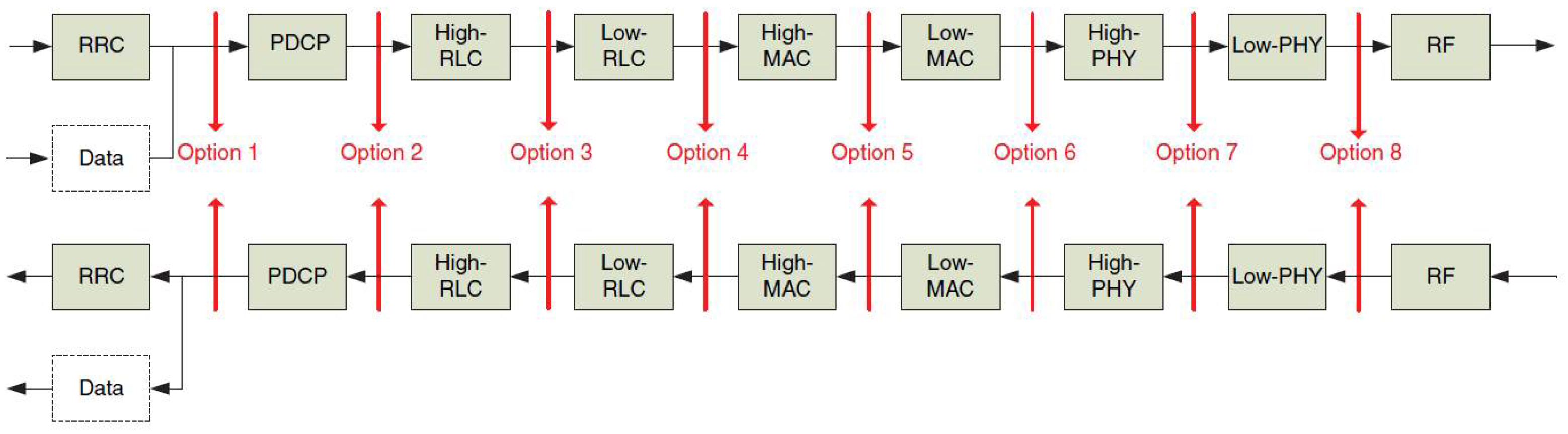
3GPP defined and proposed eight possible splitting options. Splitting options are all the possibilities of separating modules in the RAN (between distributed and central units) so that each option defines (and standardizes) specific interfaces with different functionalities between CU and DU, as shown in
Figure 3. These splits provide high flexibility to implementation since they allow the coordination between performance features, load management, and real-time performance optimization. In addition, they allow underlying technologies (SDN/NFV) and adaptation to various use cases by utilizing the configurable functional splits (e.g., variable latency on transport applications). The various splits supported new services, deployed on general-purpose or specialized hardware, with functions ideally placed to maximize scalability as well as spectrum and energy efficiency. The option adopted by O-RAN Alliance is Split Option 7 and, specifically, Split Option 7-2x [
26,
27,
28,
29].
Split Option 7 assumes splitting at the physical layer function while maintaining radio functions (RF) at the DU. One of the key techniques in this spit is the compression technique, which allows the reduction in transport bandwidth requirements between the DU and CU; furthermore, it allows the possibility of multiple configurations, which are known as options 7-1, 7-2, and 7-3 [
30].
In Option 7-1, the FFT, cyclic-prefix (CP) removal, and possibly PRAC filtering function, resides in the DU within the uplink block diagram; the rest of the PHY functions reside in the CU. In the downlink block diagram, inverse fast Fourier transform (IFFT) and CP addition functions reside in the DU, and the rest of the PHY functions reside in the CU. The main benefit of this option is that it allows the implementation of advanced receivers.
In Option 7-2, the FFT, CP removal, resource de-mapping, and possibly pre-filtering functions reside in the DU within the uplink block diagram; the rest of the PHY functions reside in the CU. In the downlink block diagram, inverse FFT, CP addition, resource mapping, and precoding functions reside in the DU, and the rest of the PHY functions reside in the CU. Overall, this option has some drawbacks, such as the high bandwidth requirements, relatively high latency requirements, and complex timing for the RU and CU/DU link. However, it has been modified to be better than Split Option 7-1 in the case of high bandwidth requirements [
31].
In Option 7-3 (only for downlink), only the encoder resides in the CU, and the rest of the PHY functions reside in the DU. The main benefit is that it reduces the front-haul requirements in terms of throughput to the baseband bitrates, as the payload for Option 7-3 is encoded data. This split has a high bandwidth requirement, relatively high latency requirements, and complex timing for the RU and CU/DU link.
The O-RAN specification adapts Split Option 7-2x for front-haul specificities. The main goal is to reduce O-RU OPEX and maintenance costs. In comparison with Split 7-2, Split 7-2x has a simplified interface, an open interface protocol specifically designed to enable interoperability between RUs and DUs from different vendors, and there is not complex timing for the RU and CU/DU link.
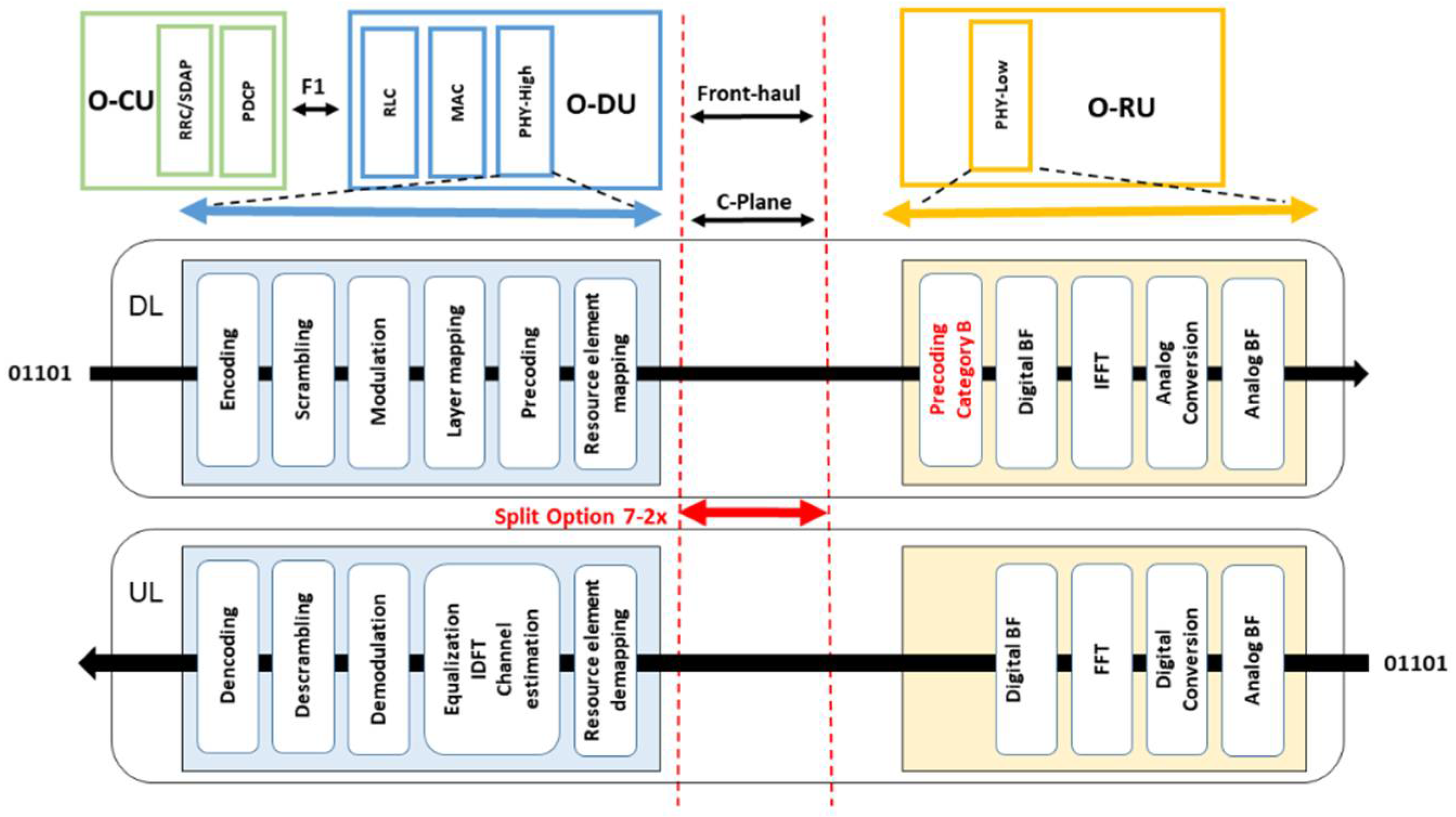
In Split 7-2x, the downlink and uplink processes flows are shown in
Figure 4. The user bit sequence received from the MAC layer to PHY-High is processed into the O-DU. The O-DU operates through encoding, scrambling, modulation layer mapping, precoding (precoding can be paced in O-DU or O-RU), and resource element mapping (antenna mapping). Then, the outcome results need to be operated by the PHY-Low layer in O-RU through the IQ sampling sequence of an OFDM signal in the frequency domain. This sequence is then subjected to IFFT processing, converted to an OFDM signal in the time domain, and converted to an analog signal. The beamforming is performed in this flow to be placed before IFFT in case of digital beamforming and after analog conversion in case of analog beamforming.
Split Option 7-2x implements functions up to the resource element mapping in the O-DU and supports both precoding in O-DU (Category A) and precoding in O-RU (Category B).
Category A: the precoding (digital beamforming) function is performed in O-DU, allowing the O-RU design to be simple. The front-haul interface will carry spatial streams in the downlink. Category A fits well in the case of low-frequency and latency-insensitive services.
Category B: precoding (digital beamforming and analog beamforming) is performed in O-RU, which makes the O-RU design complex, and the front-haul interface will carry spatial layers. The advantage of this category is the reduced downlink throughput achieved thanks to modulation compression in the downlink so that only the bits equivalent to the constellation points are sent there. Category B fits well for high-frequency and high-traffic networks [
32].
In Split 7-2x, the uplink process supposes that the signal received in the time domain by the O-RU is digitally conversed, FFT-processed, and IQ-sampled in the frequency domain. Then, the signal will access the O-DU through resource element demapping, equalizing processing, inverse discrete Fourier transform (IDFT) processing, and channel estimation, demodulation, descrambling, and decoding. Then, the user bit sequence will be sent to the MAC layer. The beamforming is placed after FFT processing in the case of digital beamforming and before digital conversion in analog beamforming.
As we explained above, one of the advantages of Split Option 7-2x is to reduce the front-haul required bandwidth caused by over-sampling applied to the OFDM signal in the time domain. This reduction can be higher when more functions are assigned to the O-RU. For example, in the case of downlink, placing the precoding in O-RU can prevent an increase in the required front-haul bandwidth when the number of MIMO spatial streams is greater than the number of MIMO layers. Another example: when performing resource element mapping/demapping on the O-DU side, data will be transmitted after user multiplexing through simplifying control signals on the Front-haul so that it may be simpler to achieve multi-provider RAN [
26,
29].
4. O-RAN Beamforming
Beamforming has been introduced with great benefits to overcome several communication challenges, such as enhancing the precision of radio connections, increasing throughput, increasing the number of parallel connections in a given cell area, and saving energy consumption during transmissions. In mmWave transmission, beamforming is particularly beneficial to improving the signal-to-noise ratios (SNR) through direct targeting of user groups, mainly indoor coverage; further, beamforming also may nullify the interference between UEs singles in high-density environments. All these benefits have put the developers, testers, and antenna designers in the face of other challenges, such as cost of implementation, design complexity, and the testing methods that should be done in an actual physical environment. However, all these challenges have been taken into consideration with 3GPP and O-RAN specifications. 3GPP has introduced the split options that helped the designers achieve fixed implantation of the RAN. O-RAN adopted the Split 7-2x option, which introduces simplified communication interference between O-RAN units, especially in front-haul, where the C-plane communication carries the beamforming data in several beamforming methods. O-RAN has supported all beamforming technologies (digital, analog, or hybrid) in the front-haul interface.
Figure 5 describes the block diagram of the popular beamforming solution in O-RAN, which is hybrid beamforming.
As we mentioned in
Section 3, O-RAN has adopted Spit Option 7-2x in the front-haul interface that required a high bandwidth. To overcome this challenge, we suggest using Category B to perform the precoding in O-RU. This implementation will lead to inter-RU interferences in O-RU, because each O-RU will calculate beamforming matrices individually. Thus, it has been suggested to design the beamforming matrices in O-DU through the estimated channel information and generate a precoding beam in O-RU. We propose the use of the zero-forcing (ZF) algorithm as a possibility to reduce the interference in received signals while maintaining the beamforming in only one unit (thanks to the introduction of the precoding into the O-RU unit). Thus, the cost of implantation and hardware complexity will be reduced [
29,
32,
33,
34,
35].
4.1. O-RAN Beamforming Methods
The following are the methods proposed by O-RAN in order to achieve acceptable performance in beamforming:
Beamforming indexing method (predefined-beam beamforming). O-DU sends information about the beamforming type to the O-RU predicated on BeamID, and the O-RU stores this information in a table of beam indexes. This table contains beam weights, which could be frequency domain beam weights (digital beamforming), time-domain beam weights (analog beamforming), or both of them as hybrid beamforming; the BeamID is utilized as a pointer to a pre-defined beamforming weight vector. Therefore, BeamID is only a weight vector value exchanged between O-DU and O-RU to indicate which beam should be applied.
Real-time weights method (weight-based dynamic beamforming). In this method, the O-DU sends the beamforming weights generated in real time to the O-RU to be associated with a specific user’s data. A beam index can be assigned (and utilized in subsequent messages) if the beamforming weights are stable for a period of time. There are two implementation cases in this method: weight-based dynamic (digital and analog) beamforming and weight-based dynamic hybrid beamforming; in the first case, the beamforming weights can be updated in real time with the BeamID value associated with the weights. In the second case, two sub-cases are considered: (1) both the frequency-domain and time-domain weights may be updated in real-time, and (2) the frequency-domain weights may be updated in real-time, and the time-domain beams are fixed. Let us remark that frequency domain weights are applied to the frequency domain IQ data per section, and the time domain weights are applied to the time domain IQ data per OFDM symbol.
Beam attributes method (attribute-based dynamic beamforming). The main drawback of the previous method is that it requires additional processing capability in the O-RU for adjusting transmission to the beam weights provided by the O-DU. Therefore, a modification to the previous method has been proposed so that we obtain the beam attributes method. The modification is that the O-RU is in charge of generating the beamforming weights using a set of beam attributes signaled by the O-DU and carried (to the O-RU) by the control plane. These attributes are (1) azimuth and elevation, (2) beam width (narrow, wide), (3) side lobe suppression, and (4) beam weights calculated by RU. The consequence of the generation of beam weights by the O-RU is that the hybrid beamforming is not allowed in the beam attributes method. The reason is that the weights generated by O-RU will be either frequency-domain or time-domain but not hybrid.
Channel information method (channel-information-based beamforming). This method is based on digital beamforming. It is known that digital beamforming is a good solution for capacity and flexibility in the case of a high-traffic communication environment since it offers steerable beams. Each antenna has a dedicated RF signal and path and provides a high number of beams that can be transmuted dynamically with no change in the hardware. Thus, in this method, the O-RU generates beam weights based on the channel information from O-DU. The algorithms can synthesize a drive signal to obtain the maximum of any beam characteristics. However, implementing the precoding in RU will lead to inter-RU interferences in the O-RU. The zero-forcing algorithm (ZF) is one of the algorithms that can be implanted to overcome this interference issue in received signals.
4.2. Open Research Issues
The new applications identified in the 5G charter may face challenges in latency with the current O-RAN structure, specifically in the ultra-reliable low-latency communication (URLLC) scenarios such as vehicle-to-everything and boundless XR (e-health), which demand ultra-low latency. The problem lay in determining whether the front-haul open interface (communicating the O-DU and O-RU) is capable of meeting strict requirements for ultra-low latency applications, which implies practically zero interferences in the interface.
In order to avoid interferences, we propose to implement beamforming by using the channel information method combined with the zero-forcing algorithm. The O-DU will estimate the channel information between O-RU and users and pass this information on as channel matrix information to O-RU through the C-Plane. The implementation of this method is based on Split 7-2x Category B, where the precoding will implement in O-RU in the case that the precoder output streams are over 8.
4.2.1. Fronthaul Model Concept
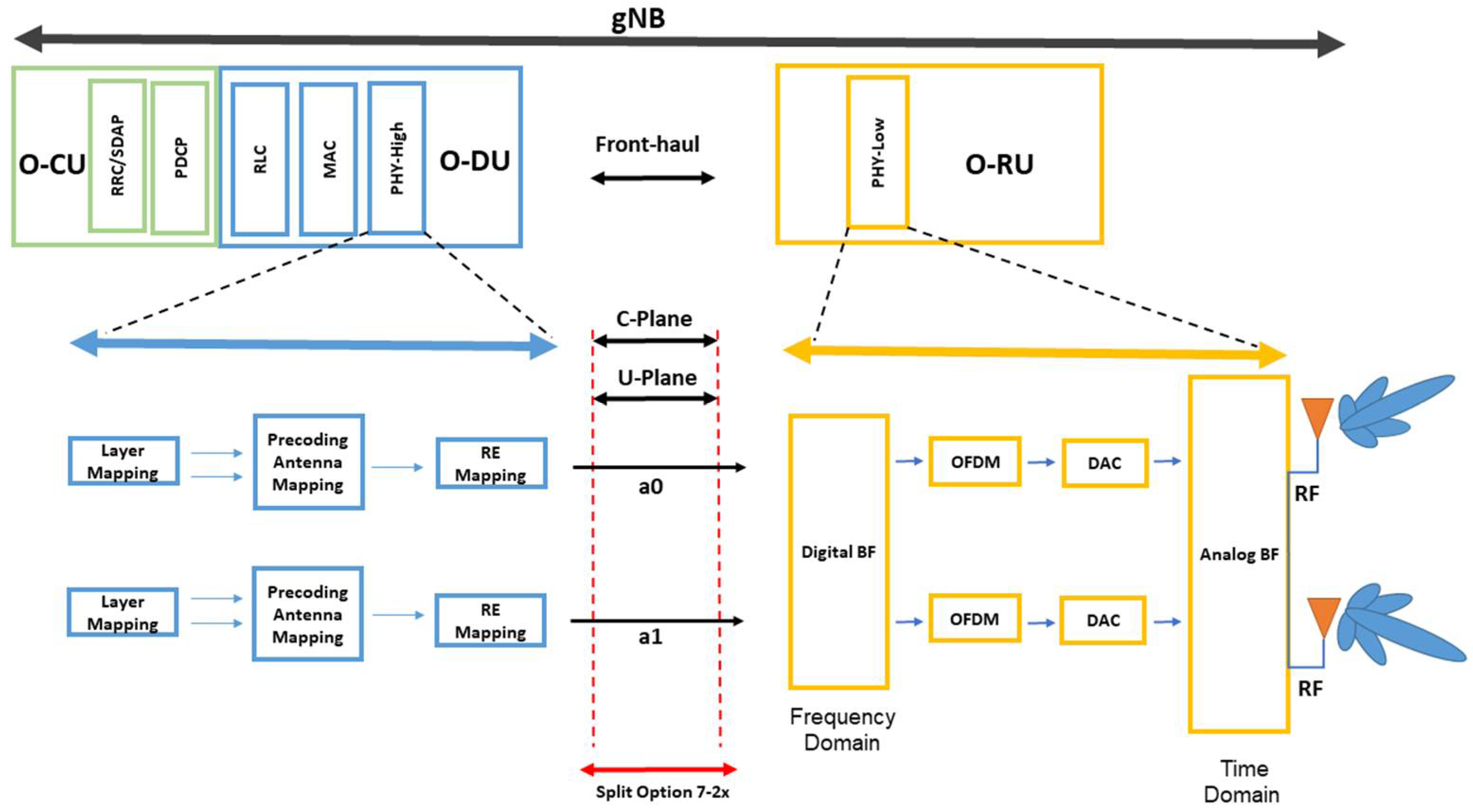
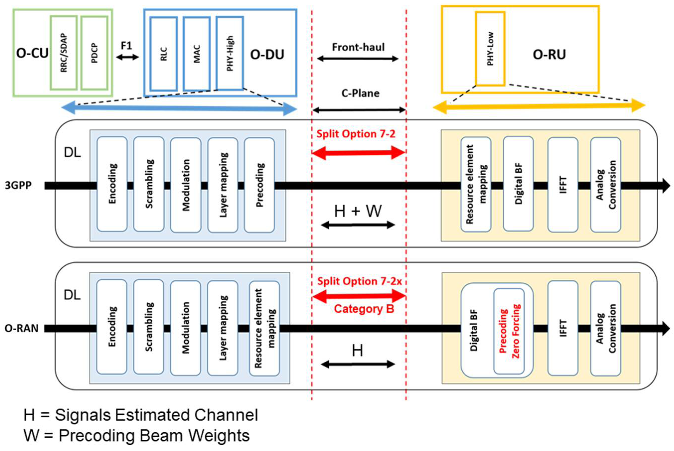
This is a new specification that O-RAN has introduced, which will allow the front-haul interface to carry spatial layers, which means fewer data and reduces the complex timing for O-RU and OCU/O-DU link compared to the 3GPP specifications.
Figure 6 shows the digital beamforming diagram in O-RAN compared to 3GPP.
The comparison in
Figure 6 shows the difference in the implementation of digital beamforming between 3GPP and O-RAN (Category B), where the precoding has been moved to O-RU. Thus, this implementation will achieve more reliability due to the low channel load in the data flow from O-DU to O-RU, where the link’s capacity requirement will be less by reducing the data bit of scheduling and beamforming commends as its one of the main contents in C-plane data flow between the O-DU and O-RU, as shown in
Table 1.
C-Plane messages have two layers. The first layer is the transport layer, and the eCPRI header including corresponding entries implemented to indicate the message type. The second layer is an application layer including required fields for control and synchronization; moreover, within the application layer, some sections define the characteristics of the U-plane. Each section transfers specific parameters to O-RU individually. There are more than eight sections in C-plane. Each section has a set of parameters that carry the data between O-DU and O-RU. These parameters are managed by M-Plane and can specify the packet size of the C-pane based on the used section from O-DU and O-RU, as shown in
Table 2.
As shown in
Table 2, each section has multibit parameters with different numbers of bits. Some of these parameters specify the beamforming method; for example, the weight-based dynamic beamforming method implements the beamforming in O-RU based on parameters carried by the C-plane and transferred from O-DU through the front-haul, such as precoding beam weights (carried by the BeamID parameter,
Section 1 and
Section 3) and channel state information (carried by ciIsample and ciQsample parameters,
Section 6). The C-plane packet in this implementation carries more parameters, leading to a high signal cost due to the high number of bits, as shown in
Table 2. On the other hand, in the channel state information beamforming method, the C-plane packet will carry fewer parameters and reduce the packet size by 40% by abandoning the BeamID parameter and generating precoding beam weights in O-RU (Category B) based on parameters transferred from O-DU such as UE identifier (ueId parameter—
Section 5) and channel state information (ciIsample and ciQsample parameters—
Section 6).
Additionally, the basic calculation formula can explain and compare the results of reducing the transferred parameters is to calculate channel capacity in the front-haul by using the celebrated Shannon formula
where
is the channel bandwidth of the front-haul interface,
is the average signal power, and
is the average noise power.
Reducing the transferred parameters leads to the use of fewer recourse blocks, which will raise the average output power of the signal. This concept is important in the channel state information beamforming method to achieve a lower packet error rate and high latency in order to support the complexity of generating the beamforming weight in O-RU, which required high performance of CSI data transferred from O-DU. The outcome results of this concept can prove that the channel state information beamforming method is considered a good choice in high channel traffic to improve the latency and channel capacity by using fewer recourse blocks and increasing the signal power compared to the other three beamforming methods mentioned above.
4.2.2. Zero-Forcing Beamforming Model Concept
Implementing the precoding in O-RU will cost high complexity in the case of a high precoding stream number, leading to inter-symbol interference in O-RU by interference with non-desired users. To overcome this interference, we propose using zero-forcing beamforming.
Zero-forcing beamforming (ZF-BF) is a method that is widely considered in massive MIMO systems [
36]. The simplest approach is to invert the channel through the pseudo-inverse, which is referred to as ZF precoding; this technic allows transmitting and receiving data to desired users and nullifying the directions from the interference users. ZF-BF performance depends on the accuracy of received channel status information (CSI) from each user to determine the precoder and beamforming weight vector. This channel, also called estimated channel information, carries the information of the signal properties such as propagation features from the transmitter to the receiver, scattering, fading, and power decay with distance [
37,
38,
39].
5. System Model and Simulation Results
Let us assume the downlink MIMO channel between a base station with multiple transmit antenna M that serve
K active independent single-antenna users, where the number of active users K is approximately equal to N (
) and the users are scheduled individually of their channel conditions. At the base station, we consider that we have a transmission sequence [
] transmitted per each time slot, these sequences can be grouped based on the number of transmit antenna (e.g., if we have two transmit antenna the
send by the first time slot and
send by the second time slot, and so on). For a discrete-time model, a transmitted signal is denoted by the
transmitted vector
where
is the transmit beamforming weight vector for user
, and
is a transmitted symbol for user
. The received signal vector obtained by user
is given by
where the
channel vector for user
is
, and
denotes complex conjugate, and
is the vector of noise (additive white Gaussian noise with zero mean and variance
). Channel vector
between the user and base station can be exported as
where the
and
denotes the distance and path
-loss between base station and user
. Interchanging
into
obtained a received signal given as
From the transmit power constraint for user
which is
we can calculate the interference caused by other users through the received SINR of the
-th user
The ZF-BF precoding is closely related to the concept of generalized inverses in linear algebra, where each beam generated by the ZF-BF precoder is orthogonal to all the other user channel vectors [
36]. In the destination direction, we need to calculate the inverse of channel matrix
and, for this scope, we applied the well-known Moore–Penrose inverse generalization to obtain
and assumed
denotes an
matrix whose columns are transmit beamforming vectors; then, the ZF precoding vectors can be expressed as
The ZF precoding condition of generating
precoder for user
is orthogonal to all the other users’ channel vectors
such that there is no interference from other users where
; the received SINR for the
k-th user is determined as
We can use the
tool to simulate the SINR for
k-th users by assuming a downlink mMIMO system with 16 transmit antennas and four active users; each user has one single antenna. This assumption is justified since the implementation of UE is determined by the requirement for low complexity, cost, and power consumption. The base station interfaces with each UE through two scenarios: the first is the BS interfaces with UE by one beam stream so that the total number of streams is
, and the second scenario is that the BS interfaces with each UE with multi-beam stream
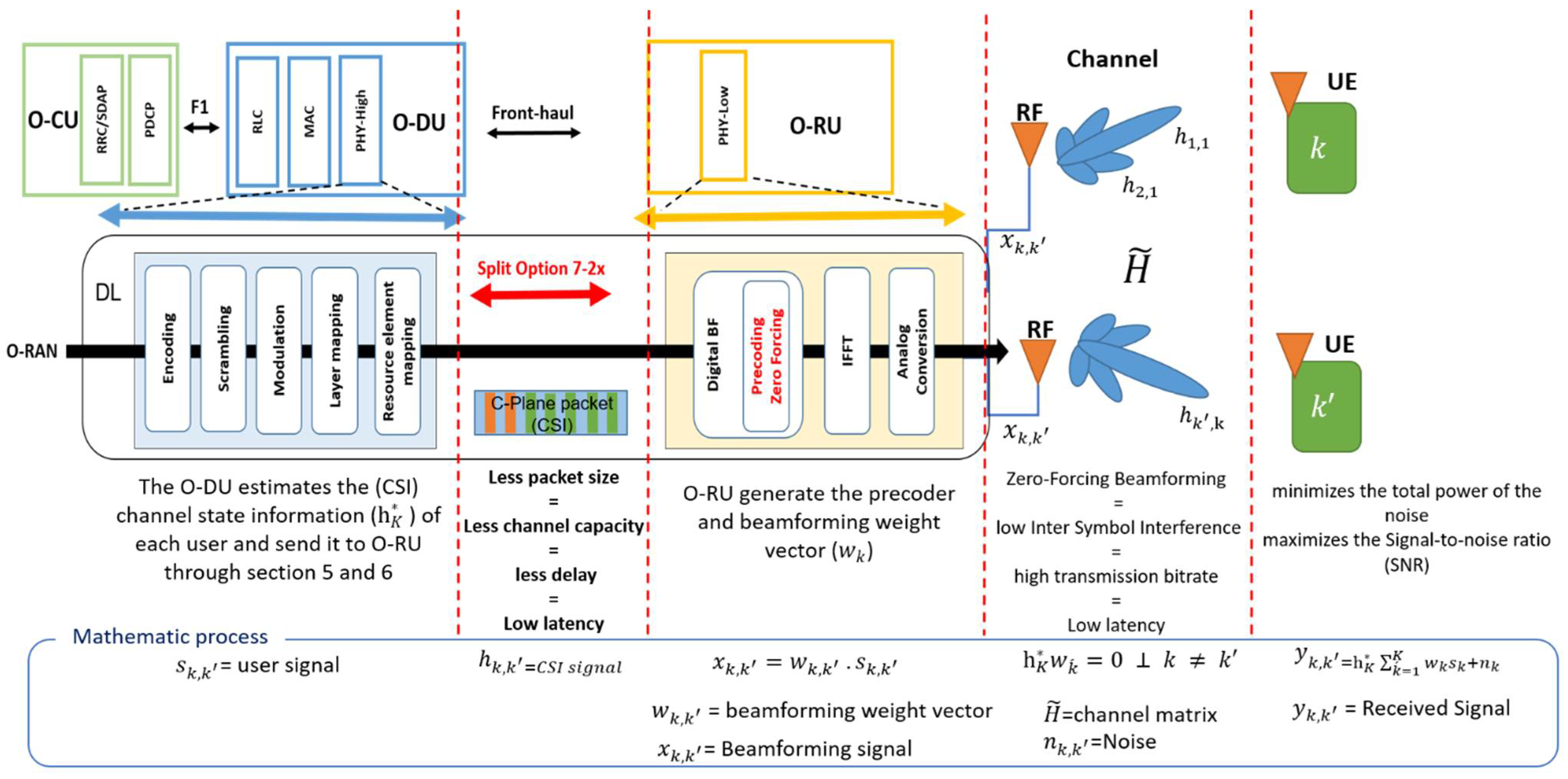
; this can be achieved by allowing spatial multiplexing and multi-user MIMO. Additionally, to achieve more simplicity, we consider a Rayleigh fading channel between the BS and users with variance SNR up to 30 dB. The system diagram can be explained more simply in
Figure 7.
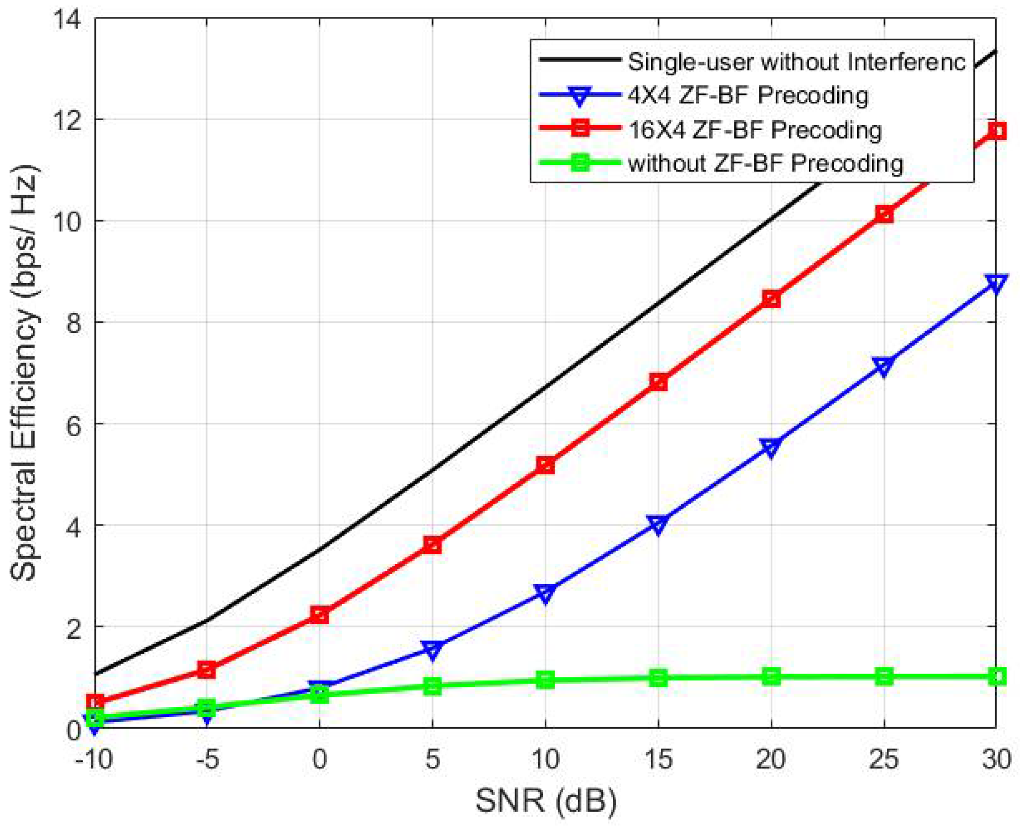
The channel state information beamforming method required to generate the beamforming weight vector in O-RU was based on CSI of the user and in the case of high channel traffic, the ZF-BF allows obtaining a separate received signal at each user that minimizes the total power of the noise and, as a consequence, maximizes the signal-to-noise ratio (SNR). Obviously, the method also minimizes the inter-symbol interference (ISI) components in the output (it drives the ISI to zero in a theoretical noise-free cause interference).
From
Figure 8, the results show that the SINR is not sufficient when no precoding is applied, while the achievable rate achieved by the zero-forcing beamforming approaches is adjacent to the more complex digital system. Moreover, the zero-forcing beamforming can achieve a performance adjacent to the single-user scenario, which means it can reduce the interference from the multi-user environment. The simulations show the comparison in the implantation of ZF precoding in O-DU, where only four antennas served four active users, and the implantation of ZF precoding in O-RU with mMIMO channels reduces multi-user interference.
The zero-forcing algorithm could achieve a high reduction of interferences in the channel interface so that the high transmission bitrate needed in the interface may meet low latency requirements by using the advantage of low latency in the front-haul interface, as shown in
Figure 6. The second point to be analyzed is whether the channel information method itself also meets the low latency requirements. This is the second open issue that needs to be investigated before the deployment of beamforming in URLLC scenarios.
In addition, the O-RAN has promised to provide flexibility in the network implementation, and by using the advantage of Split Option 7-2x with Category B, we could (and should) optimize the channel status information (CSI) in the front-haul. For this, several equalizers combined with machine learning technology should be investigated. At last, information from the user equipment could be used in machine learning algorithms in order to optimize (in both performance and simplicity) the functioning of the beamforming.
6. Conclusions
This paper has positioned the research to be performed for the implementation of beamforming in O-RAN while meeting the requirements of low latency. We started by presenting the O-RAN architecture and the configurations of the interfaces between O-RAN units and presented the Split Option 7-2x. We have analyzed beamforming methods in O-RAN and discussed the best method for ultra-reliable low-latency communication. The discussion concludes that the channel information method seems to be the best positioned for minimizing latency since it uses digital precoding implemented in the O-RU (O-RU Category B) and makes feasible the implementation of ZF-BF that may reduce decisively the interference in received signals, so that the O-RU may operate without interferences. Moreover, we introduced open issues to be studied when using the channel information method in order to optimize channel status information.


 ,
, 


