Abstract
Energy storage systems (ESSs) are gaining a lot of interest due to the trend of increasing the use of renewable energies. This paper reviews the different ESSs in power systems, especially microgrids showing their essential role in enhancing the performance of electrical systems. Therefore, The ESSs classified into various technologies as a function of the energy storage form and the main relevant technical parameters. In this review paper, the most common classifications are presented, summarized, and compared according to their characteristics. A specific interest in electrochemical ESSs, especially battery energy storage systems, focusing on their classifications due to their importance in the residential sector. Besides that, the benefits and drawbacks of Lithium-Ion (Li-Ion) batteries are discussed due to their significance. Finally, the environmental impact of these ESSs is discussed.
1. Introduction
At the beginning of the 2000s, scientific research in the field of energy storage systems (ESSs) has been developed and increased significantly. Figure 1 shows the publications per year according to the Scopus analysis on ESSs. Analyzing the papers that were published recently, it has been found that many of the review research papers in ESSs are focusing only on the classification of ESS. Sometimes, the classification is varied from one paper to another. Other papers are summarizing the applications of ESSs, and another includes the environmental impact of ESSs. For instance, in [1], ESSs are classified into mechanical, chemical, electromagnetic, and thermal storage. However, in [2] ESSs are divided into six categories: mechanical, thermal, chemical, electrochemical, electrical, and hybrid systems. ESSs are divided into electrochemical, electromagnetic, thermodynamic, and mechanical in [3]. Reference [4] focus on the environmental impacts of ESSs. Therefore, it is vital to make this review include different groups of ESSs commonly used in microgrids during this period classifying them according to their physical form and technical characteristics. Also, including their applications and environmental impact in the review paper. Energy storage is the formation of different styles of energy at one time, which can be used for some useful operations at different times. Generally speaking, electric energy needs to be transformed into another form of energy that can be stored. Energy can be stored in various forms, such as chemical, electrochemical, electrical, mechanical, and thermal systems. A better way to store energy is essential to improve energy storage efficiency. One of the keys to the progress of energy storage is to find new materials and understand the functions of current and new materials.
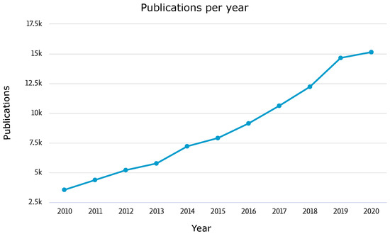
Figure 1.
Scopus analysis on energy storage systems researches in the last 20 years.
A microgrid is a small-scale power grid that can operate independently (Isolated mode) or collaboratively with the power grid (Grid-connected mode), enabling net power flows with the distribution network. The essential elements within a microgrid are the loads, the generation systems, either dispatchable generators or renewable energy sources, power electronic converters, and protection devices. The most significant share of renewable energy sources in microgrids is based on solar photovoltaic or wind turbine generation. Both sources rely on natural phenomena such as solar irradiance or wind speed. With the increasing penetration of renewable energy sources, the stability and the reliability of the microgrid are affected as those energy sources are intermittents [5,6].
However, the continuous development of ESS [7,8] balances the stochastic behaviour of both the renewable energy sources and the power demanded at the microgrid, ensuring an uninterrupted and stable power flow to the loads [9,10,11].
The benefits of integrating ESSs in electrical power systems have been widely increased. This is due to the fact that renewable energy is intermittent and not always reliable in power systems, which is influenced by natural factors. ESSs are solving the intermittent drawback of renewable energy and increase the reliability of the power system. Also, ESSs provide more advantages, for instance, peak shaving, valley filling, etc. This discussion aims to demonstrate how these ESSs play a key supporting role in the performance of electric systems. Even though these benefits are valid from large-scale generation down to the end-user applications, in particular, the benefits of ESS in microgrids are targeted here [12,13,14]:
- From the point of view of the generation, ESSs allow for:
- -
- Maintaining uninterrupted and stable power flow to the loads [9,10,11,15]: Due to the penetration of renewable generation sources, ESS is needed to provide power when the renewable sources are not able to supply energy to the system.
- -
- Providing peak shaving/load levelling [5,14,16,17,18,19]: The ESS enables the system to store the surplus energy during the light load and low price of energy periods and to provide the required energy at heavy load intervals and high price periods.
- -
- Giving support for black-start and reduce the risk of blackouts [5,6,14]: The black-start occurs when the system needs to be restarted after a blackout (collapse of failure or large power outage). It has been reported how some specific technologies (e.g., electrochemical batteries and supercapacitors) have the capability of achieving such restoring features [20].
- -
- Enabling the use of mobile/remote applications [20]: It provides power for remote areas or stand-alone systems such as electric vehicles and portable devices.
- At the transmission level, ESS provides for:
- -
- Postponement of infrastructure upgrades and congestion relief [12]: The usage of ESS reduces the need for new investments in order to have a suitable transmission capacity.
- -
- Voltage Regulation [13]: ESS allows for stabilizing the voltage levels between each end of the power lines in the system.
- Finally, at the distribution level and end-user services, the implementation of ESS yields to:
- -
- Improving the power quality [5,12,15,16,17,21,22,23]: In order to effectively minimize the effects of power quality issues (instantaneous voltage drop, transients and flicker, sag, swell, and harmonics), it required a fast response of the ESS. Supercapacitors, superconducting magnetic storage systems, and flywheels have a very fast response, within the range of milliseconds. These dynamics are followed by the performance of batteries, with characteristic responses in the order of seconds [20].
- -
- Increasing reliability [12,16,17]: ESSs support customer loads in the case of the loss of total power.
- -
- Providing voltage support [17]: Maintain the voltage within an acceptable range.
- -
- Postponement of the infrastructure upgrades [12]: Utilizing ESS reduces the need for new investments to have suitable distribution capacity to meet the increasing load demands. ESSs can mitigate the congestion and thus help utilities to postpone or suspend the reinforcement of the distribution network. This can be done using peak shaving.
- -
- Ride-through support [17]: ESS can provide energy to ride-through operation after disconnection due to a fault in the system and fault clearance.
In order to determine the optimal ESS technology for a given application, the requirements in terms of minimum response time and minimum discharge time need to be characterized. Table 1 shows the minimum response time needed and the minimum discharge duration of the key applications of the ESSs [12,21].

Table 1.
The minimum response time and discharge time of the applications of the ESS.
The structure of this paper is organized as follows: Section 2 explains the different ESSs depending on how the energy is stored. Then, classification based on characteristic time is discussed in Section 3. After that, Section 4 focuses on batteries electrochemical ESSs as it is one of the most ESSs widely used in several applications. Sequentially, Section 5 shows the environmental effect of different ESSs. Finally, Section 6 summarises the conclusions and illustrates the future trends in this topic.
2. Energy Storage Systems Technologies
In this section, a summarized review of the different ESS technologies suitable for electrical system applications is carried out. Depending on the physical form and mechanism in which the energy is stored, the energy stored could be mechanical, electrical, chemical, electrochemical, and thermal form. A first classification established as follows [12,21,24,25,26,27,28,29]:
- Mechanical Energy Storage System: The energy is stored in the form of kinetic or potential energy.
- (a)
- Kinetic Energy Storage System:
- Flywheel energy storage system (FESS) [5,6,22,23,30,31,32,33,34]:
The flywheel relocates kinetic energy through an electric machine. The rotating mass of this machine is received the charging power to be stored and used later as electric energy when discharging on demand [35,36,37]. - (b)
- Potential Energy Storage System:
- Compressed air energy storage system (CAESS) [5,6,22,23,30,31,32,33,34]: The air is compressed into a defined pressure using a piston, then using natural gas to combust it for turbines using as mechanical energy storage generating electricity when needed. It stores a large amount of energy without needs a specific location installation [38,39,40].
- Pumped hydro energy storage system (PHESS) [5,6,22,23,30,32,33,34]: The pump stores energy in the form of the gravitational potential energy of water. The structure of the PHES integrated storage facility consists of three items; Water resource, pump, and two dedicated reservoirs with different height levels linked by a pipeline. Recently, adding power electronics enables PHES units to work at mutable speeds in both pump and turbine modes [41,42,43,44].
- Gravitational energy storage system (GESS) [45,46]: It is a device stores renewable energy or pumped hydropower in the form of gravitational potential energy. The gravity power is based on a huge underground piston, which is lifted hydraulically to store energy and then released to push water through a turbine. Its feature over electrochemical batteries is that their capacity does not decay each cycle, and their power capacity is decoupled from their energy capacity.
- Electrical Energy Storage System: The energy is stored in the form of electrostatic or magnetic fields.
- (a)
- Electrostatic Energy Storage System:
- Conventional capacitors [6,30]: A capacitor stores energy in the electrical field between their plates; so capacitors connecting to the grid can retain voltage stability by releasing their stored energy. As energy cannot be stored mechanically; the electrostatic charge can be stored in capacitors [47,48].
- (b)
- Magnetic Energy Storage System:
- Superconducting magnetic energy storage system (SMESS) [5,6,22,23,31,32,33]: SMESS is a method to store energy electrically, and it considers a high-power pulsed source. It consists of a superconducting coil kept at temperatures low enough to save coil conductivity, and this coil is made with those materials to keep the current and the magnetic flux can be stored. The SMESS strategy to maintain energy is called the dual nature of electromagnetism as it absorbs electrical energy directly and after that delivers it as electrical energy [49,50,51].
- Chemical Energy Storage System: Energy can be stored and recovered when some chemical substances are subjected to a transformation through a chemical reaction. The main chemical technologies for energy storage are:
- (a)
- Hydrogen energy storage system (H2ESS) [5,22,34]: Hydrogen energy is an immaculate energy source s based on water electrolysis. There are two methods used to store it, physical storage and solid-state storage methods. Compressed gas and liquid hydrogen (physical storage)is the most method used to store hydrogen [52,53,54].
- (b)
- Synthetic natural gas (SNG) [5,33,55]: synthetic or substitute natural gas is a fuel gas (methane, CH4) extracted from fossil fuels that are used in generating electricity. The technology of convert coal to product SNG (Power-to-Gas technology) provides flexibility to meet energy demand, supports domestic employment, and also decreases greenhouse gas emissions through carbon holdover [56,57]. SNG also may be produced from renewable energy by combining pressurized reversible solid oxide cells and catalytic reactors, which have a lot of CO2 gas through electricity production. During electricity storage and in solid oxide cells, CO2 and H2O is turned into CO and H2, and then in high pressure, the CO and H2 can be converted to CH4 into the cell [58].
- Electrochemical Energy Storage System: This can be defined as a particular case of chemical energy storage, in which reversible chemical reactions in a combination of cells are used to store electrical energy. In electrochemical energy storage systems, the chemical energy contained inactive materials are converted into electrical energy during an electrochemical oxidation-reduction reaction [59].
- (a)
- Conventional rechargeable batteries [5,6,22,30,31,34].
- (b)
- Liquid-metal and molten-salt batteries [1,60,61].
- (c)
- Metal-air batteries [1,62,63,64,65].
- (d)
- Flow batteries [6,22,33,34].
- (e)
- Supercapacitors [5,6,22,23,32,33,34]: A supercapacitor is a high-capacity capacitor but with lower voltage limits across electrodes. Based on the voltage difference between charges of electrolytes, supercapacitors rapidly charge/discharge ions from the electrolyte plate. This system has a high cycle life and fast response time [48,66]. The electrochemical energy converts the chemical energy stored into electrical energy, which will be then as electric current at a specific voltage and time [67].
- (f)
- Fuel Cells (FCs) [15,31,33]: FCs are used to convert the chemical energy of reactant into electricity as a long-term storage system and then supply power in short periods; so, it improves power quality export, flexibility, and reliability. It presents a relatively slow transient dynamic due to the time response of the gas supply system. Because the FCs are limited to compensate for an imbalance in power, FC must be connecting with other energy storage systems such as batteries [68], hydrogen [69], and supercapacitors [70]. There are different types of fuel cells based on the type of electrolyte, such as proton exchange membrane fuel cell (PEMFC), solid oxide fuel cell (SOFC), phosphoric acid fuel cell (PAFC), molten carbonate fuel cell (MCFC), alkaline fuel cell (AFC). Proton exchange membrane fuel cells (PEMFCs) that contain a hydrogen-storable polymer (HSP) are considered the most successful and commercialized in residential and automobile [71,72].
- Thermal Energy Storage System (TESS) [5,6,22]: Heat is also a form of energy that can be used for electrical systems storage applications. Depending on the range of temperatures involved, two different sets of technologies can be identified:
- (a)
- Low/temperature thermal energy storage system [23,73,74]:
- Aquiferous low-temperature thermal energy storage system (ALTTESS) [12,13,21]: Aquifer thermal energy storage is a convenient technology for enabling substantial storage capacities compared with other ground energy systems which stores cooled and heated groundwater in the ground from respective cooling and heating mood cycles [75,76].
- Cryogenic energy storage system (CESS) [12,13,21]: Cryogenic energy storage stores energy using low-temperature liquids (cryogenic) such as liquid air or liquid nitrogen as a storage medium. The CESS converts heat to power efficaciously in energy extraction using cryogen itself as the working fluid [77,78].
- (b)
- High-temperature thermal energy storage system (HTTESS) [23]:
- Molten salt storage (MSS) and room temperature ionic liquids (RTIL) [12,13]: Molten salts can retain thermal energy so that they can use as a thermal energy storage method. Molten salts and room temperature ionic liquids are a beneficial milieu for several inorganic materials synthesis in various temperature reactions, so the energy is stored at a high temperature through the heated molten salt [79,80].
- Concrete storage [13,81]: Because of the suitable cost of Concrete material and availability to handle and being castable into a building component, using concrete is very convenient as a solid storage material. To store energy in concrete material at a high temperature requires special installation and some definite measures for long-dated stable storage material. Concrete storage is designed dependent on system parameters such as temperature, pressure, required storage capacity, and heat rate [82].
- Phase change material (PCM) [13,21]: PCMs are materials that have unique characteristics that are different from conventional ones. PCMs are excellent heat storage materials as they have a superior efficiency in energy conversion and energy density, and also they store repetitively and releasing a lot of heat at an almost stationary temperature through the phase change. [83,84].
- (c)
- Hybrid thermal energy storage system (HTESS) [85]: A hybrid thermal energy storage system aims to administer the storage of heat from solar and electric energy together, as the energy is stored on sunny days in solar cells and at the off-peak time in thermal electric energy to restore them in on peak times. There are different designs for designs of HTESS; such as Packed-bed thermal energy storage, two-tank thermal energy storage [86], metal hybrid thermal energy storage system for the concentrating solar power (CSP) plant [87].
3. Diversified Classification of Energy Storage System
Notice how some of these technologies are classified into different forms of energy depending on the technical literature references. The criterion followed in this classification aims to simplify the definitions of the technologies involved.
On the other hand, these technologies can also be classified based on their storage characteristic duration into short-term ESS used for power quality and voltage support, medium-term ESS used for grid congestion management, reliability, ride through support, peak shaving and frequency response, and long-term ESS used for supply and demand matching, and postponement of infrastructure upgrades [5,6,12,13,14,16,21,32,55,88]. This classification provides an initial guide to choose the proper ESS depending on the application.
The following classification is thus carried out as a function of this characteristic time:
- Short-term Energy Storage System (from seconds to minutes): The energy to power ratio is less than 1 (e.g., a capacity of less than 1 kWh with a power of 1 kW system).
- (a)
- FESS.
- (b)
- Conventional capacitors.
- (c)
- Supercapacitors.
- (d)
- SMESS.
- Medium-term Energy Storage System (from minutes to hours): The energy to power ratio is between 1 and 10 (e.g., a capacity between 1 kWh and 10 kWh for a 1 kW system).
- (a)
- Conventional Rechargeable batteries.
- (b)
- Liquid-Metal and Molten-Salt Batteries.
- (c)
- ALTESS.
- (d)
- CESS.
- (e)
- SNG.
- Long-term Energy Storage System (from hours to days to months): The energy to power ratio is greater than 10 (e.g., a capacity of greater than 10 kWh for a 1 kW system).
- (a)
- CAESS.
- (b)
- PHESS.
- (c)
- GESS.
- (d)
- Metal-air batteries.
- (e)
- Flow batteries.
- (f)
- Fuel cells.
- (g)
- H2ESS.
- (h)
- MSS and RTIL.
- (i)
- Concrete storage.
- (j)
- PCMs.
- (k)
- HTESS.
Figure 2 shows the rated energy capacity versus duration of storage of the different technologies of ESS [14,16,21,32]. Again, this division into short, medium, and large term scales depends mainly on the specific application, on the power and energy ratings involved, and also on the given criteria followed in the analysis carried out at the specific technical literature references. The categorization shown here aims to match the most general classifications studied.

Figure 2.
Rated energy capacity versus duration of storage of ESSs.
Table 2 shows the key characteristics of the main ESSs, regarding energy density, power density, specific energy, specific power, rated power, rated energy capacity, response time, discharge time, suitable storage duration, lifetime, and environmental impact [5,12,13,14,21,55] in order to easily select the proper technology of ESS for the suitable application. Discharge time is the maximum power discharge duration. It depends on the depth of charge and operating conditions [33].
Table 2.
Key Technical characteristics of the main ESSs.
4. Batteries Energy Storage System
Electrochemical batteries stand out as one of the most commonly used storage technologies both in industrial and residential applications of power systems, microgrids, and nanogrids [13,21]. The energy and the power ratings of the electrochemical battery need to be sized to fulfill the peak power demands, as well as any backup requirements under the islanding mode operation of the target application.
Using Batteries in different parts of the power system (power generation, transmission, distribution system) support system with batteries high power and energy density and the resilient configuration, also battery energy storage systems (BESSs) are used in many fixed and moveable applications; as electric vehicles, submarine missions, aerospace operation. According to these merits batteries are widely used in the generation, transmission, distribution, and also power consumption [89,90,91].
Batteries consist of two electrodes, during an electrochemical reaction, the chemical energy in batteries turned into electrical energy, as this reaction includes carrying electrons from one material to another through an electrical circuit. Firstly, the operating for a single cell is flooding two electrodes (anode and cathode) into an electrolyte component, which provides the medium for the transfer of charge. Then, the anode is oxidized while it is let down electrons to the external circuit, and the cathode accepts electrons from the external circuit during the electrochemical reaction [59,89].
Given the inherent modular approach of the battery system, which indeed is formed by an assembly of cells and modules, the only limitation for finding a device with enough power ratings comes from the cost or size/weight sides. In fact, increasing the size of the battery pack will solve the power rating requirements, apparently raising the cost as well.
The fundamental characteristic parameters used to define a battery are summarized ahead [92]:
- Nominal Voltage: Reference voltage of the battery pack, as per the conditions specified by the manufacturer. It is measured in Volts.
- Nominal Capacity: Coulometric capacity, measured in Amperes-hour, available when the device is discharged at a given discharge current (generally specified as C-rate), from 100% state-of-charge to the cut-off voltage. The capacity generally decreases with increasing discharge currents.
- State of Charge (SoC): It is a measure of the amount of electrical energy stored in the battery pack [93]. The units of SoC are percentage points (0% = empty; 100% = full). An alternate form of the same measure is the Depth of Discharge (DoD), the inverse of SoC (100% = empty; 0% = full). SoC is normally used when discussing the current state of a Battery pack in use, while DoD is most often seen when discussing the lifetime of the battery pack after repeated use.
- Discharge Current: A measure of the rate at which a battery pack is discharged, relative to its maximum capacity. A C-rate of 1C means that the discharge current will discharge the entire battery in 1 h.
- State of Health (SoH): It is a figure of merit of the condition of a battery or a cell, compared to its ideal conditions. Typically, a battery’s SoH will be 100% at the time of manufacture and will decrease over time and use [94].
- Cycle Life: The number of discharge-charge cycles that the battery pack can suffer, before failing to meet specific performance criteria. This number of cycles is affected by the charge/discharge conditions, temperature, humidity, etc. Generally speaking, the higher the DoD, the lower the cycle life.
- Maximum Continuous Charge (Discharge) Current: Maximum current at which the battery pack can be charged (discharged) continuously. It is given by the manufacturer to limit dangerous charging/discharging rates.
- Maximum Voltage: Also known as charge voltage, it is the voltage at which the device is charged to the full capacity.
- Float Voltage: The voltage at which the battery pack must be kept once charged to 100% SoC to compensate for self-discharge.
- Internal Impedance: The impedance of the battery, generally different for charge and discharge, that accounts for internal losses and dynamic performance. This impedance is a function of parameters that state the battery pack condition, such as the SoH and the SoC.
- Specific Power and Specific Energy: The specific power, measured in W/kg, is the maximum available power per unit mass of the device. In turn, the specific energy (Wh/kg) is the nominal energy stored in the battery, at 100% SoC, per unit mass of the device.
- Power Density and Energy Density: The power density, measured in W/m, states the maximum available power per unit volume of the device, whereas the energy density defines the amount of energy stored per unit volume, in Wh/m.
The main limitation in the lifetime of the battery comes from the voltage mismatch at cell level within a given battery module. Passive or active cell balancing techniques are required for ensuring an even distribution of the voltages that maximizes the battery lifetime and SoH [95]. These devices are suffering from frequent charge and discharge cycles, in order to supply the instantaneous power requirements [96,97]. Also, if the charge/discharge levels are greater than the rated ones, the lifetime of the battery is significantly jeopardized [98].
The thermal management of the batteries is a significant challenge to operate safely in high power demands. In fact, the batteries need to be adequately refrigerated in high-temperature environments, but in turn, they require warming-up in low-temperature environments, in order to provide the desired power in optimal conditions [99]. Generally speaking, the batteries have a limitation in the transient response () [100] as large transient fluctuations might affect the device’s performance.
4.1. Classification of Electrochemical Battery Technologies
The batteries are widely used in power systems applications, being quite mature, well-known technology ESS [1,15]. The different implementations of such a battery can be classified attending to their general structure and operation principle.
- Conventional Rechargeable Batteries: These batteries consist of: positive cathode, negative cathode, electrolyte, and the separator. They are a mature technology and are widely used in many applications.
- (a)
- Lithium-Ion (Li-Ion) Battery [5,6,22,23,31,99,101,102,103].
- (b)
- Lithium-Polymer (Li-Poly) Battery [99].
- (c)
- Lithium-Iron Phosphate (LiFePO4) Battery [99].
- (d)
- Lead-Acid (Ph-Acid) Battery [5,6,23,31,99,101,102,103].
- (e)
- Nickel-Cadmium (NiCd) Battery Battery [5,6,22,23,31,102].
- (f)
- Nickel-Metal Hydride (NiMH) Battery [5,6,22,31,99,101,102].
- (g)
- Nickel–Zinc (NiZn) Battery [102].
- (h)
- Nickel-Hydrogen (NiH2) Battery.
- (i)
- Nickel-Iron (NiFe) Battery [1].
- (j)
- Zinc Silver Oxide (ZnAg) Battery [1].
- (k)
- Alkaline Zinc-Manganese Dioxide (ZnMn) Battery [1].
- Liquid-Metal and Molten-Salt Batteries: These batteries utilize liquid metal/molten salts as electrolytes which plays the part of electrodes. The electrodes are separated by a solid membrane separator. They are still not widely implemented in commercial applications.
- (a)
- Sodium-Sulfur (NaS) Battery [5,6,22,23,31].
- (b)
- Sodium Nickel Chloride (NaNiCl) also is known as (ZEBRA) Battery [5,6,13,22,23].
- Metal-Air Batteries: These batteries replace the second electrode with an air electrode. At present, the technology is not mature enough for practical implementation in grid applications.
- (a)
- Zinc-air (Zn-Air) [1,13,62,63].
- (b)
- Iron-Air (Fe-Air) [1,64,65].
- Flow Batteries: The electrolytes in the battery contain dissolved active materials, that flow through the cell to generate electricity.
- (a)
- Vanadium Redox Flow Battery (VRFB) [5,6,22,23].
- (b)
- Polysulfide-Bromide (PSB) Battery [5,6,12,22,23].
- (c)
- Zinc-based Flow Battery e.g., Zinc-Bromine (ZnBr), Zinc-Cerium (ZnCe) and Zinc-Iodide/Iodine Flow Battery [1,5,6,22,23].
- (d)
- Iron-based flow batteries [104]. e.g., Iron-chromium (Fe-Cr), Iron-vanadium (Fe-V) [105], Iron-lead (Fe-Pb) [104] and Iron Cadmium (Fe-Cd) [104].
4.2. Characteristic Parameters of Batteries
The characteristics of the main battery technologies, regarding energy density, power density, specific energy, specific power, rated power, rated energy capacity, response time, discharge time, suitable storage duration, lifetime, and environmental impact are presented in Table 3 [1,12,13,21,23,24,25,31,67,99,106].
Table 3.
Technical Characteristics of batteries.
It can be seen from Table 3 that the Li-Ion battery has better characteristics compared to other technologies of batteries [21]. Li-Ion batteries are increasing in the market due to they have a long cycle life, a high cell voltage, good low-temperature performance, good charge retention, high depth of charge [1].
4.3. Applications of the Lithium-Ion Battery
From the technical literature and Table 3, it can be said that the Li-Ion technology presents a great potential for many applications:
- At generation level:
- -
- Renewable energy smoothing and stable power flow to the loads [14].
- -
- Provide peak shaving [55].
- -
- Emergency supply [55].
- -
- Used in mobile applications such as electric vehicles [55].
- At transmission level:
- -
- Voltage regulation [14]
- At distribution level and end-user services and end-user:
- -
- Improving the power quality [14,55].
- -
- Increasing the service reliability (Customer backup) [14].
- -
- Distribution upgrade deferral [14].
From the above, the Li-Ion battery has several applications and advantages; however, it has some drawbacks. In large-scale applications, the high cost of batteries is considered the main issue. Li-Ion batteries cannot tolerate excessive charge and discharge, aging, and overheating can also be problematic. Therefore, it is required internal protection circuits. Transportation became a problem in recent years as many airlines limit loading the number of Li-Ion batteries [89,107,108]. Once misused, life will be shortened, the electrolyte is flammable, and may even be prone to catastrophic failure [12]. However, Flow batteries are preferred in large-scale applications as they are not flammable, and deep charge-discharge is not harmful to such technique.
In order to match the application with the suitable ESS; data in Table 1, Table 2 and Table 3 is used to propose the suitable ESSs for each application. The proposed ESS is decided according to the minimum required response time and minimum discharge time, and it can be seen as follows in Table 4.
Table 4.
Proposed ESSs for various applications.
5. Environmental Impact
ESSs have some impacts on the environment, and these impacts are varying from one ESS to other. The environmental impact of the ESS is gaining a lot of interest in the last few years. The environmental impact of pumped-hydro and compressed air is the most severe. Some technologies of ESSs contain toxic materials and cause potential risks, e.g., lead, bromine and, cadmium in batteries. However, flywheels generally have a very low environmental impact during normal operation [12,28,37]. The environmental impact of ESSs is classified into high, medium, low, and very low according to the effect of ESS on the environment as shown in Table 2.
- Mechanical Energy Storage Systems
- (a)
- FESS: It is considered the least environmental impact among the technologies of Mechanical ESSs. These systems couldn’t cause issues to their zones; because of safety protection applied to the operation of heavy, rapidly rotating objects [2,3,4].
- (b)
- CAESS: It is better than PHESS in terms of high reliability, flexibility, long life, comparatively low operation, maintenance costs, and low self-discharge rates. Due to no combust of fossil fuel, and a critical selection of construction and operation of a CAESS facility, the CAESS has a low environmental impact [2,3,4].
- (c)
- PHESS & GESS: The environmental impact of PHESS is affected by the construction of roads, pipes, or tunnels for water conveyance, a powerhouse and switchyard, and high voltage transmission lines. To minimizes the environmental impact in PHES, selecting a location far from rivers is very important. PHESS and GESS are considered a high environmental impact compared with FESS as it depends on location [1,109,110].
- Electrical Energy Storage Systems
- (a)
- SMES: It requires extremely low temperature for its operation. This could be a safety issue. Protection is needed to deal with magnetic radiation issues [111].
- Chemical Energy Storage Systems
- (a)
- H2ESS: The hydrogen production includes natural gas to Steam, transform coal into gas, electrolysis using renewable power, and also convert biomass and nuclear power to gas. These processes happen for remote consumers, so H2ESS is considered a clean technology [4].
- (b)
- SNG: As natural gas has a lower sulphur and nitrogen content than coal and hydrocarbons, thus synthetic natural gas is a lower environmental impact than fuel because of the energy involved in the gas’s creation [112].
- Electrochemical Energy Storage Systems
- (a)
- Batteries: They are the most appropriate method to store energy because of their effectiveness with low maintenance. However, environmental impacts of large-scale battery use such as global warming, weather change, the soil, water, air pollution, and its effect on health remain one of the most important of batteries’ limitations. Raw materials of batteries and public health issues are environmental impacts affecting batteries during manufacturing, processing, recycling, and utilization. [113]. Table 3 shows the environmental impact of these batteries.
- Lithium batteries have very low environmental impacts due to their materials being capable of being recycled, like the salts and the lithium oxides [114]
- The lead used in Pb-Acid batteries is toxic and should be recycled. Also, the sulphuric acid in these batteries generates hydrogen when the battery is overcharged which could be an explosion risk [2,4].
- The main issue in Ni-Cd is the highly toxic cadmium. Most nickel is recovered from end-of-life batteries. However, in Ni-MH batteries, both the nickel and the electrolyte are semi-toxic [2,4].
- The environmental impact of NaS batteries is low. This is due to the materials used in the construction of these batteries are environmentally inert [2,4].
- Metal-air batteries are relatively environmentally inert since no toxic materials are involved in their construction. Metals such as zinc, iron, or aluminum used in battery construction should be recycled [2,4].
- The size of flow batteries could be an issue as significant space is required. These batteries can discharge infinitely so that no significant waste is produced [115].
In order to reduce the environmental impact of battery systems, the battery management system (BMS) is the approach that affects batteries’ operation and performance to achieve this aim. BMS is achieved by making an interface between the management system and user to control and examine battery systems’ performance through six functions. Monitoring, protection, charging and discharging management, communication, diagnosis, and data management are the BMS functionalities used to enhance the battery performance with suitable safety measures in a system [116]. - (b)
- Supercapacitors: The environmental impact is considered low, but it increases in supercapacitors depending on the materials and their construction and operation at vehicles as supercapcitors used to improve vehicles’ performance [4].
- (c)
- FCs: The environmental impacts of FC depend on the hydrogen-rich fuel used. So, if the hydrogen is pure, FCs will be an environmentally friendly alternative to conventional fossil fuels. [2,4].
- Thermal Energy Storage: They have a low environmental impact as they reduce greenhouse gases. The collection of photovoltaic panels along with solar heating panels, make it an appreciated system with low environmental impact for small-scale heat storage [4].
6. Conclusions and Future Trends
A review of energy storage systems is exhibited, giving an initial guide to select the appropriate technology. In this paper, a short brief for prospective energy storage systems is demonstrated, and various classifications for these technologies are defined according to the form that the energy is stored and their characteristic time. The ESSs are increasing steadily in many countries and the residential sector is mainly utilizing electrochemical Batteries. Therefore, a detailed review of electrochemical battery technologies is discussed due to their importance in microgrids. Recently, the environmental impact of ESSs is gaining a lot of interest due to the worldwide challenges to protect the environment.
Future research should cover the optimal size of ESSs depending on the application, and define the constraints and limits of ESSs. Also, an analysis on combing more than ESSs to form a hybrid ESS and a study on their effect on the efficiency and performance of the overall system. In addition, the diverse typologies used to connect these ESSs to the electrical grid should be Explored. Finally, the cost of ESSs should be taken into account., considering low-cost energy with high efficiency.
Author Contributions
Conceptualization, R.G. and J.G.; investigation, R.G., R.R., J.G. and A.A.D.; resources, R.G. and R.R.; data curation, R.G. and J.G.; writing—original draft preparation, R.G. and J.G.; writing—review and editing, R.G., R.R., J.G. and A.A.D.; supervision, J.G. and A.A.D.; project administration, J.G.; funding acquisition, J.G. All authors have read and agreed to the published version of the manuscript.
Funding
This work was supported in part by the European Union’s H2020 Research and Innovation Programme under Grant 864459 (UE-19-TALENT-864459), in part by the Spanish Government (Innovation Development and Research Office-MEC) under Research Grant ENE2016-77919, “Conciliator” Project, “B2B” Project Nuevas vías hacia la gestión descentralizada de la energía de edificio a edificio PID2019-111051RB-100, and “Torres Quevedo” Grant PTQ2019-010579, and in part by the Government of the Principality of Asturias under Grant FC-GRUPIN-IDI/2018/000241, and in part by the: Severo Ochoa” Program of Predoctoral Grants for Training in Research and University Teaching under Grant PA-13-PF-BP13-138.
Conflicts of Interest
The authors declare no conflict of interest. The funders had no role in the design of the study; in the collection, analyses, or interpretation of data; in the writing of the manuscript, or in the decision to publish the results.
Abbreviations
The following abbreviations are used in this manuscript:
| AFC | Alkaline Fuel cell |
| ALTTESS | Aquiferous low temperature thermal energy storage system |
| BESS | Battery energy storage systems |
| BMS | Battery management system |
| CAESS | Compressed air energy storage system |
| CESS | Cryogenic energy storage system |
| CSP | Concentrating solar power |
| DoD | Depth of Discharge |
| ESS | Energy Storage System |
| FC | Fuel cell |
| Fe-Air | Iron-Air |
| FESS | Flywheel energy storage system |
| GESS | Gravitational energy storage system |
| H2ESS | Hydrogen energy storage system |
| HTESS | Hybrid thermal energy storage system |
| HTTESS | High temperature thermal energy storage system |
| HSP | Hydrogen-storable polymer |
| LiFePO4 | Lithium-Iron Phosphate |
| Li-Ion | Lithium-Ion |
| Li-Poly | Lithium-Polymer |
| MCFC | Molten carbonate fuel cell |
| MSS | Molten salt storage |
| NaNiCl | Sodium Nickel Chloride |
| NaS | Sodium-Sulfur |
| NiCd | Nickel-Cadmium |
| NiFe | Nickel-Iron |
| NiH2 | Nickel-Hydrogen |
| NiMH | Nickel-Metal Hydride |
| NiZn | Nickel–Zinc |
| PAFC | Phosphoric acid fuel cell |
| PCM | Phase change material |
| Ph-Acid | Lead-Acid |
| PEMFC | proton exchange membrane fuel cell |
| PHESS | Pumped hydro energy storage system |
| PSB | Polysulfide-Bromide |
| RTIL | Room temperature ionic liquids |
| SMESS | Superconducting magnetic energy storage system |
| SOFC | Solid oxide fuel cell |
| SNG | Synthetic natural gas |
| SoC | State of Charge |
| SoH | State of Health |
| TESS | Thermal Energy Storage System |
| VRFB | Vanadium Redox Flow |
| ZnAg | Zinc Silver Oxide |
| Zn-Air | Zinc-air |
| ZnBr | Zinc-Bromine |
| ZnCe | Zinc-Cerium |
| ZnMn | Alkaline Zinc-Manganese Dioxide |
References
- Sabihuddin, S.; Kiprakis, A.E.; Mueller, M. A Numerical and Graphical Review of Energy Storage Technologies. Energies 2015, 8, 172–216. [Google Scholar] [CrossRef]
- Nadeem, F.; Hussain, S.M.S.; Tiwari, P.K.; Goswami, A.K.; Ustun, T.S. Comparative Review of Energy Storage Systems, Their Roles, and Impacts on Future Power Systems. IEEE Access 2019, 7, 4555–4585. [Google Scholar] [CrossRef]
- AL Shaqsi, A.Z.; Sopian, K.; Al-Hinai, A. Review of energy storage services, applications, limitations, and benefits. Energy Rep. 2020, 6, 288–306. [Google Scholar] [CrossRef]
- Kokkotis, P.; Psomopoulos, C.; Ioannidis, G.; Kaminaris, S. Small scale energy storage systems. A Short review in their potential environmental impact. Fresenius Environ. Bull. 2017, 26, 5658–5665. [Google Scholar]
- Medina, P.; Bizuayehu, A.W.; Catalão, J.P.S.; Rodrigues, E.M.G.; Contreras, J. Electrical Energy Storage Systems: Technologies’ State-of-the-Art, Techno-Economic Benefits and Applications Analysis. In Proceedings of the 2014 47th Hawaii International Conference on System Sciences, Waikoloa, HI, USA, 6–9 January 2014; pp. 2295–2304. [Google Scholar] [CrossRef]
- Beardsall, J.C.; Gould, C.A.; Al-Tai, M. Energy Storage Systems: A Review of the Technology and Its Application in Power Systems. In Proceedings of the 2015 50th International Universities Power Engineering Conference (UPEC), Stroke-on-Trent, UK, 1–4 September 2015; pp. 1–6. [Google Scholar] [CrossRef]
- Jing, W.; Lai, C.H.; Wong, S.H.W.; Wong, M.L.D. Battery-supercapacitor hybrid energy storage system in standalone DC microgrids: A review. IET Renew. Power Gener. 2017, 11, 461–469. [Google Scholar] [CrossRef]
- Du, Y.; Zhou, X.; Bai, S.; Lukic, S.; Huang, A. Review of Non-isolated Bi-directional DC-DC Converters for Plug-in Hybrid Electric Vehicle Charge Station Application at Municipal Parking Decks. In Proceedings of the 2010 Twenty-Fifth Annual IEEE Applied Power Electronics Conference and Exposition (APEC), Palm Springs, CA, USA, 21–25 February 2010; pp. 1145–1151. [Google Scholar] [CrossRef]
- Zhao, B.; Yu, Q.; Sun, W. Extended-Phase-Shift Control of Isolated Bidirectional DC-DC Converter for Power Distribution in Microgrid. IEEE Trans. Power Electron. 2012, 27, 4667–4680. [Google Scholar] [CrossRef]
- Ding, F.; Loparo, K.A.; Wang, C. Modeling and Simulation of Grid-connected Hybrid AC/DC Microgrid. In Proceedings of the 2012 IEEE Power and Energy Society General Meeting, San Diego, CA, USA, 22–26 July 2012; pp. 1–8. [Google Scholar] [CrossRef]
- Tytelmaier, K.; Husev, O.; Veligorskyi, O.; Yershov, R. A Review of Non-Isolated Bidirectional DC-DC Converters for Energy Storage Systems. In Proceedings of the 2016 II International Young Scientists Forum on Applied Physics and Engineering (YSF), Kharkiv, Ukraine, 10–14 October 2016; pp. 22–28. [Google Scholar] [CrossRef]
- Alhamali, A.; Farrag, M.E.; Bevan, G.; Hepburn, D.M. Review of Energy Storage Systems in Electric Grid and their Potential in Distribution Networks. In Proceedings of the 2016 Eighteenth International Middle East Power Systems Conference (MEPCON), Cairo, Egypt, 27–29 December 2016; pp. 546–551. [Google Scholar] [CrossRef] [Green Version]
- Chen, H.; Cong, T.N.; Yang, W.; Tan, C.; Li, Y.; Ding, Y. Progress in electrical energy storage system: A critical review. Prog. Nat. Sci. 2009, 19, 291–312. [Google Scholar] [CrossRef]
- Tam, K.S. Energy Storage Technologies for Future Electric Power Systems. In Proceedings of the 10th International Conference on Advances in Power System Control, Operation Management (APSCOM 2015), Hong Kong, China, 8–12 November 2015; pp. 1–6. [Google Scholar] [CrossRef]
- Jamali, A.A.; Nor, N.M.; Ibrahim, T. Energy storage systems and their sizing techniques in power system—A review. In Proceedings of the 2015 IEEE Conference on Energy Conversion (CENCON), Johor Bahru, Malaysia, 19–20 October 2015; pp. 215–220. [Google Scholar] [CrossRef]
- Masaud, T.M.; Lee, K.; Sen, P.K. An overview of energy storage technologies in electric power systems: What is the future? In Proceedings of the North American Power Symposium 2010, Arlington, TX, USA, 26–28 September 2010; pp. 1–6. [Google Scholar] [CrossRef]
- Mohd, A.; Ortjohann, E.; Schmelter, A.; Hamsic, N.; Morton, D. Challenges in Integrating Distributed Energy Storage Systems into Future Smart Grid. In Proceedings of the 2008 IEEE International Symposium on Industrial Electronics, Cambridge, UK, 30 June–2 July 2008; pp. 1627–1632. [Google Scholar] [CrossRef]
- Rao, L.N.; Gairola, S. A Comparative Study of Bidirectional DC-DC Converter & its Interfacing with Two Battery Storage System. In Proceedings of the 2016 IEEE 1st International Conference on Power Electronics, Intelligent Control and Energy Systems (ICPEICES), Delhi, India, 4–6 July 2016; pp. 1–6. [Google Scholar] [CrossRef]
- Chung, I.Y.; Liu, W.; Andrus, M.; Schoder, K.; Leng, S.; Cartes, D.A.; Steurer, M. Integration of a Bi-directional DC-DC Converter Model into a Large-scale System Simulation of a Shipboard MVDC Power System. In Proceedings of the 2009 IEEE Electric Ship Technologies Symposium, Baltimore, MD, USA, 20–22 April 2009; pp. 318–325. [Google Scholar] [CrossRef]
- Aneke, M.; Wang, M. Energy storage technologies and real life applications—A state of the art review. Appl. Energy 2016, 179, 350–377. [Google Scholar] [CrossRef] [Green Version]
- Luo, X.; Wang, J.; Dooner, M.; Clarke, J. Overview of current development in electrical energy storage technologies and the application potential in power system operation. Appl. Energy 2015, 137, 511–536. [Google Scholar] [CrossRef] [Green Version]
- Bizuayehu, A.W.; Medina, P.; Catalão, J.P.S.; Rodrigues, E.M.G.; Contreras, J. Analysis of Electrical Energy Storage Technologies’ state-of-the-Art and Applications on Islanded Grid Systems. In Proceedings of the 2014 IEEE PES T D Conference and Exposition, Chicago, IL, USA, 14–17 April 2014; pp. 1–5. [Google Scholar] [CrossRef]
- Dekka, A.; Ghaffari, R.; Venkatesh, B.; Wu, B. A Survey on Energy Storage Technologies in Power Systems. In Proceedings of the 2015 IEEE Electrical Power and Energy Conference (EPEC), London, ON, Canada, 26–28 October 2015; pp. 105–111. [Google Scholar] [CrossRef]
- Evans, A.; Strezov, V.; Evans, T.J. Assessment of utility energy storage options for increased renewable energy penetration. Renew. Sustain. Energy Rev. 2012, 16, 4141–4147. [Google Scholar] [CrossRef]
- Zhao, H.; Wu, Q.; Hu, S.; Xu, H.; Rasmussen, C.N. Review of energy storage system for wind power integration support. Appl. Energy 2015, 137, 545–553. [Google Scholar] [CrossRef]
- Reddy, K.; Kumar, M.; Mallick, T.; Sharon, H.; Lokeswaran, S. A review of Integration, Control, Communication and Metering (ICCM) of renewable energy based smart grid. Renew. Sustain. Energy Rev. 2014, 38, 180–192. [Google Scholar] [CrossRef]
- Arabkoohsar, A. Chapter One—Classification of energy storage systems. In Mechanical Energy Storage Technologies; Arabkoohsar, A., Ed.; Academic Press: Cambridge, MA, USA, 2021; pp. 1–12. [Google Scholar] [CrossRef]
- Gao, D. Basic Concepts and Control Architecture of Microgrids; Energy Storage for Sustainable Microgrid; Academic Press: New York, NY, USA, 2015; pp. 1–34. [Google Scholar] [CrossRef]
- Hossain, E.; Faruque, H.M.R.; Sunny, M.S.H.; Mohammad, N.; Nawar, N. A Comprehensive Review on Energy Storage Systems: Types, Comparison, Current Scenario, Applications, Barriers, and Potential Solutions, Policies, and Future Prospects. Energies 2020, 13, 3651. [Google Scholar] [CrossRef]
- Bhatnagar, N.; Venkatesh, B. Energy Storage and Power Systems. In Proceedings of the 25th IEEE Canadian Conference on Electrical and Computer Engineering (CCECE), Montreal, QC, Canada, 29 April–2 May 2012; pp. 1–4. [Google Scholar] [CrossRef]
- Vazquez, S.; Lukic, S.M.; Galvan, E.; Franquelo, L.G.; Carrasco, J.M. Energy Storage Systems for Transport and Grid Applications. IEEE Trans. Ind. Electron. 2010, 57, 3881–3895. [Google Scholar] [CrossRef] [Green Version]
- Chauhan, A.; Saini, R. A review on Integrated Renewable Energy System based power generation for stand-alone applications: Configurations, storage options, sizing methodologies and control. Renew. Sustain. Energy Rev. 2014, 38, 99–120. [Google Scholar] [CrossRef]
- Ibrahim, H.; Ilinca, A.; Perron, J. Energy storage systems—Characteristics and comparisons. Renew. Sustain. Energy Rev. 2008, 12, 1221–1250. [Google Scholar] [CrossRef]
- Smith, S.C.; Sen, P.K.; Kroposki, B. Advancement of Energy Storage Devices and Applications in Electrical Power System. In Proceedings of the IEEE Power and Energy Society General Meeting—Conversion and Delivery of Electrical Energy in the 21st Century, Pittsburgh, PA, USA, 20–24 July 2008; pp. 1–8. [Google Scholar] [CrossRef]
- Ter-Gazarian, A.G. Energy Storage for Power Systems, Chapter 5 Flywheel storage. In The Institution of Engineering and Technology, 3rd ed.; IET: London, UK, 2020; pp. 81–88. [Google Scholar] [CrossRef]
- Rotondale, G.D.M. Hydrogen fuel cell and kinetic energy recover systems technologies for powering urban bus with zero emission energy cycle. IET Intell. Transp. Syst. 2016, 10, 573–578. [Google Scholar] [CrossRef]
- Koohi-Fayegh, S.; Rosen, M.A. A review of energy storage types, applications and recent developments. J. Energy Storage 2020, 27, 101047. [Google Scholar] [CrossRef]
- Mirzaei, M.A.; Oskouei, M.Z.; Mohammadi-Ivatloo, B.; Loni, A.; Zare, K.; Marzb, M.; Shafiee, M. Integrated energy hub system based on power-to-gas and compressed air energy storage technologies in the presence of multiple shiftable loads. IET Gener. Transm. Distrib. 2020, 14, 2510–2519. [Google Scholar] [CrossRef]
- Ter-Gazarian, A.G. Energy Storage for Power Systems, Chapter 7 Compressed air energy storage. In The Institution of Engineering and Technology, 3rd ed.; IET: London, UK, 2020; pp. 107–129. [Google Scholar] [CrossRef]
- Wang, P.; Zhao, P.; Xu, W.; Wang, J.; Dai, Y. Performance analysis of a combined heat and compressed air energy storage system with packed bed unit and electrical heater. Appl. Therm. Eng. 2019, 126, 1359–4311. [Google Scholar] [CrossRef]
- Toubeau, J.F.; De Grève, Z.; Goderniaux, P.; Vallée, F.; Bruninx, K. Chance-Constrained Scheduling of Underground Pumped Hydro Energy Storage in Presence of Model Uncertainties. IEEE Trans. Sustain. Energy 2020, 11, 1516–1527. [Google Scholar] [CrossRef]
- JAlessandro Morabito, P.H. Pump as turbine applied to micro energy storage and smart water grids: A case study. Appl. Energy 2019, 241, 567–579. [Google Scholar] [CrossRef]
- Pali, B.S.; Vadhera, S. A novel pumped hydro-energy storage scheme with wind energy for power generation at constant voltage in rural areas. Elsevier Renew. Energy 2018, 127, 802–810. [Google Scholar] [CrossRef]
- Olabi, A.; Onumaegbu, C.; Wilberforce, T.; Ramadan, M.; Abdelkareem, M.A.; Al-Alami, A.H. Critical review of energy storage systems. Energy 2021, 214, 118987. [Google Scholar] [CrossRef]
- Morstyn, T.; Chilcott, M.; McCulloch, M.D. Gravity energy storage with suspended weights for abandoned mine shafts. Appl. Energy 2019, 239, 201–206. [Google Scholar] [CrossRef]
- Ana Cristina Ruoso, N.R.C.; Rocha, L.A.O. Storage Gravitational Energy for Small Scale Industrial and Residential Applications. Inventions 2019, 4, 64. [Google Scholar] [CrossRef] [Green Version]
- Samuel, J.; Ling, W.M.; Sanny, J. University Physics Volume 2- Chapter 8 CAPACITANCE. In OpenStax University Physics Is Licensed under a Creative Commons Attribution License 4.0; OpenStax: Houston, TX, USA, 2016; pp. 361–364. [Google Scholar]
- Jami, M.; Shafiee, Q.; Gholami, M.; Bevrani, H. Control of a super-capacitor energy storage system to mimic inertia and transient response improvement of a direct current micro-grid. J. Energy Storage 2020, 32, 101788. [Google Scholar] [CrossRef]
- Jeremie, C.; Arnaud Badel, P.T.; Forest, F. Design Considerations for High-Energy Density SMES. IEEE Trans. Appl. Supercond. 2017, 27, 1–5. [Google Scholar] [CrossRef]
- Gandolfi, C.; Chiumeo, R.; Raggini, D.; Faranda, R.; Morandi, A.; Ferdeghini, C.; Tropeano, M.; Turtù, S. Study of a Universal Power SMES Compensator for LV Distribution Grid. In Proceedings of the 2018 AEIT International Annual Conference, Bari, Italy, 3–5 October 2018; pp. 1–6. [Google Scholar] [CrossRef]
- Elshazly, E.; Emam, N.; Eltayeb, N. Attributes affecting energy of Superconducting Magnetic Energy Storage systems. Int. J. Sci. Eng. Res. 2015, 6, 356–361. Available online: https://www.ijser.org/paper/Attributes-affecting-energy-of-Superconducting-Magnetic-Energy-Storage-systems.html (accessed on 31 August 2021).
- John, A.; Basu, S.; Akshay; Kumar, A. Design and evaluation of stand-alone solar-hydrogen energy storage system for academic institute: A case study. Mater. Today Proc. 2021, 1–5. [Google Scholar] [CrossRef]
- Tarhan, C.; Çil, M.A. A study on hydrogen, the clean energy of the future: Hydrogen storage methods. J. Energy Storage 2021, 40, 102676. [Google Scholar] [CrossRef]
- Tarasov, B.P.; Fursikov, P.V.; Volodin, A.A.; Bocharnikov, M.S.; Shimkus, Y.Y.; Kashin, A.M.; Yartys, V.A.; Chidziva, S.; Pasupathi, S.; Lototskyy, M.V. Metal hydride hydrogen storage and compression systems for energy storage technologies. Int. J. Hydrogen Energy 2021, 46, 13647–13657. [Google Scholar] [CrossRef]
- Electrical Energy Storage; White Paper 0.0; International Electrotechnical Commission (IEC) Market Strategy Board (MSB): London, UK, 2011; Available online: https://www.iec.ch/basecamp/electrical-energy-storage (accessed on 31 August 2021).
- Bassano, C.; Deiana, P.; Vilardi, G.; Verdone, N. Modeling and economic evaluation of carbon capture and storage technologies integrated into synthetic natural gas and power-to-gas plants. Appl. Energy 2020, 263, 114590. [Google Scholar] [CrossRef]
- Bargiacchi, E.; Frigo, S.; Spazzafumo, G. From biomass and electrolytic hydrogen to substitute natural gas and power: The issue of intermediate gas storages. Int. J. Hydrogen Energy 2019, 44, 21045–21054. [Google Scholar] [CrossRef]
- Butera, G.; Jensen, S.H.; Clausen, L.R. A novel system for large-scale storage of electricity as synthetic natural gas using reversible pressurized solid oxide cells. Energy 2019, 166, 738–754. [Google Scholar] [CrossRef]
- Ginart, A. Fault Diagnosis for Robust Inverter Power Drives, Chapter 7 Battery Storage; IET Energy Engineering: London, UK, 2018; pp. 253–270. [Google Scholar] [CrossRef]
- Lu, X.; Yang, Z. Chapter 5—Molten salt batteries for medium- and large-scale energy storage. In Advances in Batteries for Medium and Large-Scale Energy Storage; Menictas, C., Skyllas-Kazacos, M., Lim, T.M., Eds.; Woodhead Publishing Series in Energy; Woodhead Publishing: Southston, UK, 2015; pp. 91–124. [Google Scholar] [CrossRef]
- Kim, J.; Shin, D.; Jung, Y.; Hwang, S.M.; Song, T.; Kim, Y.; Paik, U. LiCl-LiI molten salt electrolyte with bismuth-lead positive electrode for liquid metal battery. J. Power Sources 2018, 377, 87–92. [Google Scholar] [CrossRef]
- Deyab, M.; Mele, G. Polyaniline/Zn-phthalocyanines nanocomposite for protecting zinc electrode in Zn-air battery. J. Power Sources 2019, 443, 227264. [Google Scholar] [CrossRef]
- Martin, A.D. High-Performance Zinc-Base Anodes for Zinc-Air Battery Application. 2012. Available online: https://www.proquest.com/dissertations-theses/high-performance-zinc-base-anodes-air-battery/docview/1287960472/se-2?accountid=178282 (accessed on 31 August 2021).
- Zhang, S.; Yang, Y.; Cheng, L.; Sun, J.; Wang, X.; Nan, P.; Xie, C.; Yu, H.; Xia, Y.; Ge, B.; et al. Quasi-solid-state electrolyte for rechargeable high-temperature molten salt iron-air battery. Energy Storage Mater. 2021, 35, 142–147. [Google Scholar] [CrossRef]
- Deyab, M.; Mohsen, Q. Improved battery capacity and cycle life in iron-air batteries with ionic liquid. Renew. Sustain. Energy Rev. 2021, 139, 110729. [Google Scholar] [CrossRef]
- Saikia, B.K.; Benoy, S.M.; Bora, M.; Tamuly, J.; Pandey, M.; Bhattacharya, D. A brief review on supercapacitor energy storage devices and utilization of natural carbon resources as their electrode materials. Fuel 2020, 282, 118796. [Google Scholar] [CrossRef]
- Tong, Y.; Liang, J.; Liu, H.K.; Dou, S.X. Energy storage in Oceania. Energy Storage Mater. 2019, 20, 176–187. [Google Scholar] [CrossRef]
- Marzebali, M.H.; Mazidi, M.; Mohiti, M. An adaptive droop-based control strategy for fuel cell-battery hybrid energy storage system to support primary frequency in stand-alone microgrids. J. Energy Storage 2020, 27, 101127. [Google Scholar] [CrossRef]
- Jansen, G.; Dehouche, Z.; Corrigan, H. Cost-effective sizing of a hybrid Regenerative Hydrogen Fuel Cell energy storage system for remote & off-grid telecom towers. Int. J. Hydrogen Energy 2021, 46, 18153–18166. [Google Scholar] [CrossRef]
- Djerioui, A.; Houari, A.; Zeghlache, S.; Saim, A.; Benkhoris, M.F.; Mesbahi, T.; Machmoum, M. Energy management strategy of Supercapacitor/Fuel Cell energy storage devices for vehicle applications. Int. J. Hydrogen Energy 2019, 44, 23416–23428. [Google Scholar] [CrossRef]
- Guarnieri, M.; Alotto, P.; Moro, F. Modeling the performance of hydrogen–oxygen unitized regenerative proton exchange membrane fuel cells for energy storage. J. Power Sources 2015, 297, 23–32. [Google Scholar] [CrossRef]
- Ahmed, K.; Farrok, O.; Rahman, M.M.; Ali, M.S.; Haque, M.M.; Azad, A.K. Proton Exchange Membrane Hydrogen Fuel Cell as the Grid Connected Power Generator. Energies 2020, 13, 6679. [Google Scholar] [CrossRef]
- Zhang, Y.; Liang, T.; Tian, Z.; Gao, W.; Yang, K. A comprehensive parametric, energy and exergy analysis of a novel physical energy storage system based on carbon dioxide Brayton cycle, low-temperature thermal storage, and cold energy storage. Energy Convers. Manag. 2020, 226, 113563. [Google Scholar] [CrossRef]
- Yang, L.; Villalobos, U.; Akhmetov, B.; Gil, A.; Khor, J.O.; Palacios, A.; Li, Y.; Ding, Y.; Cabeza, L.F.; Tan, W.L.; et al. A comprehensive review on sub-zero temperature cold thermal energy storage materials, technologies, and applications: State of the art and recent developments. Appl. Energy 2021, 288, 116555. [Google Scholar] [CrossRef]
- Dickinson, J.; Buik, N.; Matthews, M.; Snijders, A. Aquifer thermal energy storage: Theoretical and operational analysis. Géotechnique 2009, 59, 249–260. [Google Scholar] [CrossRef]
- Fleuchaus, P.; Godschalk, B.; Stober, I.; Blum, P. Worldwide application of aquifer thermal energy storage—A review. Renew. Sustain. Energy Rev. 2018, 94, 861–876. [Google Scholar] [CrossRef]
- Yu, Q.; Zhang, T.; Peng, X.; Cong, L.; Tong, L.; Wang, L.; She, X.; Zhang, X.; Zhang, X.; Li, Y.; et al. Chapter Eight—Cryogenic Energy Storage and Its Integration With Nuclear Power Generation for Load Shift. In Storage and Hybridization of Nuclear Energy; Bindra, H., Revankar, S., Eds.; Academic Press: Cambridge, MA, USA, 2019; pp. 249–273. [Google Scholar] [CrossRef]
- Li, Y.; Cao, H.; Wang, S.; Jin, Y.; Li, D.; Wang, X.; Ding, Y. Load shifting of nuclear power plants using cryogenic energy storage technology. Appl. Energy 2014, 113, 1710–1716. [Google Scholar] [CrossRef]
- Díez, N.; Fuertes, A.B.; Sevilla, M. Molten salt strategies towards carbon materials for energy storage and conversion. Energy Storage Mater. 2021, 38, 50–69. [Google Scholar] [CrossRef]
- Graef, E.W.; Munje, R.D.; Prasad, S. A Robust Electrochemical CO2 Sensor Utilizing Room Temperature Ionic Liquids. IEEE Trans. Nanotechnol. 2017, 16, 826–831. [Google Scholar] [CrossRef]
- Laing-Nepustil, D.; Zunft, S. Using concrete and other solid storage media in thermal energy storage systems. In Advances in Thermal Energy Storage Systems; Woodhead Publishing: Southston, UK, 2021; pp. 83–110. [Google Scholar] [CrossRef]
- Boquera, L.; Castro, J.R.; Pisello, A.L.; Cabeza, L.F. Research progress and trends on the use of concrete as thermal energy storage material through bibliometric analysis. J. Energy Storage 2021, 38, 102562. [Google Scholar] [CrossRef]
- u Mekrisuh, K.; Giri, S.; Udayraj; Singh, D.; Rakshit, D. Optimal design of the phase change material based thermal energy storage systems: Efficacy of fins and/or nanoparticles for performance enhancement. J. Energy Storage 2021, 33, 102126. [Google Scholar] [CrossRef]
- Li, Q.; Ma, X.; Zhang, X.; Zhang, J.; Ma, J.; Hu, X.; Lan, Y. Preparation of a new capsule phase change material for high temperature thermal energy storage. J. Alloys Compd. 2021, 868, 159179. [Google Scholar] [CrossRef]
- Ait Hammou, Z.; Lacroix, M. A hybrid thermal energy storage system for managing simultaneously solar and electric energy. Energy Convers. Manag. 2006, 47, 273–288. [Google Scholar] [CrossRef]
- Ma, Z.; Li, M.J.; Zhang, K.M.; Yuan, F. Novel designs of hybrid thermal energy storage system and operation strategies for concentrated solar power plant. Energy 2021, 216, 119281. [Google Scholar] [CrossRef]
- Bhogilla, S.S. Numerical simulation of metal hydride based thermal energy storage system for concentrating solar power plants. Renew. Energy 2021, 172, 1013–1020. [Google Scholar] [CrossRef]
- Abbey, C.; Robinson, J.; Joos, G. Integrating renewable energy sources and storage into isolated diesel generator supplied electric power systems. In Proceedings of the 2008 13th International Power Electronics and Motion Control Conference, Poznan, Poland, 1–3 September 2008; pp. 2178–2183. [Google Scholar] [CrossRef]
- Sallam, A.A.; Malik, O.P. Power Grids with Renewable Energy: Storage, Integration and Digitalization, Chapter 10, Electrochemical Energy Storage Systems; The Institution of Engineering and Technology: London, UK, 2020; pp. 243–259. [Google Scholar] [CrossRef]
- Ramos, A.; Tuovinen, M.; Ala-Juusela, M. Battery Energy Storage System (BESS) as a service in Finland: Business model and regulatory challenges. J. Energy Storage 2021, 40, 102720. [Google Scholar] [CrossRef]
- Shi, M.; Hu, J.; Han, H.; Yuan, X. Design of Battery Energy Storage System based on Ragone Curve. In Proceedings of the 2020 4th International Conference on HVDC (HVDC), Xi’an, China, 6–9 November 2020; p. 20306672. [Google Scholar] [CrossRef]
- MIT Electric Vehicle Team. A Guide to Understanding Battery Specifications. Available online: http://web.mit.edu/evt/summary_battery_specifications.pdf (accessed on 31 August 2021).
- Chiasson, J.; Vairamohan, B. Estimating the State of Charge of a Battery. IEEE Trans. Control Syst. Technol. 2005, 13, 465–470. [Google Scholar] [CrossRef]
- Topan, P.A.; Ramadan, M.N.; Fathoni, G.; Cahyadi, A.I.; Wahyunggoro, O. State of Charge (SOC) and State of Health (SOH) estimation on lithium polymer battery via Kalman filter. In Proceedings of the 2016 2nd International Conference on Science and Technology-Computer (ICST), Yogyakarta, Indonesia, 27–28 October 2016; pp. 93–96. [Google Scholar] [CrossRef]
- Cao, J.; Schofield, N.; Emadi, A. Battery Balancing Methods: A Comprehensive Review. In Proceedings of the 2008 IEEE Vehicle Power and Propulsion Conference, Harbin, China, 3–5 September 2008; pp. 1–6. [Google Scholar] [CrossRef]
- Micolano, E.; Lazzari, R.; Pellegrino, L. Influence of management and system configuration on performances and lifetime of lithium-ion batteries. In Proceedings of the 2015 AEIT International Annual Conference (AEIT), Naples, Italy, 14–16 October 2015; pp. 1–6. [Google Scholar] [CrossRef]
- Kim, Y.; Raghunathan, V.; Raghunathan, A. Design and Management of Battery-Supercapacitor Hybrid Electrical Energy Storage Systems for Regulation Services. IEEE Trans. Multi-Scale Comput. Syst. 2017, 3, 12–24. [Google Scholar] [CrossRef]
- Xiong, R.; He, H.; Sun, F.; Zhao, K. Online Estimation of Peak Power Capability of Li-Ion Batteries in Electric Vehicles by a Hardware-in-Loop Approach. Energies 2012, 5, 1455–1469. [Google Scholar] [CrossRef]
- Cao, J.; Emadi, A. A New Battery/UltraCapacitor Hybrid Energy Storage System for Electric, Hybrid, and Plug-In Hybrid Electric Vehicles. IEEE Trans. Power Electron. 2012, 27, 122–132. [Google Scholar] [CrossRef]
- Bobba, P.B.; Rajagopal, K.R. Modeling and Analysis of Hybrid Energy Storage Systems Used in Electric Vehicles. In Proceedings of the 2012 IEEE International Conference on Power Electronics, Drives and Energy Systems (PEDES), Bengaluru, India, 16–19 December 2012; pp. 1–6. [Google Scholar] [CrossRef]
- Ortuzar, M.; Moreno, J.; Dixon, J. Ultracapacitor-Based Auxiliary Energy System for an Electric Vehicle: Implementation and Evaluation. IEEE Trans. Ind. Electron. 2007, 54, 2147–2156. [Google Scholar] [CrossRef]
- Khaligh, A.; Li, Z. Battery, Ultracapacitor, Fuel Cell, and Hybrid Energy Storage Systems for Electric, Hybrid Electric, Fuel Cell, and Plug-In Hybrid Electric Vehicles: State of the Art. IEEE Trans. Veh. Technol. 2010, 59, 2806–2814. [Google Scholar] [CrossRef]
- Martha, S.K.; Elias, L. Nanostructured Anode Materials for Batteries (Lithium Ion, Ni-MH, Lead-Acid, and Thermal Batteries). In Nanomaterials for Electrochemical Energy Storage Devices; John Wiley & Sons, Ltd.: Hoboken, NJ, USA, 2019. [Google Scholar] [CrossRef]
- Zhang, H.; Sun, C. Cost-effective iron-based aqueous redox flow batteries for large-scale energy storage application: A review. J. Power Sources 2021, 493, 229445. [Google Scholar] [CrossRef]
- Lee, W.; Kwon, B.W.; Jung, M.; Serhiichuk, D.; Henkensmeier, D.; Kwon, Y. Iron-vanadium redox flow batteries with polybenzimidazole membranes: High coulomb efficiency and low capacity loss. J. Power Sources 2019, 439, 227079. [Google Scholar] [CrossRef]
- Christensen, J.M.; Hendriksen, P.V.; Grunwaldt, J.D.; Jensen, A.D. Chemical energy storage. In DTU International Energy Report 2013; Hvidtfeldt Larsen, H., Sønderberg Petersen, L., Eds.; Technical University of Denmark (DTU): Lynby, Denmark, 2013; pp. 47–52. [Google Scholar]
- Walter, M.; Kovalenko, M.; Kravchyk, K. Challenges and Benefits of Post-Lithium-ion Batteries. New J. Chem. 2020, 44, 1677–1683. [Google Scholar] [CrossRef] [Green Version]
- Deng, D. Li-ion batteries: Basics, progress, and challenges. Energy Sci. Eng. 2015, 3, 385–418. [Google Scholar] [CrossRef]
- Blakers, A.; Stocks, M.; Lu, B.; Cheng, C. A review of pumped hydro energy storage. Prog. Energy 2021, 3, 022003. [Google Scholar] [CrossRef]
- Hunt, J.; Zakeri, B.; Falchetta, G.; Nascimento, A.; Wada, Y.; Riahi, K. Mountain Gravity Energy Storage: A new solution for closing the gap between existing short- and long-term storage technologies. Energy 2019, 190, 116419. [Google Scholar] [CrossRef]
- Blanchard, J. Environmental issues associated with superconducting magnetic energy storage (SMES) plants. In Proceedings of the 24th Intersociety Energy Conversion Engineering Conference, Washington, DC, USA, 6–11 August 1989; Volume 4, pp. 1777–1782. [Google Scholar] [CrossRef]
- Bargiacchi, E.; Thonemann, N.; Geldermann, J.; Antonelli, M.; Desideri, U. Life Cycle Assessment of Synthetic Natural Gas Production from Different CO2 Sources: A Cradle-to-Gate Study. Energies 2020, 13, 4579. [Google Scholar] [CrossRef]
- Dehghani-Sanij, A.; Tharumalingam, E.; Dusseault, M.; Fraser, R. Study of energy storage systems and environmental challenges of batteries. Renew. Sustain. Energy Rev. 2019, 104, 192–208. [Google Scholar] [CrossRef]
- Kang, D.H.; Chen, M.; Ogunseitan, O.A. Potential environmental and human health impacts of rechargeable lithium batteries in electronic waste. Environ. Sci. Technol. 2013, 47, 5495–5503. [Google Scholar] [CrossRef]
- Weber, A.Z.; Mench, M.M.; Meyers, J.P.; Ross, P.N.; Gostick, J.T.; Liu, Q. Redox flow batteries: A review. J. Appl. Electrochem. 2011, 41, 1137–1164. [Google Scholar] [CrossRef] [Green Version]
- Gabbar, H.A.; Othman, A.M.; Abdussami, M.R. Review of Battery Management Systems (BMS) Development and Industrial Standards. Technologies 2021, 9, 28. [Google Scholar] [CrossRef]
Publisher’s Note: MDPI stays neutral with regard to jurisdictional claims in published maps and institutional affiliations. |
© 2021 by the authors. Licensee MDPI, Basel, Switzerland. This article is an open access article distributed under the terms and conditions of the Creative Commons Attribution (CC BY) license (https://creativecommons.org/licenses/by/4.0/).