Article

Realization of Low-Voltage and High-Current Rectifier Module Control System Based on Nonlinear Feed-Forward PID Control

1
Ministry of Education, Engineering Research Center of Automotive Electronics Drive Control and System Integration, Harbin University of Science and Technology, Harbin 150080, China
2
School of Electrical, Electronic and Computer Engineering, The University of Western Australia, Crawley, WA 6009, Australia
*
Author to whom correspondence should be addressed.
Electronics 2021, 10(17), 2138; https://doi.org/10.3390/electronics10172138
Submission received: 28 July 2021 / Revised: 24 August 2021 / Accepted: 30 August 2021 / Published: 2 September 2021
(This article belongs to the Section Systems & Control Engineering)

Abstract

:
The low-voltage and high-current permanent magnet synchronous generator (PMSG), which has characteristics of high power density, small size, and excellent energy saving, is representative of the generators. As a key module of the integrated DC output system of PMSG, the low-voltage and high-current rectifier module is also a nonlinear time-varying system that is readily influenced by parametric changes and external disturbances. Aiming at the shortcomings of traditional control strategies, this paper proposes a novel low-voltage and high-power rectifier module control strategy based on nonlinear feed-forward PID control. The controller has a wide range of environmental applications because of its greater robustness. At the same time, the introduction of feed-forward control shortens regulation time of the system. Therefore, the combination of the two control methods can improve the dynamic performance of the system without influencing the steady-state performance. The simulation model of an integrated rectifier system based on SVPWM control was constructed by Simulink, which can achieve a rated output of 5 V/300 A. At the same time, the simulation model of the controller is constructed and applied to the rectifier output system of a 5 V/300 A synchronous generator to complete the nonlinear feed-forward PID control. Through the comparison between simulation and experiment, it has been proven that the control method can effectively resist the load disturbances and improve the response speed of the system.

Graphical Abstract

1. Introduction

In the fields of shipping, electrolysis and electroplating, direct current (DC) power supply is required to operate in low-voltage and high-current modes. For example, in electric propulsion systems, generators have an obligation to have lower-voltage and higher-power output characteristics due to the limitation of output voltage. However, the process of commutating the rectification current leads to the distortion of the alternating current (AC) voltage waveform, which leads to harmonic loss. Therefore, realizing that high performance and high-power DC power supply system is an issue has received considerable attention in recent years. Many scholars have conducted significant research and proposed various control methods that improve the problems. The methods include the PID control, the direct power control, the intelligent control, and the nonlinear PID control, etc.
In the field of generator control, the PID control is applied extensively because of its characteristic of simple structure and easy parameter tuning. The PID control can achieve better control effect for linear systems [1]. However, the PID control is a long adjustment time and large overshoot for the integrated DC output system of PMSG, which is nonlinear and strongly coupled. Therefore, the traditional PID control cannot meet the high-precision control requirements of the system [2].
In References [3,4,5,6], a direct power control using the natural switching surface was proposed; the proposed control method considered the output voltage when selecting the switching states. Therefore, the control method can highly improve the dynamic performance of the DC output voltage, which does not need an outer voltage control loop. The advantages of this method are the high-power factor, the high efficiency factor, and the ability to be applied in a wide variety of applications [7,8,9]. However, due to the limitations of the current loop, it easily generates harmonic distortion in the input current, thereby reducing the power factor.
In References [10,11,12], the proposed intelligent control, which is currently one of the most popular research topics, can allow the system to process, feedback, and control the information intelligently. It mainly includes the fuzzy control, the neural network control, etc. Its basic principle is to solve some complex problems by using the nonlinear approximation ability of the neural network control and the fuzzy control. For example, the neural network control is used to approximate the unknown term of the system in order to solve the problems of parametric uncertainty and systematic interference in the DC output system of PMSG. The simulation results show that the control effect is effective [13]. However, the algorithm of the intelligent control often has intensive calculations and a complex structure. At the same time, it is difficult to be applied in real life because it needs to consume more resources [14,15,16].
In References [17,18], the proposed nonlinear PID control can filter the feedback signals, which is especially suitable for the situations with high-frequency disturbances. Considering the nonlinear characteristics of certain systems, it is impossible to obtain an accurate mathematical model. The characteristics of nonlinear PID control are suitable for systems in which the mathematical model is not highly accurate [19,20]. At the same time, the scheme can effectively improve the control accuracy of the systems because it is highly resistant to disturbances. However, its velocity of tracking input signals is slow [21].
Compared with other papers, the main salient features in our work can be summarized as follows:
Low-voltage and high-current DC power supplies are essential for aerospace and shipping. However, its robustness and dynamic response need to be optimized further on special occasions. In order to achieve this goal, a novel rectification system platform is built with the low-voltage and high-current PMSG, in which the DC voltage double closed-loop control system is constructed with the nonlinear feed-forward PID control in this paper [22].
(1)
The nonlinear feed-forward PID control adopts the control idea of “disturbance feed-forward compensation”. It combines nonlinear PID control and feed-forward control to realize reasonable refinement of disturbance information. At the same time, disturbance information that is compensated to the control system achieves disturbance cancellation. Through the combination of feed-forward and feedback, it realizes the purposes of improving robustness and response speed of the system. Therefore, the control scheme, which has superior control performance, is highly suitable for rectifier systems of PMSG [23,24];
The specific control process can be summarized as the following:
  • First, rationalize the reference input signals. A non-smooth reference input signal should be transformed into a smooth signal because the output signals of the system can only be smooth. The function of the nonlinear tracking differentiator proposed by Professor Jingqing Han is to output a smooth tracking signal as the reference input signal;
  • Second, computer technology is fully applied to generate high-quality differential signals. Since the computational speed and storage capacity of computers are increasing, more sophisticated algorithms can be utilized to generate high-quality differential signals [25];
  • Third, the nonlinear combination of reasonable errors is utilized to generate the control signals in order to overcome the disadvantages of the linear combination. In a naturally occurring control system, the processing of error signals must be nonlinear. We can easily handle the nonlinearity by a computer;
  • Finally, the introduction of feed-forward control greatly improves the response speed of the system while maintaining system stability [26].
(2)
The rectifier system can realize low-voltage and high-current DC power generation and high-power output;
(3)
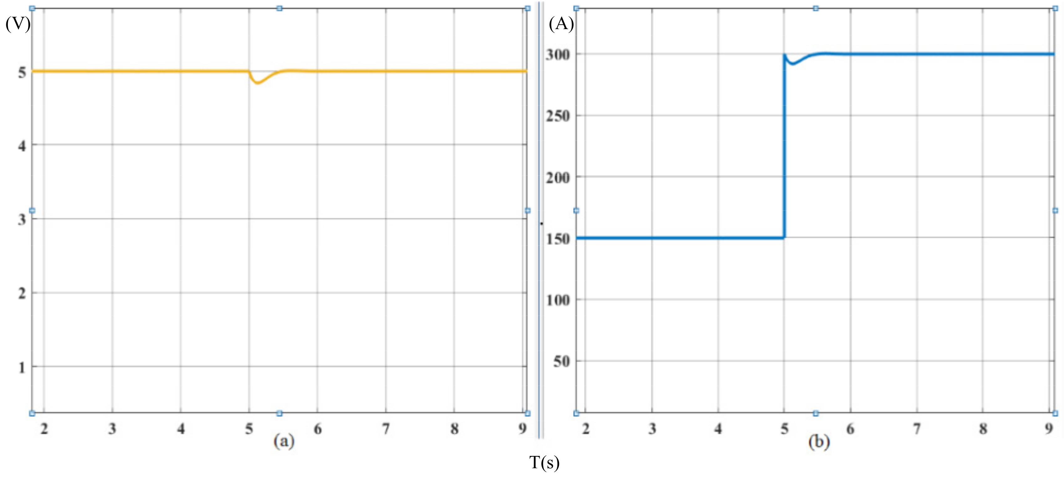
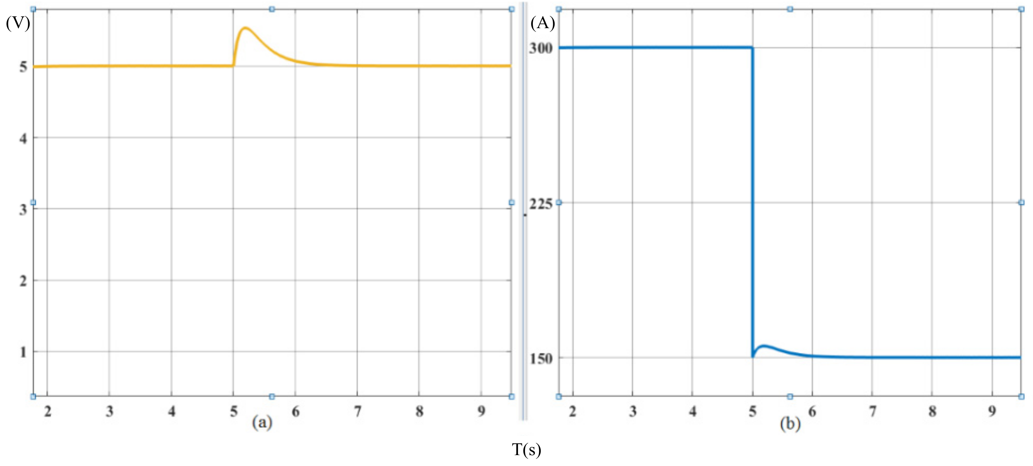
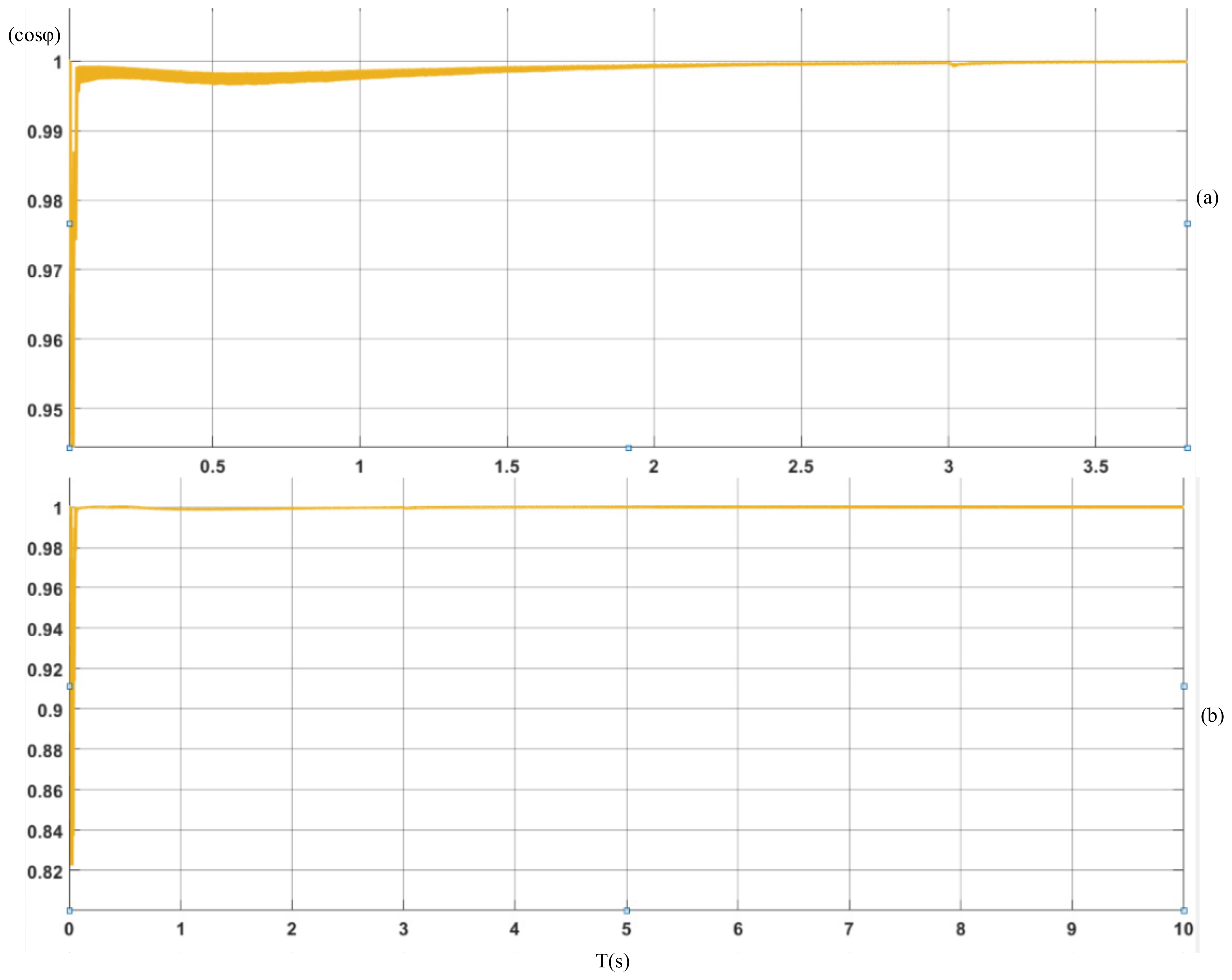
The rectifier system achieves better dynamic and static performance, improves response speed and robustness, and maintains the high power factor operation after load mutation.
The main structure of this paper is as follows, and the second part introduces system structure of a low-voltage and high-current PMSG. The third part shows the nonlinear feed-forward PID control algorithm. The fourth part describes the circuit simulation design of the system based on Simulink. Experimental results are provided in the fifth part, and the sixth part concludes the paper.

2. Methods

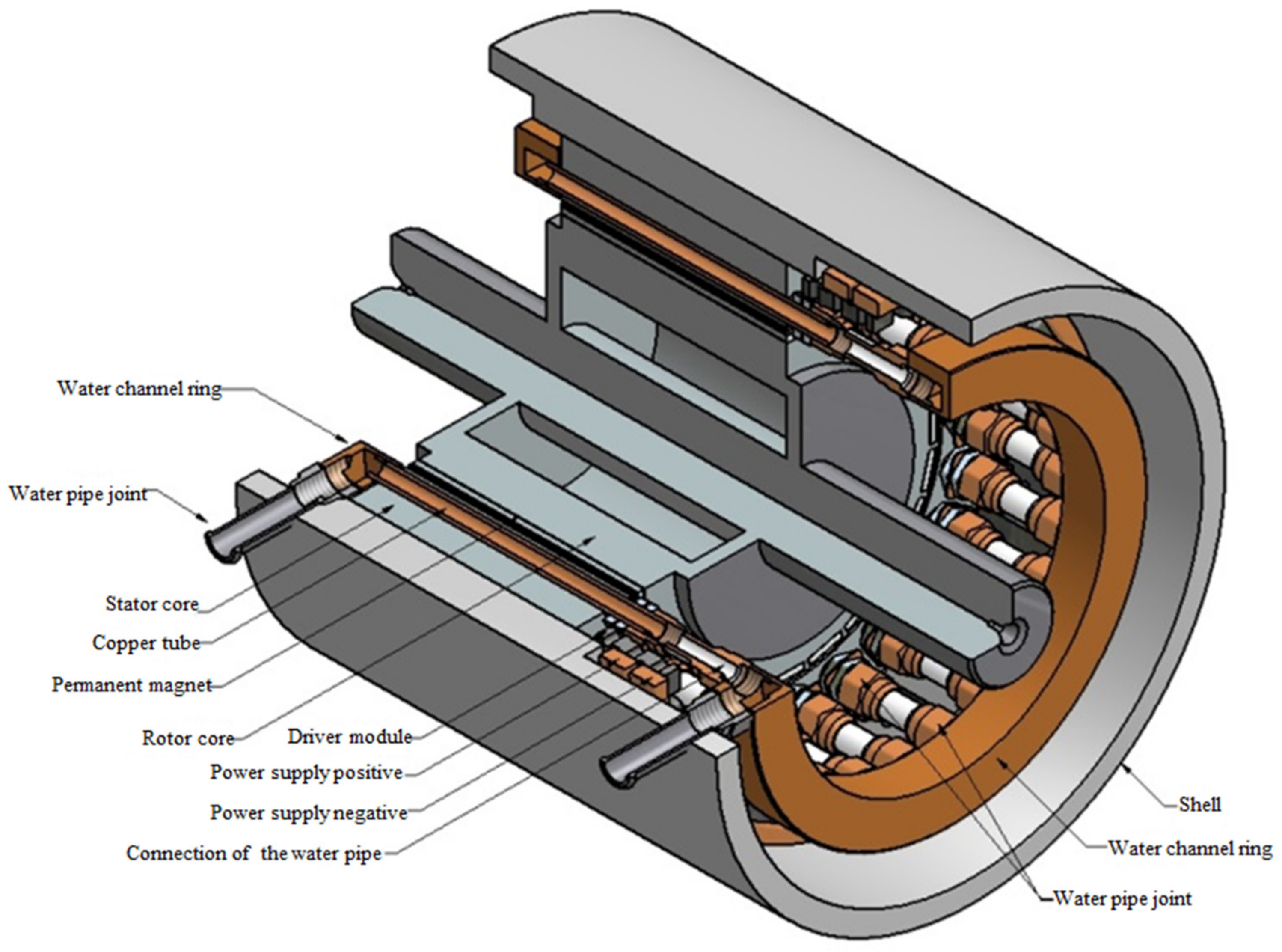
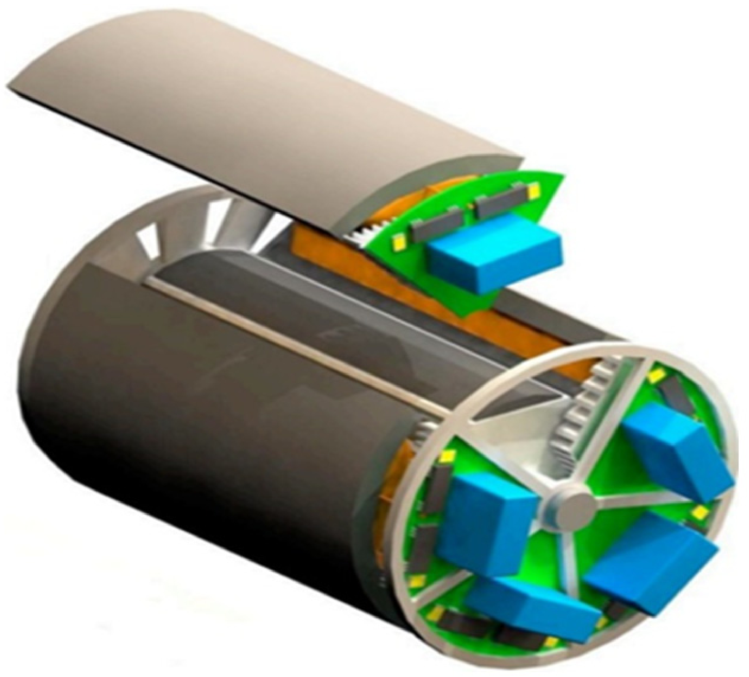
2.1. System Structure of a Low-Voltage and High-Current PMSG

In the fields of shipping, electrolysis and electroplating, the performance index, which is determined by the power density of the generator, has a direct impact on the power performance of the entire system [27]. At present, people continually propose higher requirements for power density of generator. However, in a traditional generator, characteristics of generator structure make the promotion space of power density smaller and smaller [28]. Therefore, this paper, which will start from the aspects of generator structure and driving mode, improves the generator power density and simplifies the generator structure on the premise of keeping the systematic efficiency unchanged. In addition, it is difficult to realize the high-speed operation of the generator at low-voltage for the traditional generator [29]. Therefore, a novel low-voltage and high-current PMSG is proposed in this paper.
The novel PMSG compared with the previous generator has significant differences. The stator of the new type of generator has only a half-turn coil in each slot. The copper tube that serves as a cooling “water channel” is adopted by the coil. Each coil is driven directly and independently. The structure of the stator is shown in Figure 1.
This new type of generator mainly has the following characteristics:
First, there are several coils in the stator slot of a traditional generator. The operational status of the generator is determined by the composite magnetic field of these coils. The magnetic field of the stator with a half-turn coil per slot used in this paper can simulate the composite magnetic field of the multi-winding coil in a traditional generator. As long as the controllable current is provided to the new type of stator winding, normal operation and adjusting speed of the generator can be achieved. In addition, the induced electromotive force of half-turn coil is far less than that of multi-turn coil in a traditional stator structure, which can realize the reliable operation of the generator at low voltage.
Second, the drive unit, which is modularized, is integrated with the generator in the new type of generator. That is, the drive unit of each winding is installed at the end of the generator stator as an independent module. As shown in Figure 2, it can effectively improve the power density of the generator and control system.
Third, the new type of generator studied in this paper can obtain high current at low voltage. When the generator is driven by low voltage, the winding of the armature will inevitably produce large current. However, the high current must rely on a high switching frequency. The development of modern power electronic technology and novel devices can realize the effective drive of this type of generator. The metal oxide semiconductor field effect transistor (MOSFET), which has characteristics of low voltage, high current, high operating frequency and easy parallel connection provides hardware conditions for the realization of direct drive technology of the generator winding.
In addition, the new type of generator has a simple and reliable structure, which makes it adaptable for various application environments. Therefore, this new type of generator is taken as the research object in this paper.

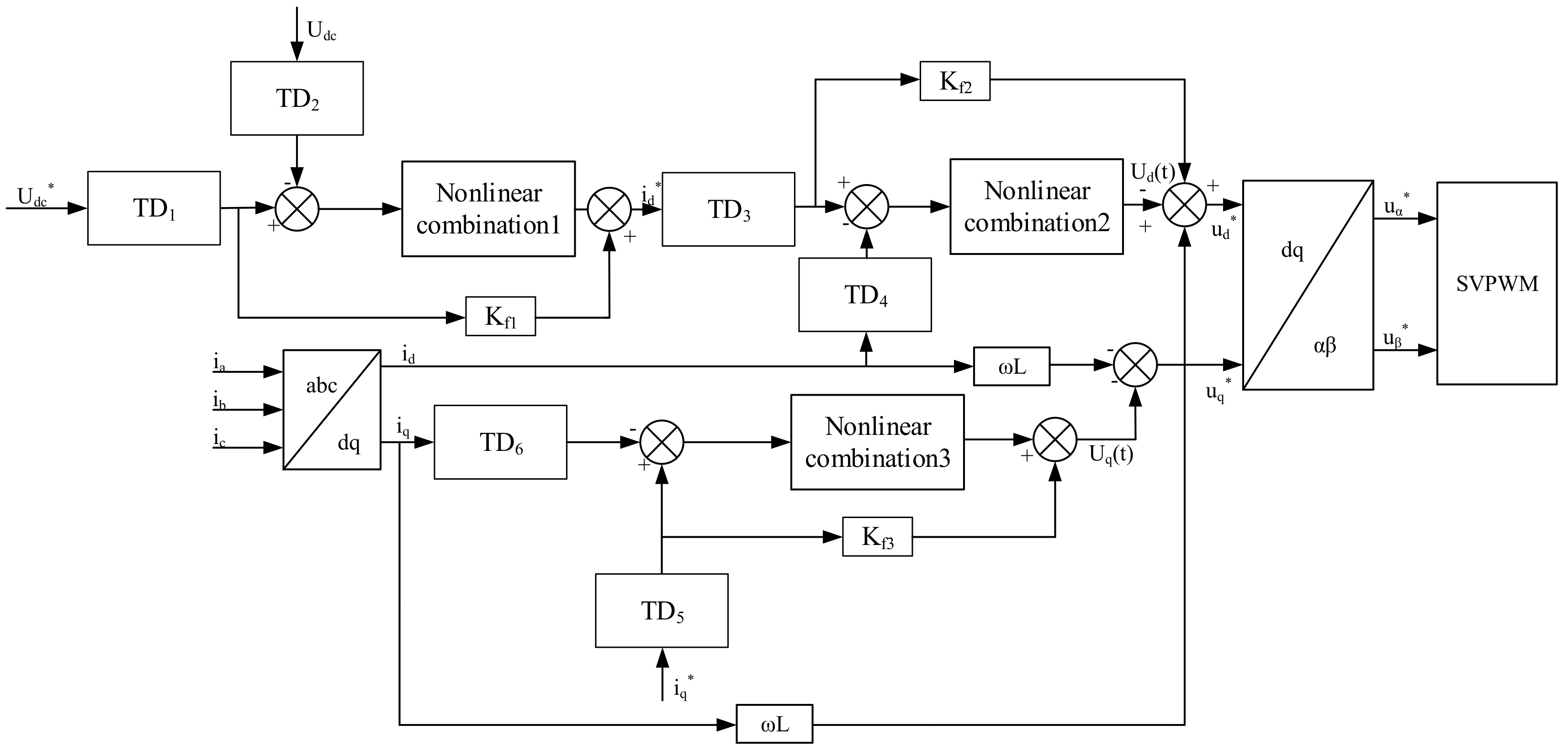
2.2. Nonlinear Feed-Forward PID Control Algorithm

The basic structure of the nonlinear feed-forward PID controller that is used in this paper is shown in Figure 3. The controller consists of the nonlinear PID control and the feed-forward control. Among them, the nonlinear PID control is composed of two tracking differentiators (TD) and a nonlinear combination. The tracking differentiator (I) is utilized to arrange the ideal transition process for the reference input signal v (t) of the system and to extract the differential signal of the reference input signal v (t). The tracking differentiator (II) is utilized to filter the output signal y (t) of the original system and to obtain its differential signal. Based on v1, v2, y1, and y2 obtained by the two tracking differentiators, proportional deviation signal e1 and differential deviation signal e2 are generated, and the integral deviation signal e0 is obtained by deviation signal e1. Based on the three deviation signals, the output of the nonlinear PID controller is formed by using a nonlinear combination. The feed-forward control is constituted by introducing the tracking signal v1 to the control terminal. It is not a closed-loop control, but a classical feed-forward control (2-DOF control). Figure 3 shows a classical 2-DOF controller achieved by different transfer functions from setpoint and process output signal. Therefore, through the combination of feed-forward and feedback, it realizes the purposes of improving robustness and response speed of the system.

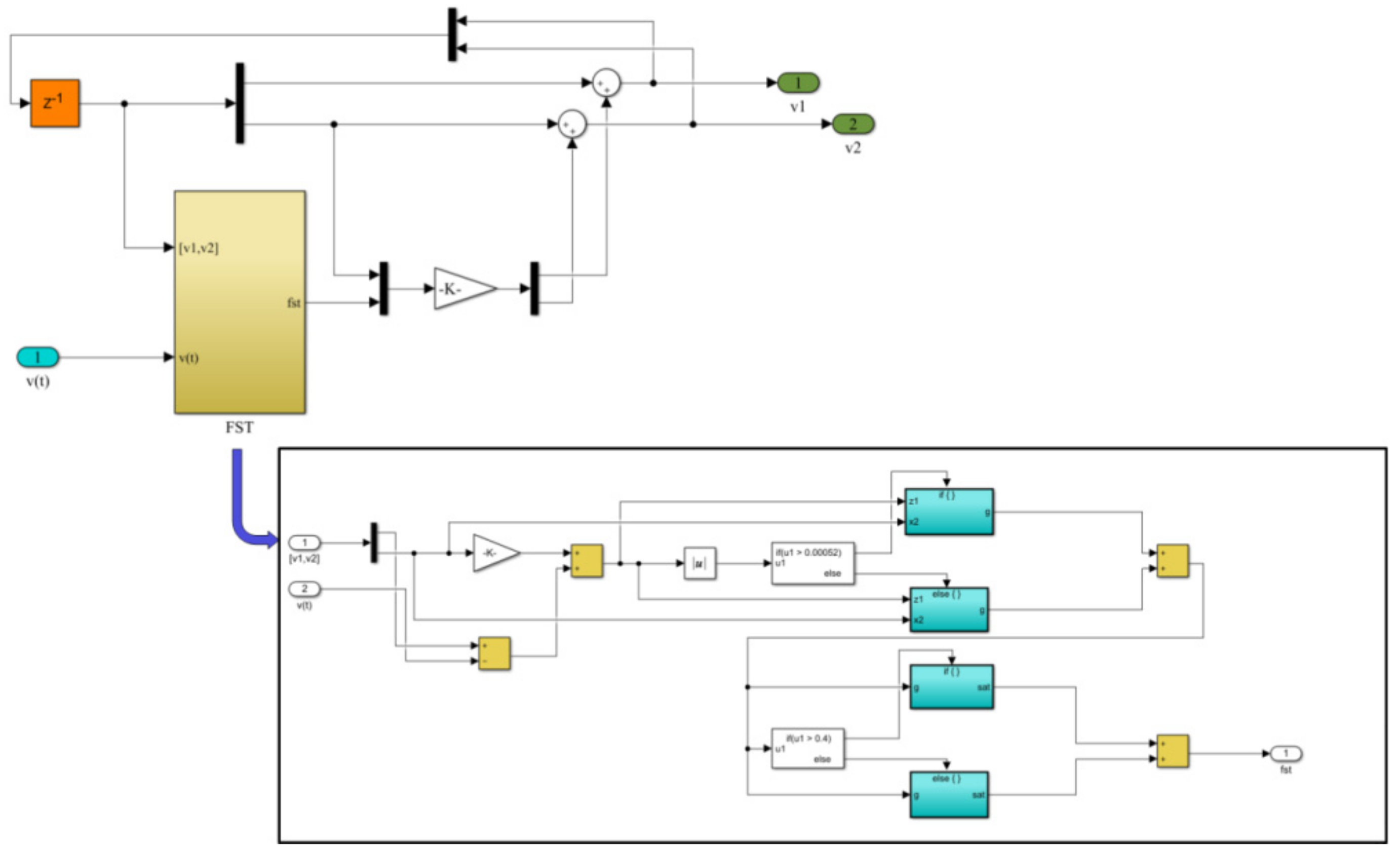
2.2.1. Nonlinear Tracking Differentiator

The so-called nonlinear tracking differentiator is that it will output v1 and v2 if a signal v (t) is inputted to the tracking differentiator. In this situation, v1 tracks v (t), and v2 is taken as the approximate differential of v (t). The simulation results show that when the internal structure of the tracking differentiator is properly constructed, v1 and v2 can extract continuous input signal and differential signal better when the input signal is not continuous or contains noise [30].
In order to design the nonlinear tracking differentiator, a theorem is given.
The system is as the following:
z ˙ 1 = z 2 z ˙ 2 = f ( z 1 , z 2 )
if any solution of the above system will satisfy: z1(t)→0, z2(t)→0(t→∞). Thus, for any bounded integrable function v (t) and any constant T > 0, the system:
x ˙ 1 = x 2 x ˙ 2 = r 2 f [ x 1 v ( t ) , x 2 r ]
solution x1(t) will satisfy as the following:
lim r 0 T x 1 ( t ) v ( t ) d t = 0
where r is the velocity factor and x1 tracks the input signal v (t) at the fastest speed under restricted conditions. When x1 (t) is close enough to v (t), x2 (t) can be taken as an approximate differential of v (t). Formula (2) is a nonlinear tracking differentiator.
In the principle of PID control, if the reference input signal v (t) is discontinuous or non-differentiable, it is taken as a generalized function. The “D” in PID can be approximated by the derivative of smooth function x1 (t) of approximating generalized function v (t), such that the “approximate differential” extracted from the non-differentiable function has a clear meaning.
The above conclusions do not require more specific form of function f (z1, z2) (or f (z1,…,zn)), as long as any solution of system (1) satisfies zi(t)→0(t→∞), i = 1,2,…,n. Thus, we obtain a way of constructing the nonlinear tracking differentiator.
The linear second order system is as the following:
x ˙ 1 = x 2 x ˙ 2 = u , u r
Then, the “fast optimal control” integrated system of Formula (4) is obtained:
x ˙ 1 = x 2 x ˙ 2 = r s g n ( x 1 v ( t ) + x 2 x 2 2 r )
the system has the characteristics of fast convergence and strong anti-interference, thus it is an ideal nonlinear tracking differentiator model. However, the model is easy to produce flutter in practical application. To avoid the fluttering near the origin, an effective second-order nonlinear tracking differentiator is obtained by changing the function sgn (A) to the linear saturation function sat (A, δ). The effective second-order nonlinear tracking differentiator is as the following:
x ˙ 1 = x 2 x ˙ 2 = r s a t ( x 1 v ( t ) + x 2 x 2 2 r , δ )
where the linear saturation function sat (A, δ) is defined as the following:
s a t ( A , δ ) = sgn ( A ) , A > δ A δ , A δ
where δ are a parameter of sat (A, δ).
However, when the nonlinear tracking differentiator is used for numerical calculation, it is easy to produce “high frequency flutter” when system enter the “steady state”, which cannot be avoided by changing sgn (A) to sat (A, δ). Therefore, the discrete form of tracking differentiator is given as the following.
Supposing that the discrete control system:
x 1 ( k + 1 ) = x 1 ( k ) + T x 2 ( k ) x 2 ( k + 1 ) = x 2 ( k ) + T f s t ( x 1 , x 2 )
where fst (x1, x2) is the fastest feedback control system, and it is calculated as follows:
f s t ( x 1 , x 2 ) = r s a t ( g ( Z ) , δ )
where
s a t ( g ( Z ) , δ ) = sgn ( g ( Z ) ) , g ( Z ) > δ g ( Z ) δ , g ( Z ) δ
g ( Z ) = z 2 sgn ( z 1 ) r 2 ( T 8 z 1 r + T 2 ) , z 1 > δ 1 z 2 + z 1 T , z 1 δ 1
z 1 = x 1 + T x 2
z 2 = x 2
δ = r T
δ 1 = δ T
where x1 and x2 are the state variables of the discrete tracking differentiator, and T is the sampling time.
According to the theorem mentioned above, the discrete nonlinear tracking differentiator is constructed as the following.
h = k T
δ = r h
δ 1 = δ h
z 1 = x 1 v ( t ) + h x 2
g = x 2 sgn ( z 1 ) r 2 ( h 8 z 1 r + h 2 ) , z 1 > δ 1 x 2 + z 1 h , z 1 δ 1
s a t ( g , δ ) = sgn ( g ) , g > δ g δ , g δ
where h is the filter factor. The tracking speed is faster, and the accuracy is higher when the value of h is larger. In addition, increasing r can also make tracking speed faster. The fastest feedback control for discrete system is obtained as the following:
f s t ( x 1 , x 2 ) = r s a t ( g , δ )
The output of system is obtained as the following:
x 1 ( k + 1 ) = x 1 ( k ) + T x 2 ( k )
x 2 ( k + 1 ) = x 2 ( k ) + T f s t ( x 1 , x 2 )
where x1 is the tracking input signal and x2 is the differential signal of x1. As previously proven, x2 can be taken as an approximate differential of the input signal. Thus far, the nonlinear tracking differentiator model has been constructed.

2.2.2. Nonlinear Combination

Supposing that the outputs of the two tracking differentiators in Figure 3 are v1, v2 and y1, y2, the three deviation signals are expressed as the following:
e 1 = v 1 y 1 e 2 = v 2 y 2 e 0 = 0 t e 1 d t
According to the three deviation signals obtained in Formula (25), the nonlinear combination is designed as the following:
u ( t ) = K p f a l ( e 1 , α , β ) + K I f a l ( e 0 , α , β ) + K D f a l ( e 2 , α , β )
where KP is the gain coefficient of proportional link controller, KI is the gain coefficient of integral link controller, KD is the gain coefficient of differential link controller, and fal (e, a, β) is the nonlinear function. The specific expression is as the following:
f a l ( e , a , β ) = e β 1 α , e β e α s i g n ( e ) , e > β
where the value of α determines the parameter of the nonlinear degree for fal (e, α, β) and the value of β determines the parameter of the nonlinear interval for fal (e, α, β).
Finally, the output control quantity of nonlinear feed-forward PID controller is as the following:
U ( t ) = K p f a l ( e 1 , α , β ) + K I f a l ( e 0 , α , β ) + K D f a l ( e 2 , α , β ) + K f v 1
where Kf is gain coefficient of the feed-forward link controller.

2.3. Parameter Setting

The nonlinear feed-forward PID controller, which is compared with the traditional controller, must determine more parameters, mainly including: r and h in tracking differentiator and α, β and KP, KI, KD in nonlinear combination, for a total of 7 parameters, where the value of r determines the tracking speed of tracking differentiator, and the value of h determines the ability of suppressing noise. The tracking speed of the tracking differentiator is faster, and the filtering effect is better when the values of r and h are larger. However, the tracking signal will overshoot and vibrate if the values of r and h are too large. The relationship between the bandwidth w and r is given in [23].
w = 1.14 r
The minimum value of r is r0 = w02/1.142. The approximate value of r is determined by simulation analysis after the minimum value of r is determined. Generally speaking, increasing the value of r can effectively accelerate the tracking speed of the tracking differentiator.
The relationship between r and h for the tracking differentiator is given in [24].
r = 0.0001 h 2
At present, there is no effective method to adjust the parameters of the nonlinear combination, which must be adjusted by simulation. However, a large number of simulation calculations show that there are the following rules: in the nonlinear function, the value of α determines the quality of the control quantity, commonly α ∈ (0.5, 1); the value of β, which is generally related to the sampling time, should be appropriately small.
KP, KI, and KD are selected by the trial-and-error method. The design idea of the trial-and-error method is as the following: The KP, KI, and KD are set to certain values based on experience, and disturbances are added to the closed-loop system to observe the output waveform of the transition process. If the waveform is not ideal, the KP, KI, and KD are adjusted repeatedly in the order of proportion, integration and differentiation until satisfactory control quality is obtained.

2.4. Mathematical Model of the Three-Phase Voltage Source PWM Rectifier in the d-q Synchronous Rotating Coordinate System

The state equation of the three-phase voltage source PWM rectifier is described by the unipolar binary logic switching function. When the coordinate transformation of the constant power is conducted, the mathematical models of the three-phase rotating coordinate system can be written as the following:
L d i d d t = v d R i d + ω L i q u d
L d i q d t = v q R i q ω L i q u d
C d u dc d t = i d c i L
where id and iq are the active and reactive current components of the AC input current in the d-q coordinate system; udc is the DC output voltage; idc is the DC output current; iL is the load current; vd and vq are the active and reactive voltage components of the AC input voltage in the d-q dynamic system; C is the DC energy storage capacitance; ud* and uq* are the voltage command values in the control system; ω is the angular velocity of AC current; L is the equivalent inductor in the three-phase PMSG; R is the equivalent resistance in the three-phase PMSG. In order to overcome the influence of nonlinear factors and improve the robustness and adaptability of the system, the nonlinear feed-forward PID control is utilized.
The mathematical model of the double closed-loop control system based on the nonlinear feed-forward PID control can be expressed as the following:
i d = U i ( t ) u d = U d ( t ) + ω L i q + v d u q = U q ( t ) ω L i d
where Ui (t) is the output of the nonlinear feed-forward PID controller about the voltage loop and Ud (t) and Uq (t) are the output of the nonlinear feed-forward PID controller about current loop. Once ud* and uq* is obtained, the pulse can be generated with the space vector pulse width modulation. Figure 4 shows the system diagram of the double closed-loop control.

3. Results and Discussion

For the convenience of the study, a single three-phase rectifier module is selected, which consists of the three-phase AC input voltage section, the rectification and filtering section, the phase locked loop section, and the double closed-loop control section. The simulation model of the three-phase rectifier module is shown in Figure 5. Table 1 shows the simulation parameters of the three-phase rectifier module.
Three phase voltage source PWM rectifier is actually a high-power electronic device whose energy can be transmitted. The PWM rectifier will work in rectification state when the three-phase voltage source PWM rectifier absorbs electric energy from the AC transmission line; the PWM rectifier will work in the inverter state when the three-phase voltage source PWM rectifier feeds back electric energy to the AC transmission line. This paper mainly discusses the rectification state of three-phase voltage source PWM rectifier.
The voltage loop and the current loop of the system are controlled by a nonlinear feed-forward PID controller, respectively, where the nonlinear tracking differentiator (1) is utilized to arrange the ideal transition process for the reference input voltage Udc* of the system and extract the differential signal of the reference input voltage. The tracking differentiator (2) is utilized to filter the DC output voltage Udc of the original system and obtain its differential signal. Based on the signals obtained by the two tracking differentiators, proportional and differential deviation signals e1 and e2 are generated, and the integral deviation signal e0 is obtained by the deviation signal e1. Based on the three deviation signals, the output of the nonlinear PID controller is obtained by using a nonlinear combination. The tracking signal of Udc* is added with the output value of nonlinear PID controller to obtain the output value of nonlinear feed-forward PID controller. Similarly, the nonlinear feed-forward PID control method is applied to the current loop. Finally, the coupling compensation terms ωLid and ωLiq were introduced into the control circuit as feed-forward compensation. The output value of the current loop is added with the feed-forward compensation to obtain the voltage command values ud* and uq* in the control system. The simulation model is shown in Figure 6.
The simulation model of nonlinear tracking differentiator is shown in Figure 7. The nonlinear tracking differentiator is that it will output v1 and v2 if a signal v (t) is input to the tracking differentiator. In this situation, v1 tracks v (t), and v2 is taken as the approximate differential of v (t). This paper determines that the value of r is taken as 60 and the value of h is taken as 0.0013 after the parameter setting and simulation analysis.
The simulation model of nonlinear combination is shown in Figure 8. The nonlinear combination is composed of function fal (e, α, β) that can represent a large range of nonlinear characteristics. The error signal is introduced into the function fal (e, α, β) to obtain the output control quantity of the controller. After the parameter setting and simulation analysis, this paper determines that the value of α is taken as 0.63 and the value of β is taken as 0.4. KP, KI, KD are taken as 200, 500, 150, respectively.
In the phase locked loop of the three-phase rectification system, as shown in Figure 9, the voltage of q axis is controlled to be equal to 0, which is combined with the feedback output voltage to generate an error voltage, and then PI control is used to adjust the voltage without static error. The output of the PI controller is superimposed with the actual input rated frequency to obtain the output frequency, and in turn, the angle and sine values can be obtained.
The SVPWM modulation model is shown in Figure 10.

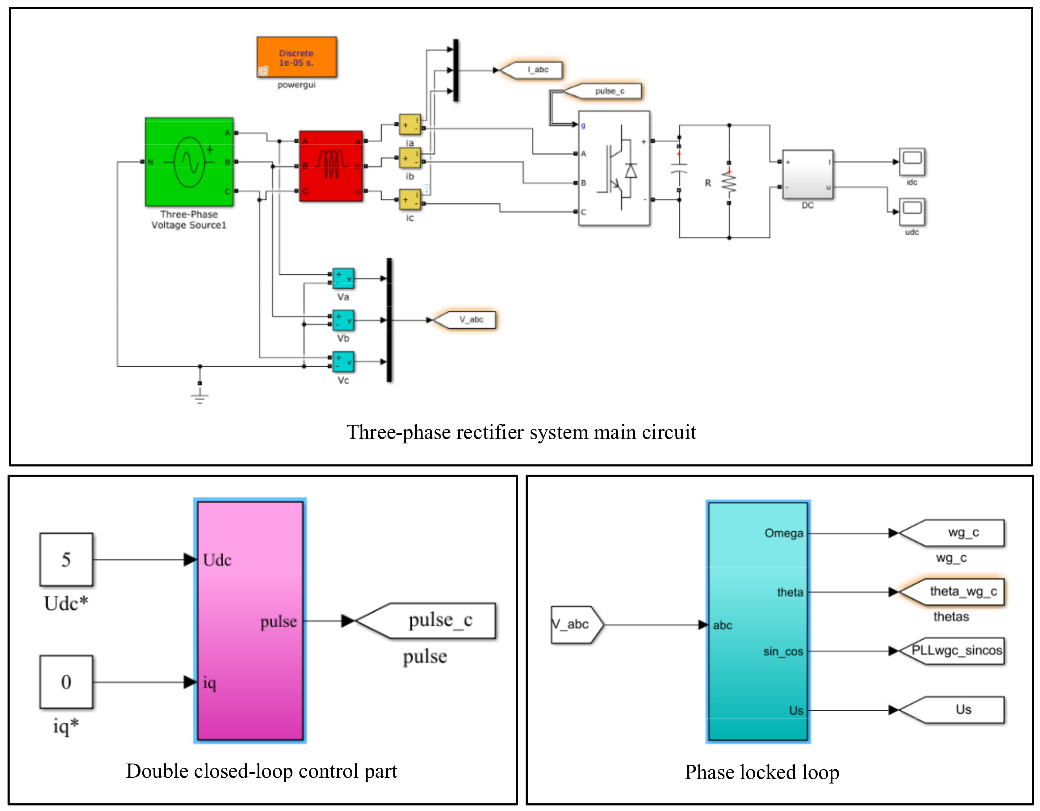
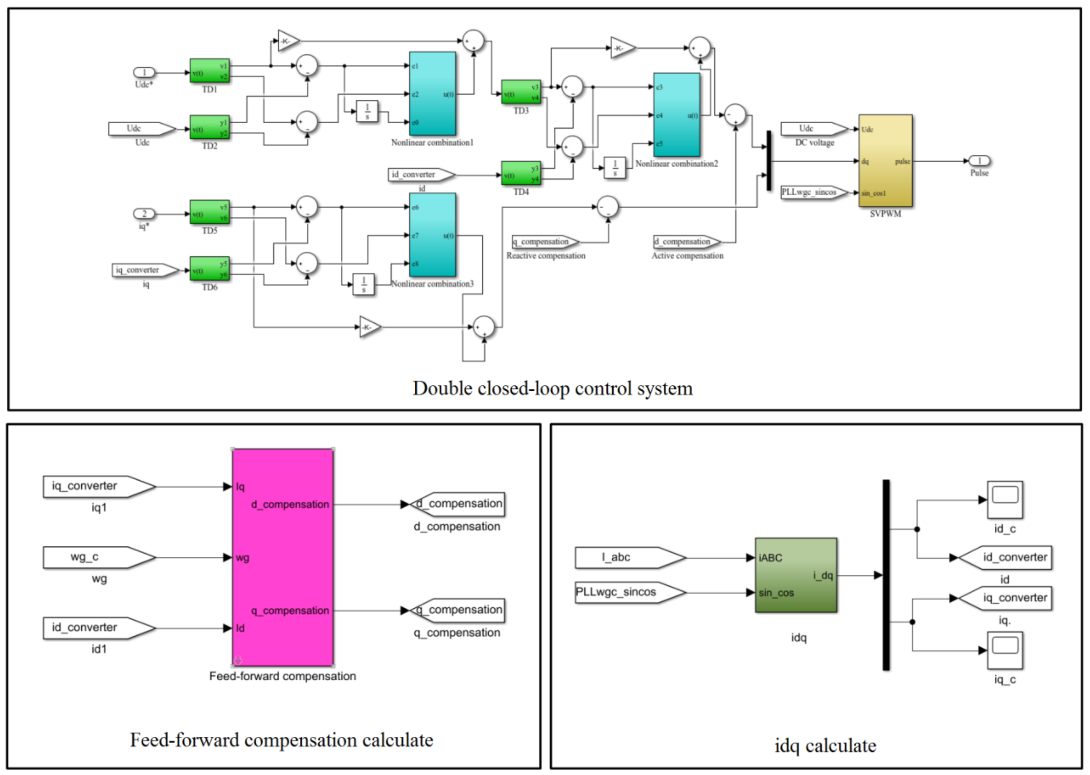
3.1. Simulation Waveforms Comparison and Analysis

In order to verify the efficiency of the proposed control strategy compared to that of conventional methods, the direct power control algorithm [6,7], which are widely used in three-phase PWM rectification systems, were selected in the present study.

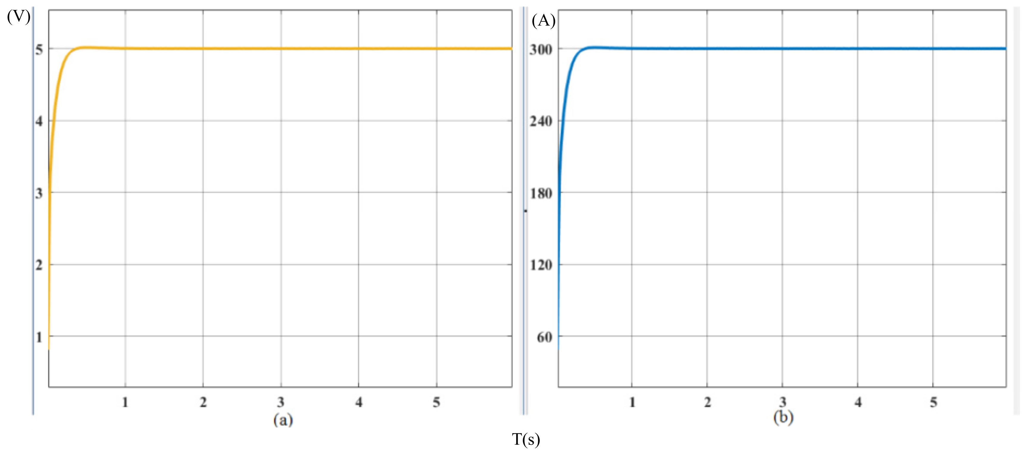
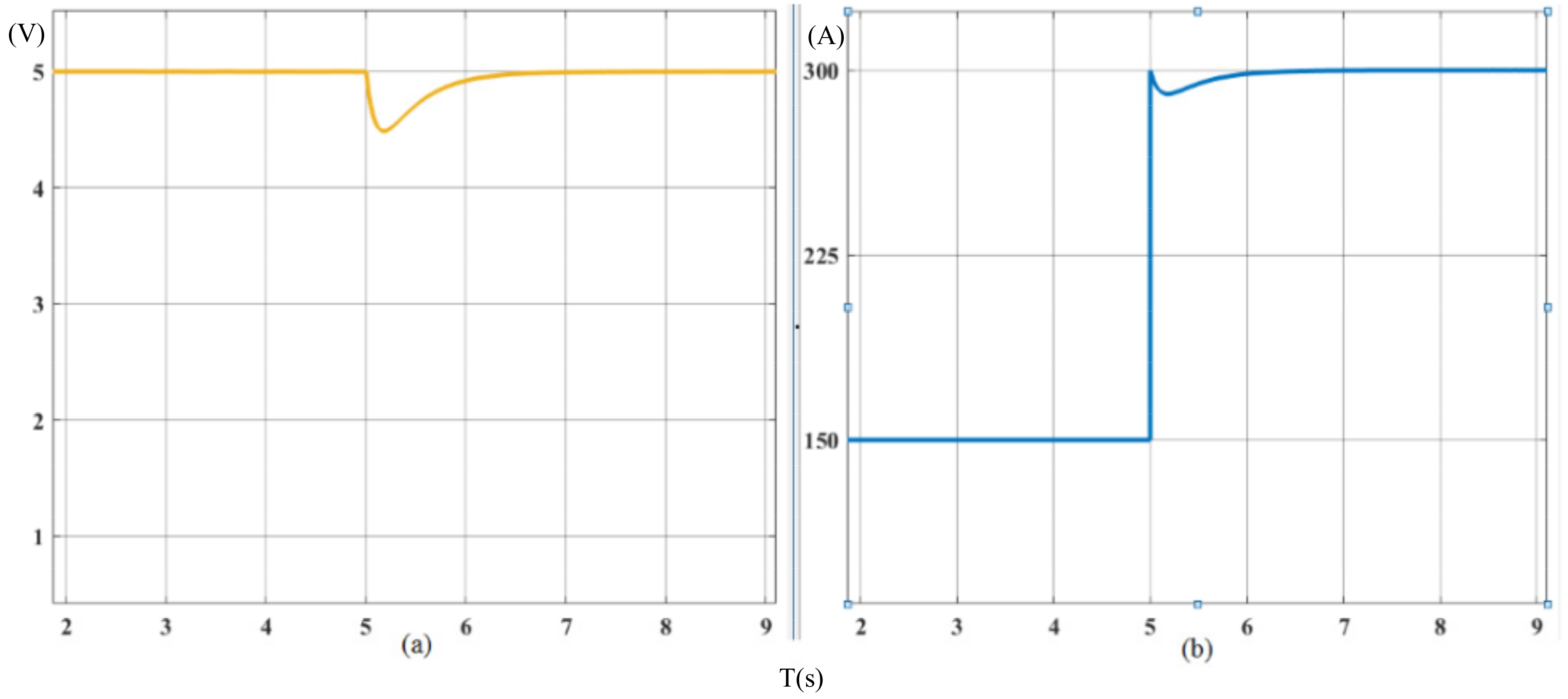
3.1.1. DC Output Waveforms

DC output waveforms, which are controlled by the direct power control method, are shown as the following. Figure 11a indicates that during the power-on process, the system reaches steady state after 2 s and the output voltage is 5 V. Moreover, Figure 11b shows that the output current is 300 A.
DC output waveforms, which are controlled by the nonlinear feed-forward PID control method, are shown as the following. Figure 12a indicates that during the power-on process, the system reaches steady state after 0.3 s and the output voltage is 5 V. Moreover, Figure 12b shows that the output current is 300 A. Compared with the direct power control, the response time was reduced by 1.7 s. The rise of current and voltage is smoother without overshoot.
Figure 13 shows the fast Fourier transform comparison between the direct power control and the nonlinear feed-forward PID control. As a standard sine wave power supply, the synchronous generator contains only odd harmonics. However, the nonlinearity of PWM rectifier components, the dead zone of the control signal, and the lag of the phase-locked loop all lead to the existence of even harmonics, but they are still far lower than the odd harmonics. Controlled by the direct power control, as shown in Figure 13a, the fundamental voltage is 5.2 V and the total harmonic distortion of voltage is 2.7%; controlled by the nonlinear feed-forward PID control, as shown in Figure 13b, the fundamental voltage is 5.02 V and the total harmonic distortion of voltage is 0.17%. It is generated that the nonlinear feed-forward PID control is better than the direct power control method for voltage harmonic suppression.
The load mutation is that the load increases or decreases suddenly at 5 s. Figure 14 shows DC output voltage and current waveforms controlled by the direct power control method when the load suddenly increases at 5 s. The analysis demonstrates that after load increasing, the voltage value returns to stability after reaching about 4.9 V. Meanwhile, the current stabilizes at 300 A, and the entire response process lasts for 1.5 s.
Figure 15 shows DC output waveforms controlled by the nonlinear feed-forward PID control method when the load suddenly increases. It illustrates that the system reaches steady state again after 0.4 s when the load suddenly increases at t = 5 s. The output voltage quickly stabilizes to 5 V and the output current is doubled to 300 A. Compared with the direct power control, the response time is reduced by 1.1 s.
Figure 16 shows DC output voltage and current waveforms controlled by the direct power control method when the load suddenly decreases at t = 5 s. It can be noticed that the DC voltage value starts to approach the steady state value after reaching about 5.1 V, and the current is stable at 150 A. The time of the entire response process is about 1.2 s.
DC output waveforms controlled by the nonlinear feed-forward PID control method when the load suddenly decreases are shown in Figure 17. It can be seen that the system reaches steady state again after 0.4 s, when the load suddenly decreases at t = 5 s. The output voltage is quickly stabilized to 5 V and the output current is halved to 150 A. Compared with the direct power control, the response time is reduced by 0.8 s.

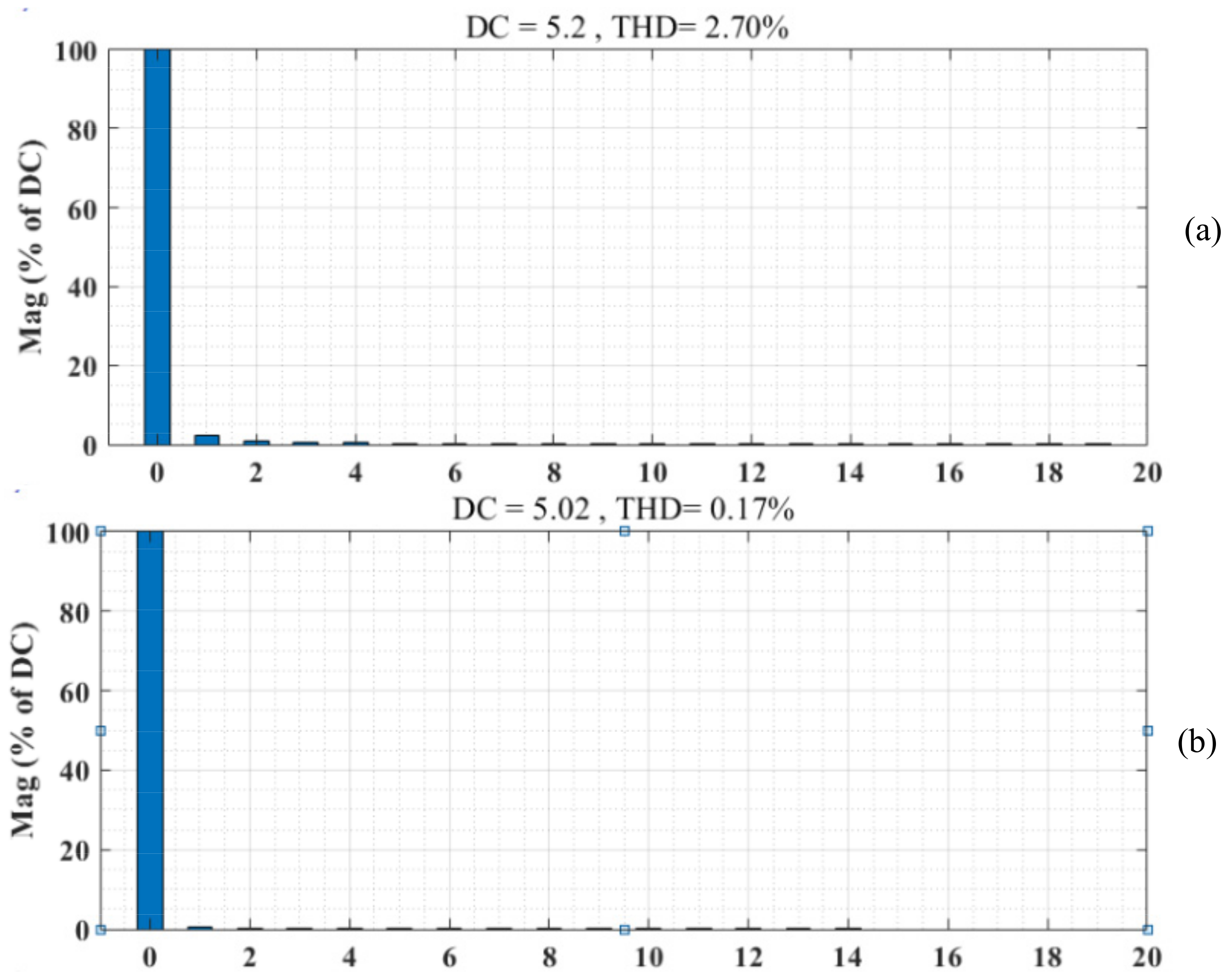
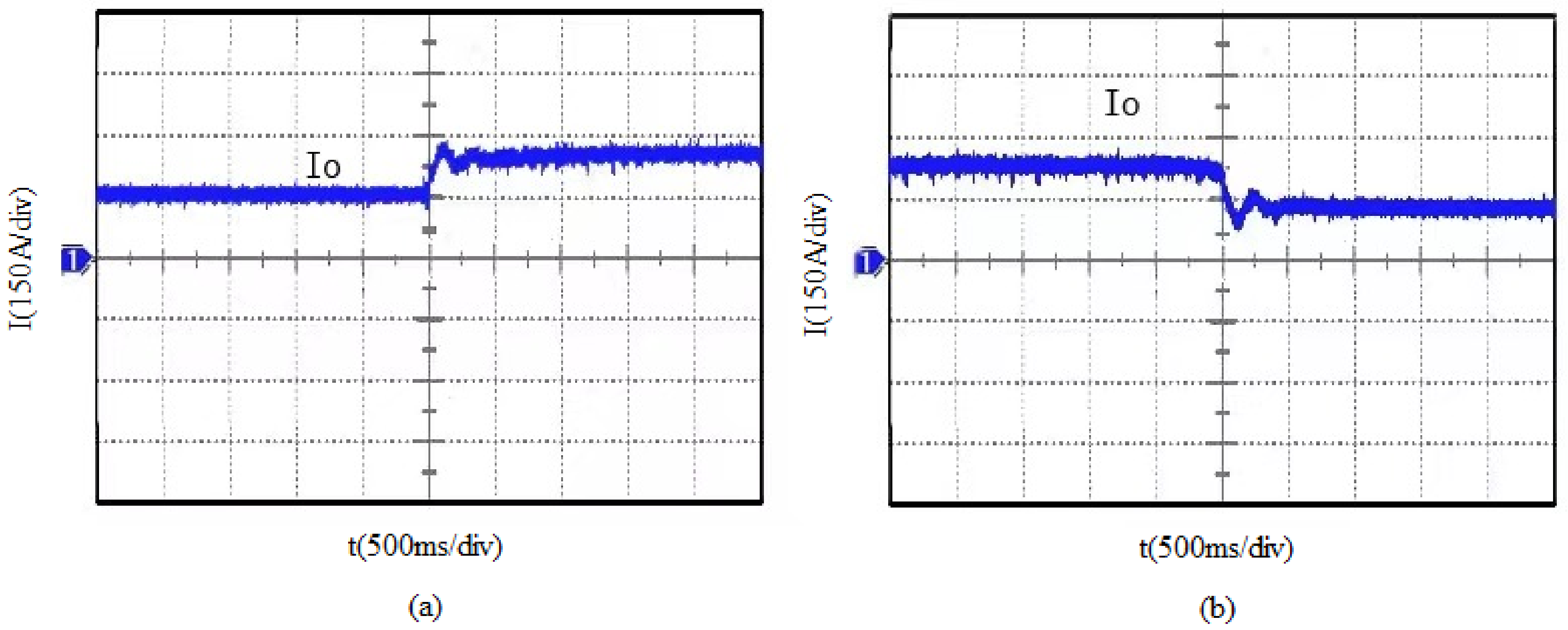
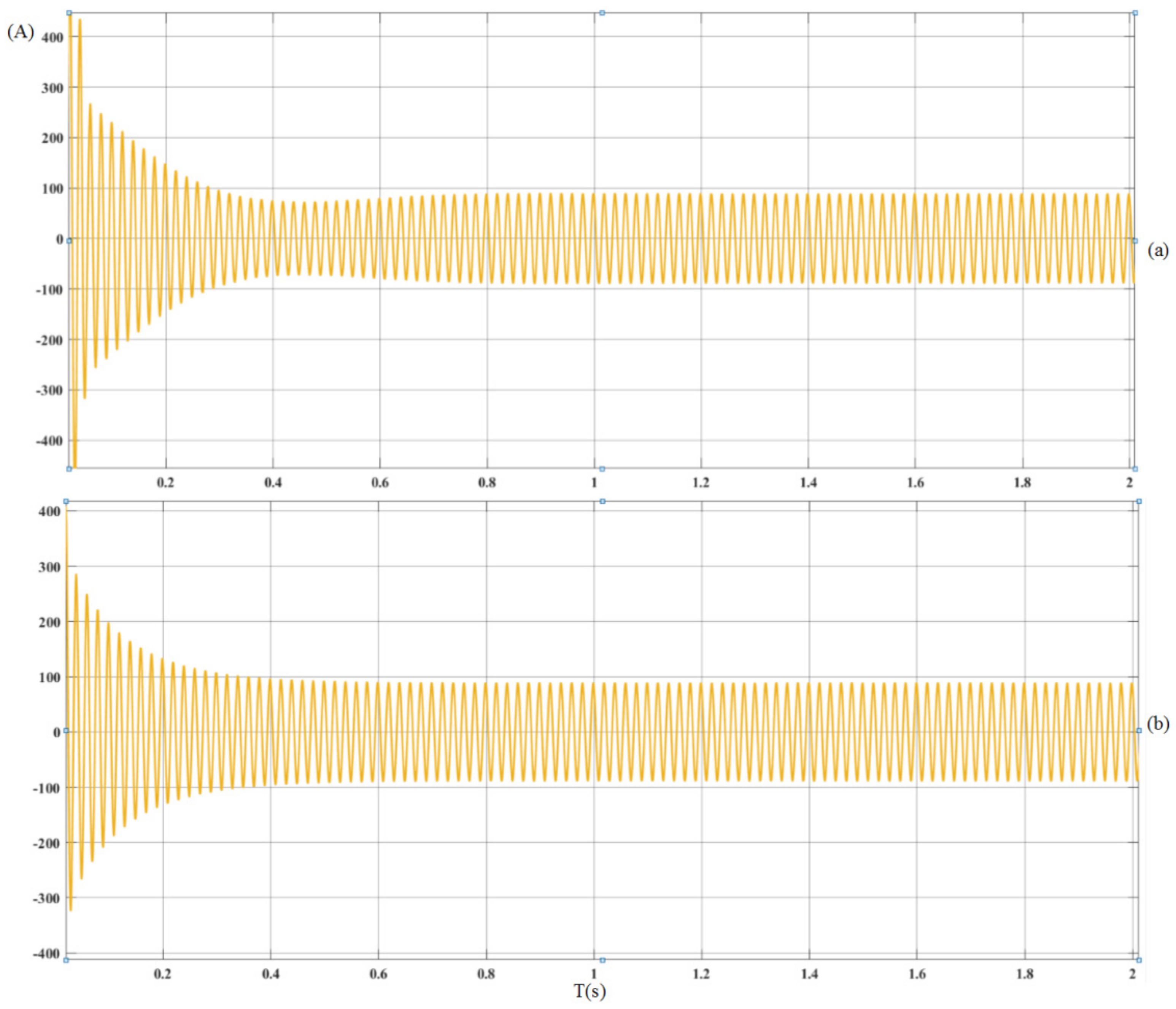
3.1.2. The AC Input Current Waveforms

Based on the simulation model, the AC input current waveforms of the direct power control are compared with that of the nonlinear feed-forward PID control.
Figure 18 shows the comparison of AC input current between the direct power control and the nonlinear feed-forward PID control. From Figure 18a, it can be noticed that A-phase input current, which is controlled by the direct power control method, has the large overshoot, the A-phase current reaches the stable value with the response time of 0.8 s. From Figure 18b, it can be seen that the AC input current soon returns to the new steady state value of 100 A. The current overshoot is obviously reduced, and the entire process time of adjustment is within 0.4 s.
Figure 19 shows the fast Fourier transform of the AC input current comparison between the direct power control and the nonlinear feed-forward PID control. Controlled by the direct power control method, as shown in Figure 19a, the total harmonic distortion of current is 29.41%; controlled by the nonlinear feed-forward PID control, as shown in Figure 19b, the total harmonic distortion of current is 2.86%. It is generated that the nonlinear feed-forward PID control is better than the direct power control method for the AC input current harmonic suppression.
Figure 20 shows the analytical comparison of AC input power factor between the direct power control method and the nonlinear feed-forward PID control. Figure 20a shows AC input power factor, which is controlled by the direct power control method, approaches unit power factor after 2.5 s. Figure 20b shows AC input power factor, which is controlled by the nonlinear feed-forward PID control method, can remain stable at unit power factor at the beginning.
Figure 21 displays the comparison of A-phase input current between the direct power control method and the nonlinear feed-forward PID control after doubling the load. The analysis demonstrates that AC input current value quickly doubles to the stable value. From Figure 21a, it can be noticed that A-phase input current, which is controlled by the direct power control method, has the large overshoot, the A-phase current reaches the stable value with a response time of 0.6 s. After the load mutation, the state point of the system deviates from the switching surface, but the state point tends to move toward the switching surface controlled by the nonlinear feed-forward PID control method. From Figure 21b, it can be seen that AC input current soon returns to the new steady state value of 100 A. The current overshoot is obviously reduced, and the entire process time of adjustment is within 0.3 s.
Figure 22 shows the comparison of A-phase input current between the direct power control method and the nonlinear feed-forward PID control when the load suddenly decreases. From Figure 22a, it can be noticed that the A-phase current reaches the stable value with the response time of 0.6 s. From Figure 22b, it can be seen that AC input current soon returns to the new steady state value, and the entire process time of adjustment is within 0.2 s. The response time is reduced by 0.4 s compared with the direct power control.
According to the above simulation results, it can be seen that the response speed and robustness of the system can be significantly improved by the nonlinear feed-forward PID control. Compared with the direct power control method, the rectification system controlled by the nonlinear feed-forward PID control method has better performance. DC output voltage is more stable, the current distortion is smaller, and AC input current tracks AC input voltage faster in real time. both DC output voltage and AC input current can reach the steady state quickly when the load changes suddenly.

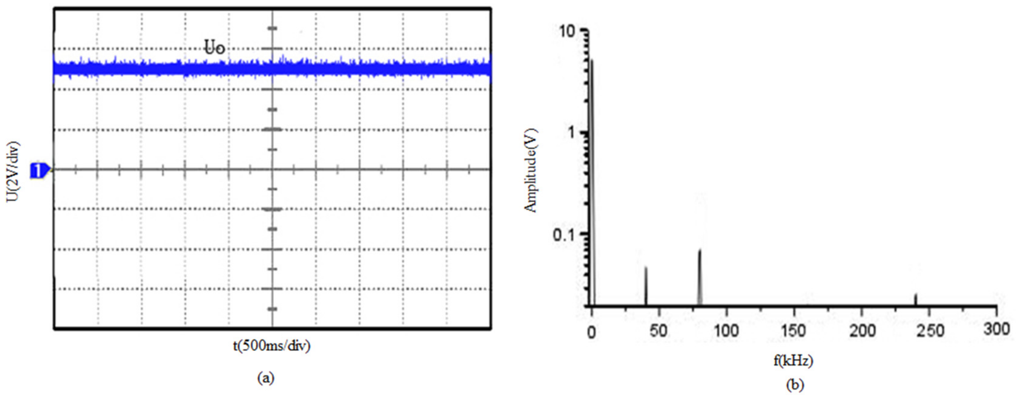
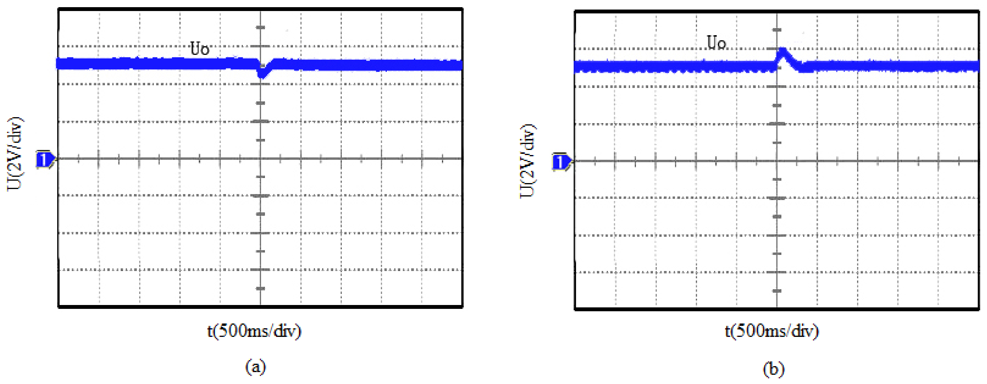
3.2. Verification of the Experimental Result

The development of control algorithms was performed and simulated with Matlab/Simulink and the real-time implementation with a Texas Instrument digital signal processor (DSP) board (TMS320F28335). Each three-phase winding was used as an independent module. Each module, using a 32-bit DSP28335 processor, operated at a frequency of 150 MHz, with a bandwidth of 600 Mbps and a single precision floating-point-unit (FPU). The control strategy can be used in the mainstream 32-bit floating-point microprocessor and 10-bit or more AD sampling. Figure 23 shows the experimental platform, which is the setup for experimental verification. This setup was used to verify the validity of the proposed nonlinear feed-forward PID control algorithm. When conducting a load test, the setup can adjust the resistor box terminal to provide 10–1000 mΩ. The load mutation experiment of the single power module is carried. The experimental principle of other rectifier modules is the same as that of a single rectifier module, which will not be described in detail here. The phase voltage at the AC side of three-phase PMSG is 3.5 V, and the output voltage of the DC side is 5 V.
Figure 24 shows the experimental waveforms of the output voltage and the corresponding frequency spectrum when a single rectifier module is in operation. The logarithmic uniform distribution is used to facilitate the comparison of the longitudinal axis. The diagram shows that the output voltage of the rectifier module is stable. The amplitude of the voltage is 5 V when the main frequency is 0 Hz, and the maximum value of the ripple of each frequency does not exceed 0.06 V, which meets the requirements of the DC output. The experimental results are basically consistent with the dynamic simulation results.
Figure 25 shows the experiment waveforms of the output current and the corresponding spectrum when a single rectifier module is in operation. The vertical axis is logarithmically and uniformly distributed. Moreover, the unit ratio is 100 A. When the main wave of the output current is stable, the main frequency is still 0 Hz, which conforms to DC characteristics. Although there is a certain amplitude in other frequency bands, none of them exceeds 3 A. The experimental results are basically consistent with the simulation results.
Figure 26 shows the waveforms of output voltage when the system load increases and decreases suddenly. The diagram illustrates that when the load changes, the output external characteristics of the rectifier module of the generation system changes under the condition of the same duty cycle. The output voltage in the Figure 26 can quickly return to a stable state in about 0.2 s without overshoot. Only a short fluctuation occurs, and the output voltage remains unchanged at 5 V. The experimental results are basically consistent with the dynamic simulation results. It proves that the dynamic control performance of the nonlinear feed-forward PID control algorithm is superior
Figure 27 shows the waveforms of output current when the system load increases and decreases suddenly. The diagram illustrates that when the load changes, the output external characteristics of the rectifier module changes under the condition of the same duty cycle. The output current in the Figure can quickly return to a stable state in about 0.3 s without overshoot. Only a short fluctuation occurs, and the output current remains unchanged. The experimental results are basically consistent with the dynamic simulation results. It proves that the dynamic control performance of the nonlinear feed-forward PID control algorithm is superior.
As shown in Figure 28, the input current waveform of AC side is shown when the load of system increases or decreases suddenly. It can be seen from the Figure 28 that the input current of sAC side can quickly return to a stable state in about 0.3 s without overshoot. The experimental results are generally consistent with the dynamic simulation results.

4. Conclusions

Aiming the shortcomings of the traditional control methods in a low-voltage and high-current rectifier module, the nonlinear feed-forward PID control method is adopted in this paper. The simulation results demonstrate that the nonlinear feed-forward PID control effectively solves the contradiction between overshoot and rapidity of the system, improves response time while maintaining control accuracy, and has strong adaptability and robustness. The single module is verified by the experimental platform. First, when the system reaches steady state and runs steadily, the output voltage waveform, the output current waveform, and the corresponding frequency spectrum are observed. The output of the system is stable with less harmonic content. Second, verification of the load mutation shows that the system only obtains a tiny fluctuation. The voltage and current at the DC side are not over-regulated. The experimental results are consistent with the simulation results, which prove that the control strategy combining the nonlinear PID control and feed-forward control is an effective and reliable control scheme. Since this experiment, which has periodicity, can cover the entire period, this paper only conducts a single module experiment to achieve a rated output of 5 V/300 A, followed by experiments of three modules in parallel to achieve a stable rated output of 5 V/1000 A.

Author Contributions

Conceptualization, J.L. and J.H.; methodology, J.L. and J.H.; software, J.H.; validation, J.L. and J.H.; formal analysis, J.L. and J.H.; investigation, J.L. and J.H.; writing—original draft preparation, J.L. and J.H.; writing—review and editing, J.L. and J.H.; visualization, H.H.-C.I.; supervision, H.H.-C.I.; project administration, J.L.; funding acquisition, J.L. All authors have read and agreed to the published version of the manuscript.

Funding

This research was funded by Natural Science Foundation of Heilongjiang Province, grant number LH2019E067.

Conflicts of Interest

The authors declare no conflict of interest.

References

  1. Shen, J.; Xin, B.; Cui, H.; Gao, W. Control of Single-Axis Rotation INS by Tracking Differentiator Based Fuzzy PID. IEEE Trans. Aerosp. Electron. Syst. 2017, 53, 2976–2986. [Google Scholar] [CrossRef]
  2. Zhang, J.; Guo, L. Theory and Design of PID Controller for Nonlinear Uncertain Systems. IEEE Control Syst. Lett. 2019, 3, 643–648. [Google Scholar] [CrossRef]
  3. Ge, J.; Zhao, Z.; Yuan, L.; Lü, T.; He, F. Direct Power Control Based on Natural Switching Surface for Three-Phase PWM Rectifiers. IEEE Trans. Power Electron. 2015, 30, 2918–2922. [Google Scholar] [CrossRef]
  4. Bouafia, A.; Krim, F.; Gaubert, J.-P. Fuzzy-Logic-Based Switching State Selection for Direct Power Control of Three-Phase PWM Rectifier. IEEE Trans. Ind. Electron. 2009, 56, 1984–1992. [Google Scholar] [CrossRef]
  5. Malinowski, M.; Kázmierkowski, M.; Hansen, S.; Blaabjerg, F.; Marques, G. Virtual-flux-based direct power control of three-phase PWM rectifiers. IEEE Trans. Ind. Appl. 2001, 37, 1019–1027. [Google Scholar] [CrossRef]
  6. Vazquez, S.; Sanchez, J.; Carrasco, J.; Leon, J.I.; Galvan, E. A Model-Based Direct Power Control for Three-Phase Power Converters. IEEE Trans. Ind. Electron. 2008, 55, 1647–1657. [Google Scholar] [CrossRef]
  7. Wang, J.H.; Li, H.D.; Wang, L.M. Direct power control system of three phase boost type PWM rectifiers. Proc. CSEE 2006, 26, 54–60. [Google Scholar]
  8. Zhang, Q.Q.; Zhao, Z.X.; Gu, S.H. The PWM rectifier with LCL filter direct power control based on power damping feedback. J. Vibroen Gineering 2021, 23, 51–55. [Google Scholar]
  9. Wang, X.D.; Liu, X.; Mo, Z.H.; Wen, J.; Xiong, Z.H. Novel model predictive direct power control strategy for grid-connected three-level NPC inverters. IET Power Electron. 2020, 13, 16–17. [Google Scholar] [CrossRef]
  10. Logenthiran, T.; Naayagi, R.T.; Woo, W.L.; Phan, V.; Abidi, K. Intelligent Control System for Microgrids Using Multiagent System. IEEE J. Emerg. Sel. Top. Power Electron. 2015, 3, 1036–1045. [Google Scholar] [CrossRef]
  11. Cai, S.M.; Wang, Y.G.; Tian, T. Intelligent PID control algorithm research and Matlab implementation. Electron. Sci. Technol. 2016, 29, 43–46. [Google Scholar]
  12. Huang, M.G. Application of nonlinear PID control in intelligent control of double propeller and double rudder ships. Ship Sci. Technol. 2020, 42, 25–27. [Google Scholar]
  13. Zhao, L. Application of high voltage permanent magnet motor and remote frequency conversion intelligent control system. Mech. Manag. Dev. 2020, 35, 172–174. [Google Scholar]
  14. Liu, L.H. Research on PID control method based on intelligent control. J. Beijing Inst. Technol. 2012, 11, 33–38. [Google Scholar]
  15. Guan, H.M. Application of intelligent control algorithm in motor control. Inf. Rec. Mater. 2019, 20, 85–86. [Google Scholar]
  16. Tian, J.; Yang, L.; Xue, R. PWM speed regulation of DC motor based on intelligent control. Value Eng. 2019, 38, 142–144. [Google Scholar]
  17. Jung, J.; Leu, V.Q.; Do, T.D.; Kim, E.; Choi, H.H. Adaptive PID Speed Control Design for Permanent Magnet Synchronous Motor Drives. IEEE Trans. Power Electron. 2015, 30, 900–908. [Google Scholar] [CrossRef]
  18. Zhou, Y.; Zeng, Z.Z. Research on the principle of self-learning nonlinear PID disturbance rejection control. Control Eng. 2017, 24, 1180–1185. [Google Scholar]
  19. Wang, R.T.; Zeng, Y.Z.; Su, X.K. Research on single phase PWM rectifier based on nonlinear PID control theory. Electr. Meas. Instrum. 2017, 54, 113–116. [Google Scholar]
  20. Lei, Z.; Zhou, Y. A kind of nonlinear PID controller for Refrigeration Systems based on Vapour Compression. IFAC PapersOnLine 2018, 51, 716–721. [Google Scholar] [CrossRef]
  21. So, G.B.; Jin, G.G. Fuzzy-based nonlinear PID controller and its application to CSTR. Korean J. Chem. Eng. 2018, 35, 819–825. [Google Scholar] [CrossRef]
  22. Yan, H.L.; Li, J.P.; Li, L.M. Design of active disturbance rejection controller for PMSG servo system. J. Terahertz Sci. Electron. Inf. 2021, 19, 138. [Google Scholar]
  23. Shi, Y.L.; Hou, C.Z. Design of improved nonlinear tracking differentiator. Control. Decis. 2008, 23, 647–650. [Google Scholar]
  24. Han, J.Q.; Wang, W. Nonlinear tracking differentiator. Syst. Sci. Math. 1994, 14, 177–183. [Google Scholar]
  25. Liu, Y.B.; Jia, Q.; Zhang, F.; Zhang, X.H.; Zhang, J.Z. Research and Simulation of There-phase Vienna Rectifier Based on Feedforward Decoupling Control. J. Phys. Conf. Ser. 2021, 1885, 35–37. [Google Scholar] [CrossRef]
  26. Wu, H. A Feedforward Decoupling Control Method for Multi-ports DC Transformer. J. Phys. Conf. Ser. 2021, 1732, 255–259. [Google Scholar]
  27. Ma, R.B.; Lin, Y. Selection of driving motor for pure electric passenger car. Automot. Eng. 2010, 24, 46–48. [Google Scholar]
  28. Fan, Z.C.; Yu, Q.G.; Zhang, X.M. Double stator winding synchronous motor and its single winding equivalent model. J. Electrotech. 2007, 22, 2–8. [Google Scholar]
  29. Wang, Q.; Zhang, J.; Ruan, X.B. Isolated Single Primary Winding Multiple-Input Converters. IEEE Trans. Power Electron. 2011, 26, 3435–3442. [Google Scholar] [CrossRef]
  30. Liu, Z.G. Design of improved tracking differentiator. Navig. Control. 2018, 17, 61–65. [Google Scholar]
Figure 1. The stator structure of the new type of generator.
Electronics 10 02138 g001
Figure 2. Integrated structure of generator and driver.
Electronics 10 02138 g002
Figure 3. Structure diagram of the nonlinear feed-forward PID control.
Electronics 10 02138 g003
Figure 4. System diagram of the double closed-loop control.
Electronics 10 02138 g004
Figure 5. Simulation model of rectifier module.
Electronics 10 02138 g005
Figure 6. Simulation model of double closed-loop control system based on nonlinear feed-forward PID control.
Electronics 10 02138 g006
Figure 7. Simulation model of nonlinear tracking differentiator.
Electronics 10 02138 g007
Figure 8. Simulation model of nonlinear combination.
Electronics 10 02138 g008
Figure 9. Simulation model of phase locked loop.
Electronics 10 02138 g009
Figure 10. Simulation model of SVPWM modulation.
Electronics 10 02138 g010
Figure 11. DC output waveforms controlled by the direct power control method: (a) voltage waveform; (b) current waveform.
Electronics 10 02138 g011
Figure 12. DC output waveforms controlled by the nonlinear feed-forward PID control method: (a) voltage waveform; (b) current waveform.
Electronics 10 02138 g012
Figure 13. Fast Fourier transform analysis of DC output voltage: (a) controlled by the direct power control method; (b) controlled by the nonlinear feed-forward PID control method.
Electronics 10 02138 g013
Figure 14. DC output waveforms controlled by the direct power control method when the load suddenly increases: (a) voltage waveform; (b) current waveform.
Electronics 10 02138 g014
Figure 15. DC output waveforms controlled by the nonlinear feed-forward PID control when the load suddenly increases: (a) voltage waveform; (b) current waveform.
Electronics 10 02138 g015
Figure 16. DC output waveforms controlled by the direct power control method when the load suddenly decreases: (a) voltage waveform; (b) current waveform.
Electronics 10 02138 g016
Figure 17. DC output waveforms controlled by the nonlinear feed-forward PID control method when the load suddenly decreases: (a) voltage waveform; (b) current waveform.
Electronics 10 02138 g017
Figure 18. Startup response of AC input current waveform: (a) controlled by the direct power control method; (b) controlled by the nonlinear feed-forward PID control method.
Electronics 10 02138 g018
Figure 19. Fast Fourier transform analysis of AC input current: (a) controlled by the direct power control method; (b) controlled by the nonlinear feed-forward PID control method.
Electronics 10 02138 g019
Figure 20. Power factor of AC input side: (a) controlled by the direct power control method; (b) controlled by the nonlinear feed-forward PID control method.
Electronics 10 02138 g020
Figure 21. A-phase current waveforms when the load suddenly increases: (a) controlled by the direct power control method; (b) controlled by the nonlinear feed-forward PID control method.
Electronics 10 02138 g021
Figure 22. A-phase current waveforms when the load suddenly decreases: (a) controlled by the direct power control method; (b) controlled by the nonlinear feed-forward PID control method.
Electronics 10 02138 g022
Figure 23. Large current load experiment of the integrated DC output system: (a) experimental platform; (b) load experiment.
Electronics 10 02138 g023
Figure 24. Experimental voltage waveforms of the DC power generation: (a) output voltage waveform; (b) output voltage spectrum.
Electronics 10 02138 g024
Figure 25. The experimental current waveforms of DC power generation: (a) output current waveform; (b) output current spectrum.
Electronics 10 02138 g025
Figure 26. Output voltage waveforms of load mutation: (a) load increases; (b) load decreases.
Electronics 10 02138 g026
Figure 27. Output current waveforms of load mutation: (a) load increases; (b) load decreases.
Electronics 10 02138 g027
Figure 28. Input current waveforms of load mutation: (a) load increases; (b) load decreases.
Electronics 10 02138 g028
Table 1. Simulation circuit parameters.
ParameterValue
Three-phase input line voltage, e4.2 V
Three-phase input voltage frequency, f50 Hz
Switching frequency, f20 kHz
DC-bus capacitor, C2200 μF
DC-bus voltage, udc5 V
AC-bus equivalent inductance, L1.5 mH
Load resistance, RL32 Ω
Publisher’s Note: MDPI stays neutral with regard to jurisdictional claims in published maps and institutional affiliations.

