
Improved Active Disturbance Rejection Control of Dual-Axis Servo Tracking Turntable with Friction Observer


Abstract
:1. Introduction
2. Dynamic Model of Dual-Axis Servo Tracking Turntable System
2.1. Mechanism Modelling of Servo Turntable
2.2. Nonlinear Friction Modelling
3. Design of Improved Active Disturbance Rejection Controller
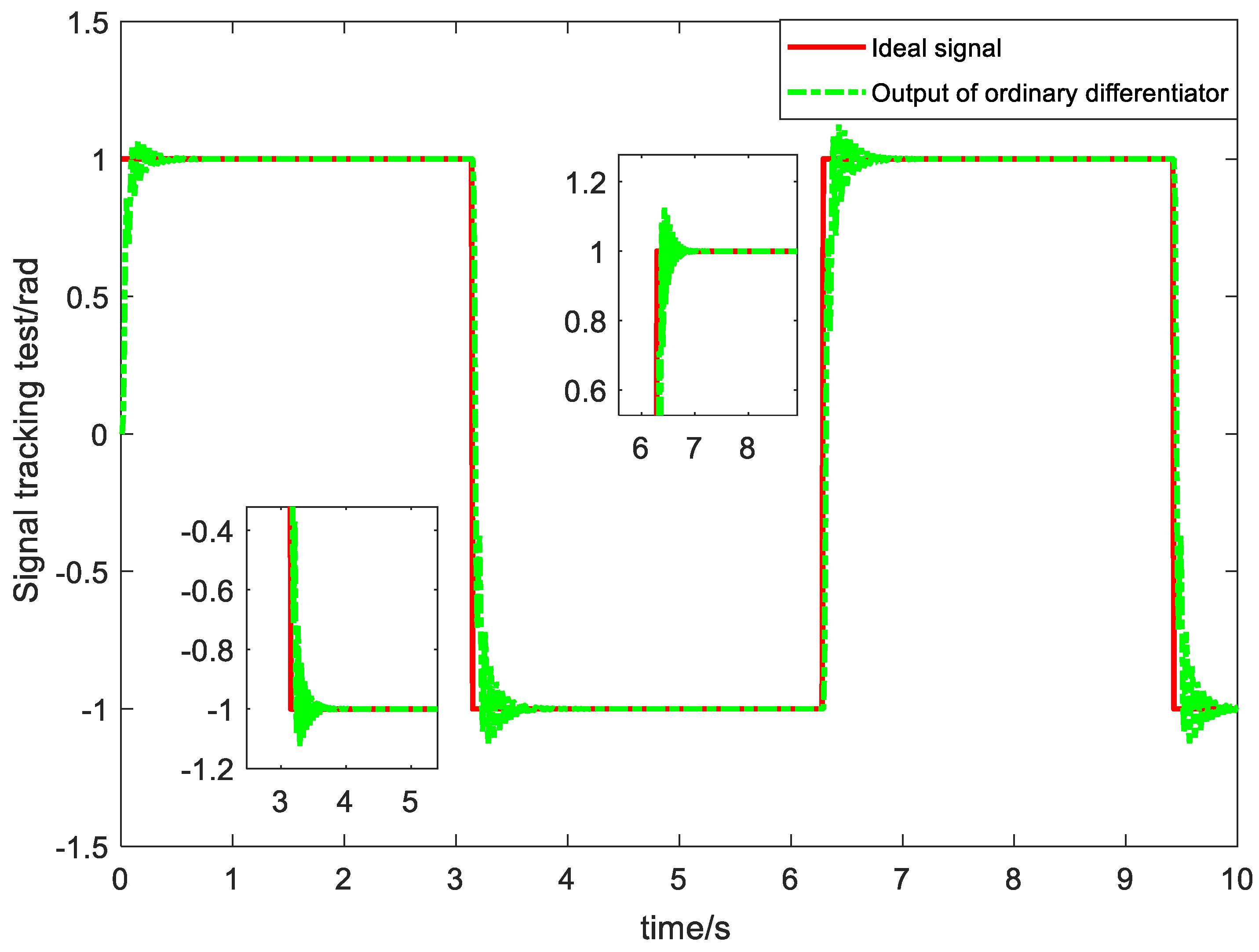
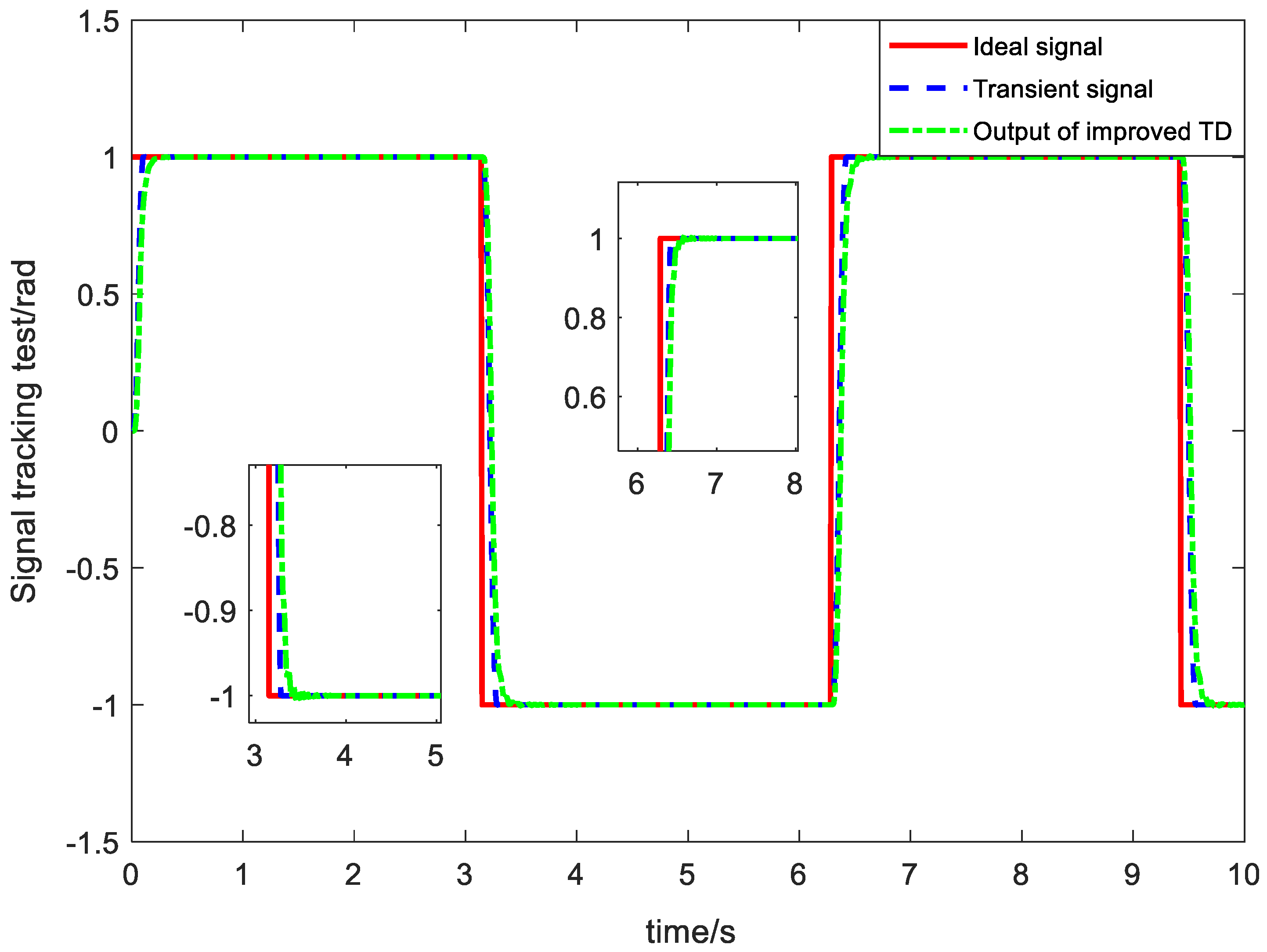
3.1. Improved Tracking Differentiator
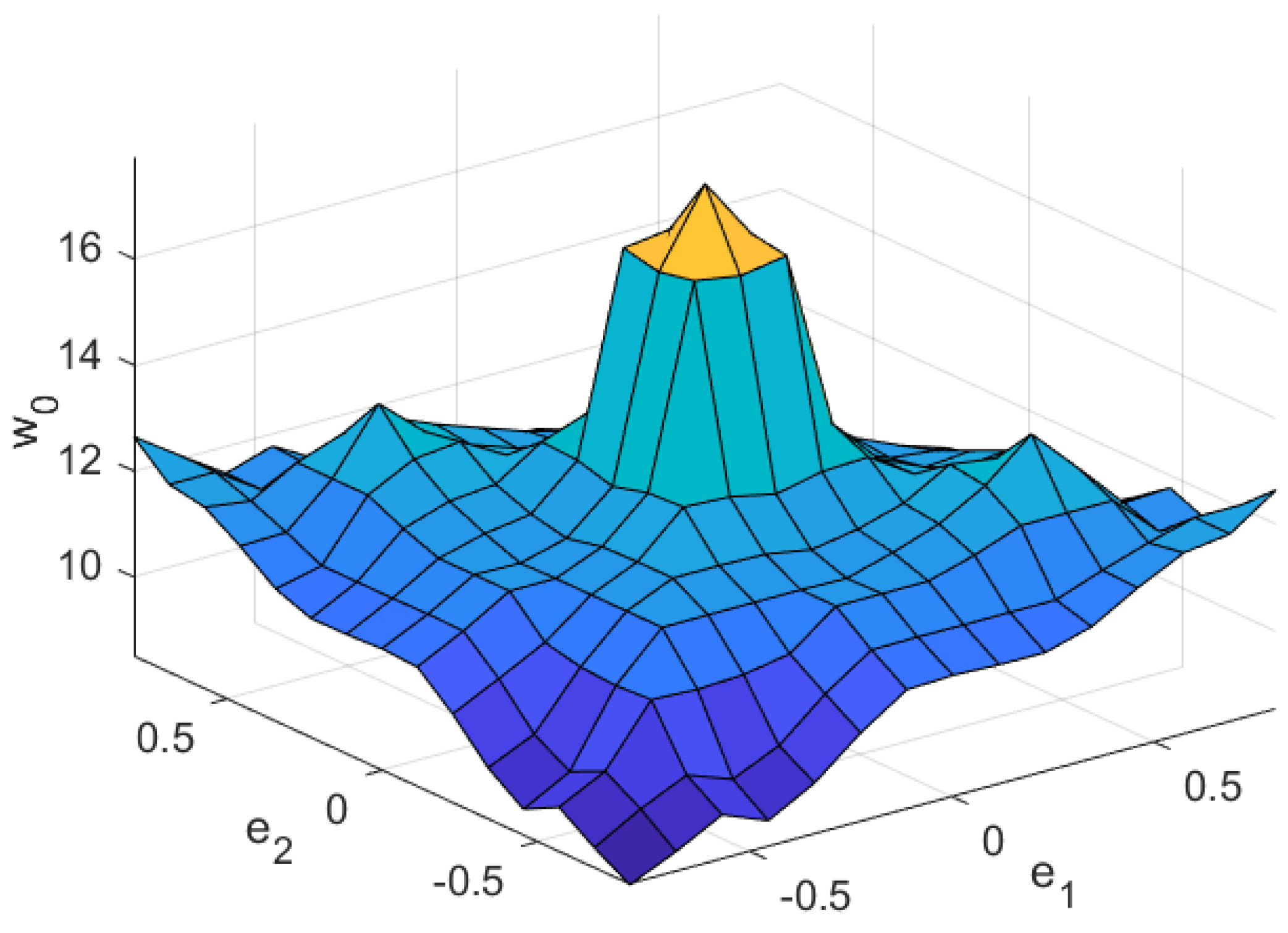
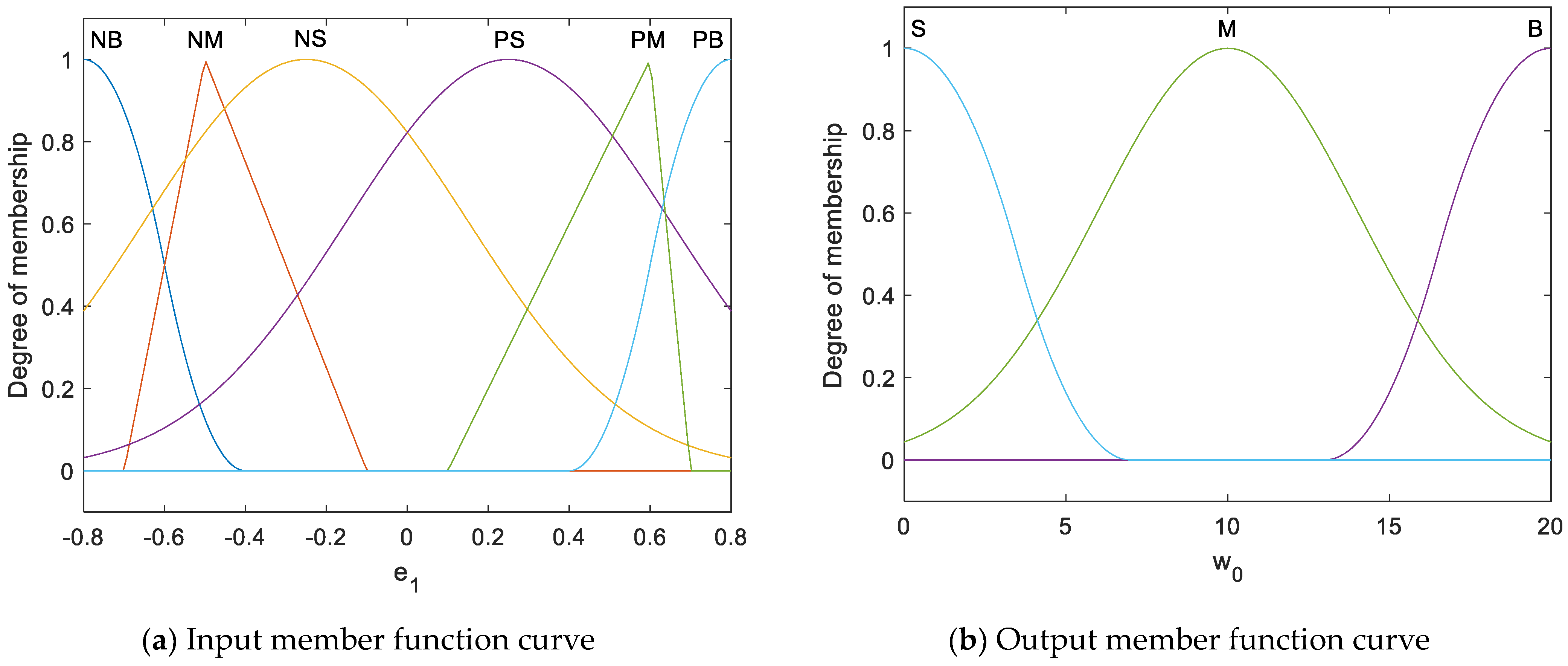
3.2. Improved Extended State Observer
- Rule 1: If is NB, then is S.
- Rule 2: If is NM, then is M.
- Rule 3: If is NS, then is B.
- Rule 4: If is PS, then is B.
- Rule 5: If is PM, then is M.
- Rule 6: If is PB, then is S.
3.3. State Error Feedback Control Law
4. Stability Analysis
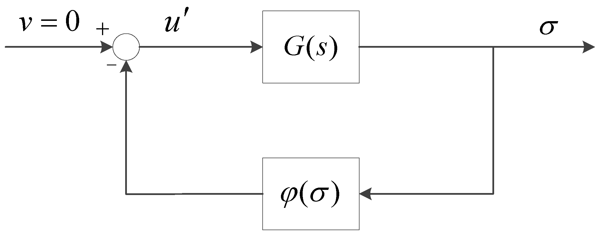
4.1. System Transformation
4.2. Extended Circle Criteria
4.3. Stability Analysis Based on the Extended Circle Criteria
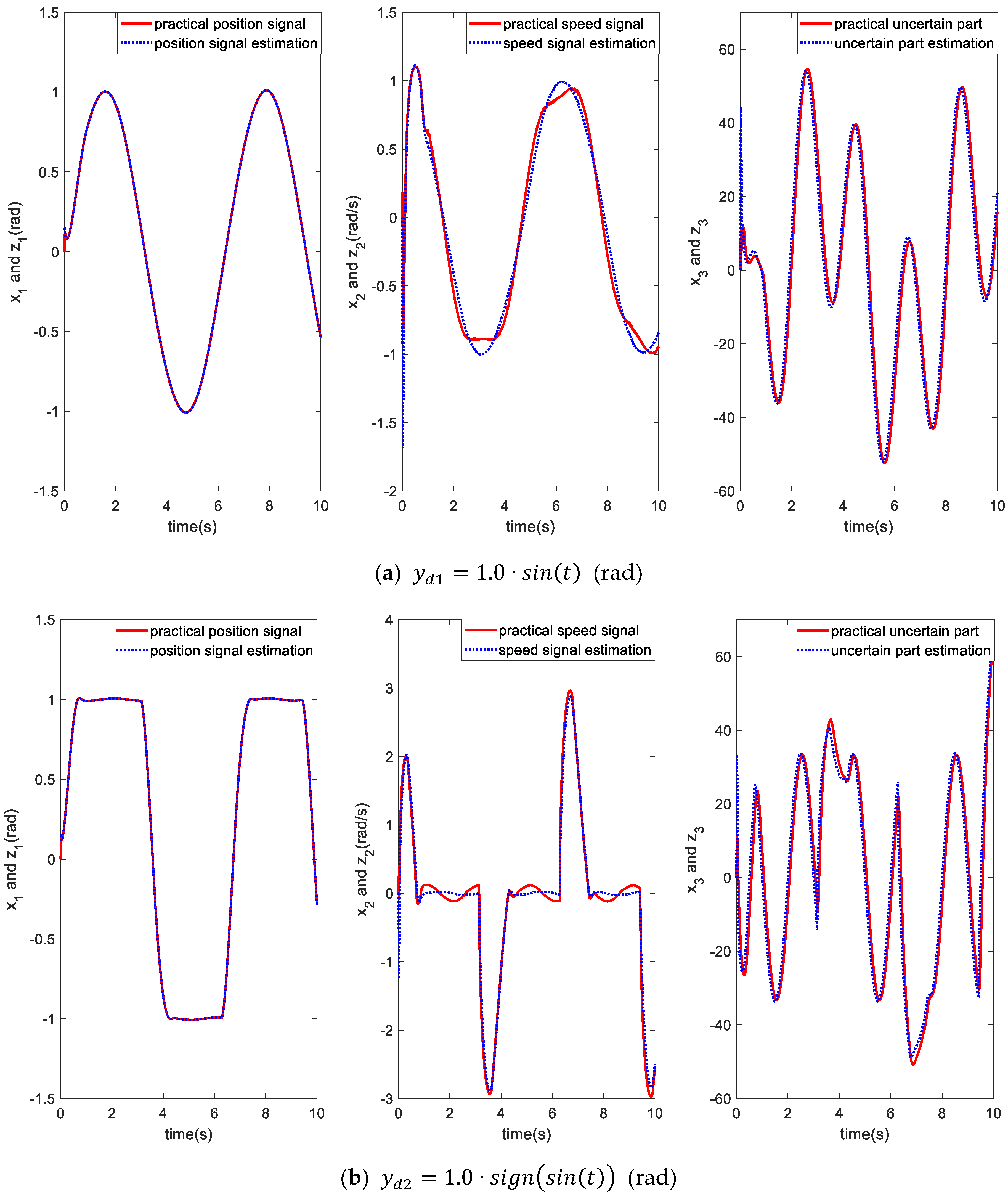
5. Simulation Results and Analysis
6. Experimental Result
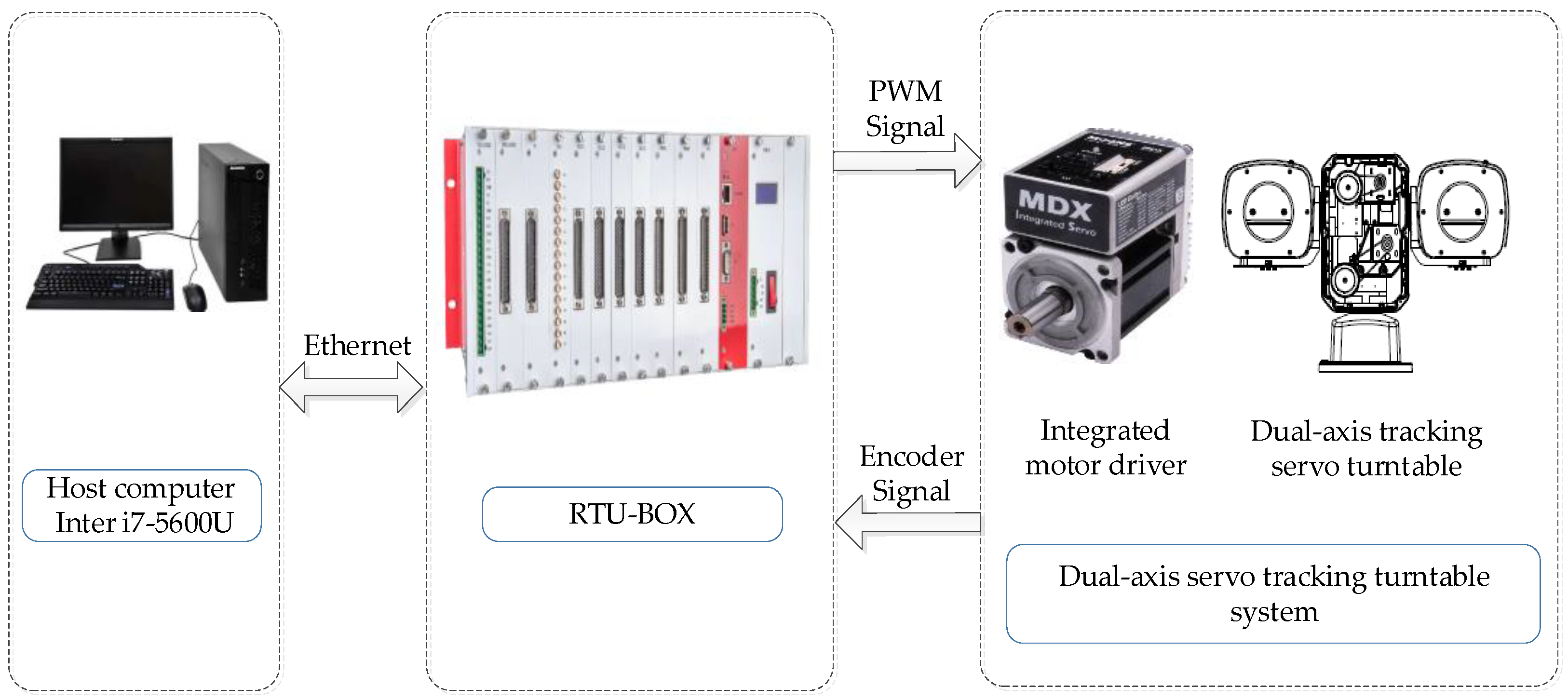
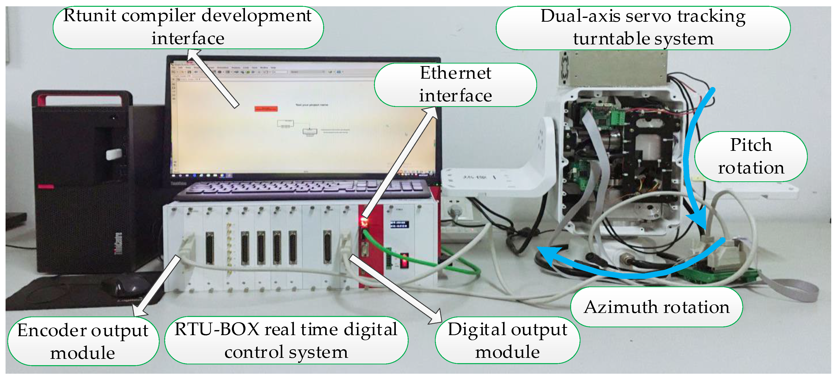
6.1. Experimental Platform
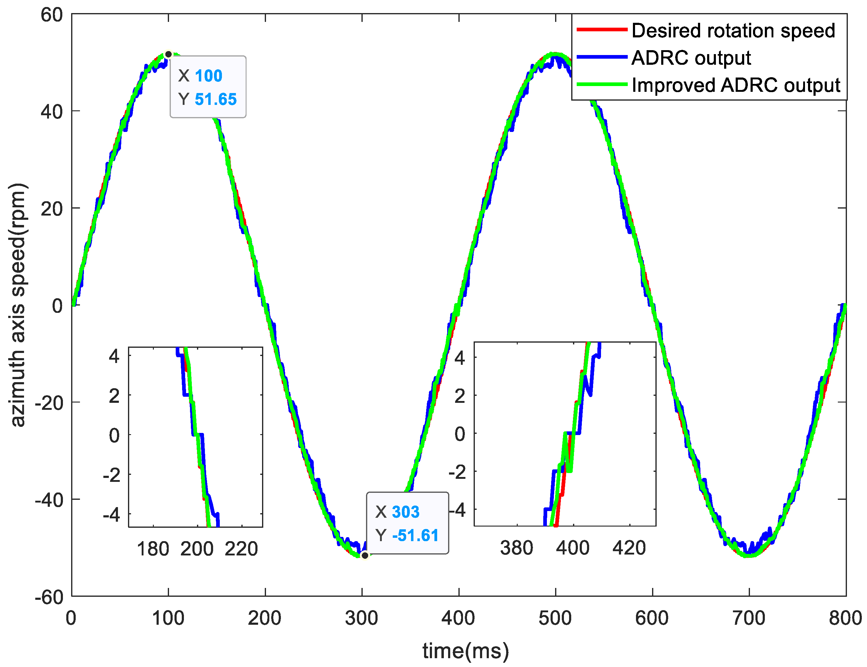
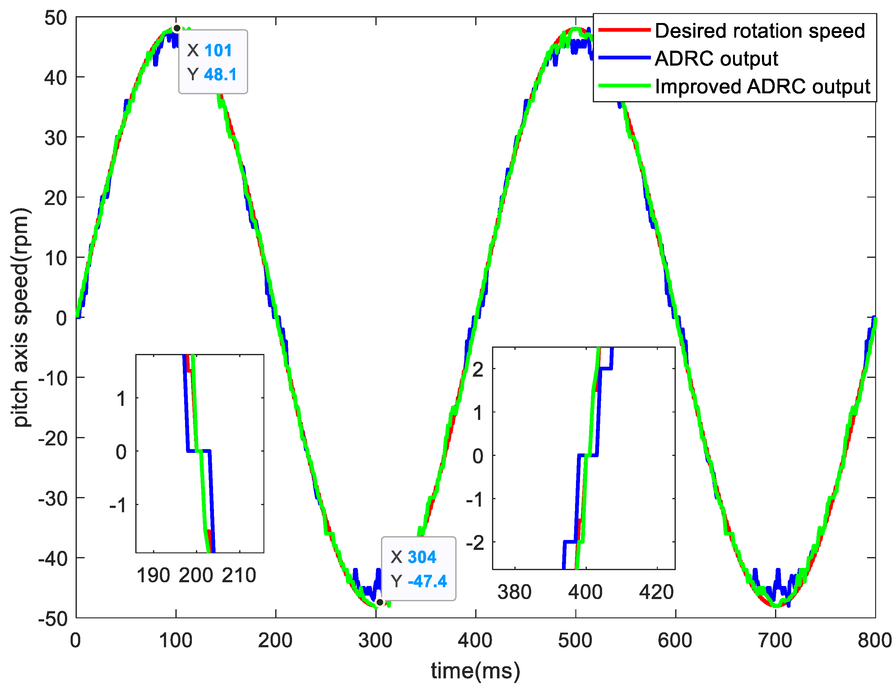
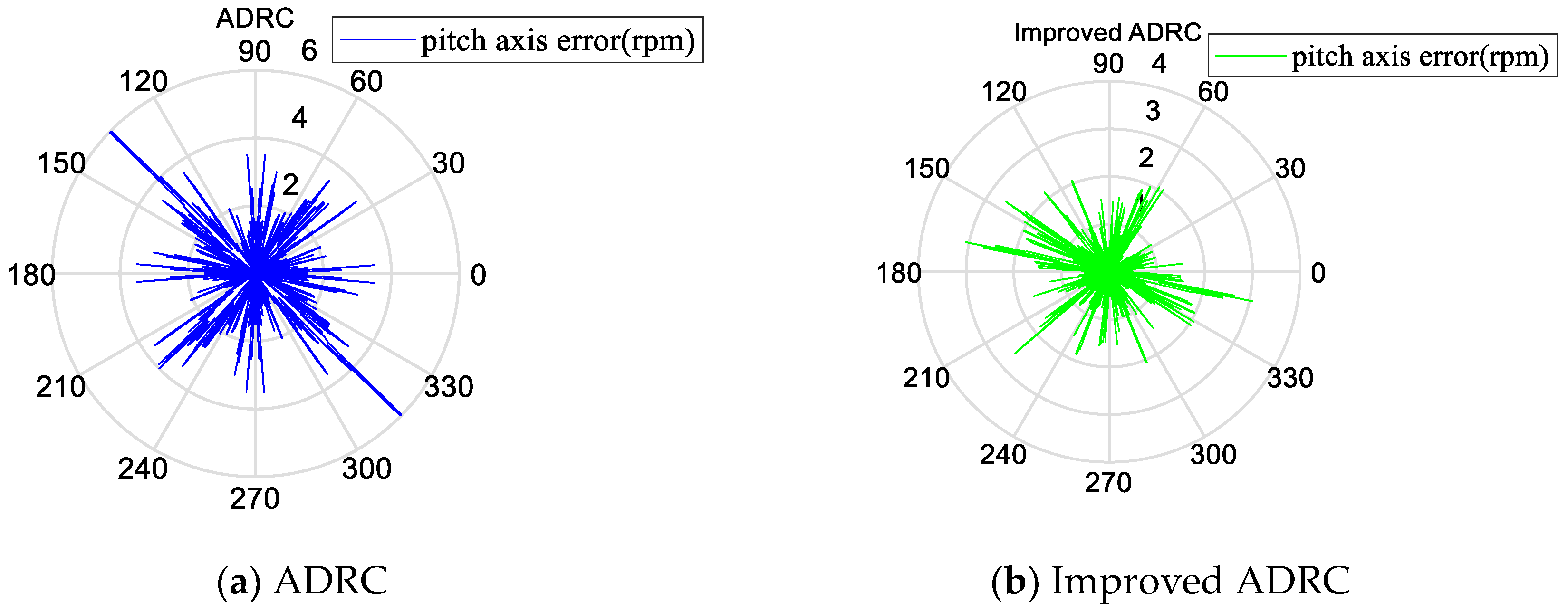
6.2. Experimental Results and Analysis
7. Conclusions
Author Contributions
Funding
Conflicts of Interest
References
- Wei, Q.I.; Zijian, C.U.; Huisheng, Y.A.; Zhenmiao, D.E. High precision phase-domain radial velocity estimation for wideband radar systems. J. Syst. Eng. Electron. 2020, 31, 520–526. [Google Scholar] [CrossRef]
- Belov, M.P.; Phuong, T.H. Servo Speed Control of the Large Radio Telescope Based on Linear Optimal Controller. In Proceedings of the IEEE International Conference on Soft Computing and Measurements, St. Petersburg, Russia, 24 May 2017; pp. 352–355. [Google Scholar]
- Zha, F.; Chang, L.B.; He, H.Y. Comprehensive Error Compensation for Dual-Axis Rotational Inertial Navigation System. IEEE Sens. J. 2020, 20, 3788–3802. [Google Scholar] [CrossRef]
- Zhang, Y.M.; Yan, P.; Zhang, Z. High precision tracking control of a servo gantry with dynamic friction compensation. ISA Trans. 2016, 62, 349–356. [Google Scholar] [CrossRef] [PubMed]
- Wang, S.; Ren, X.; Na, J.; Zeng, T. Extended-State-Observer-Based Funnel Control for Nonlinear Servo- mechanisms with Prescribed Tracking Performance. IEEE Trans. Autom. Sci. Eng. 2017, 14, 98–108. [Google Scholar] [CrossRef]
- Ruderman, M. Tracking Control of Motor Drives Using Feedforward Friction Observer. IEEE Trans. Ind. Electron. 2014, 61, 3727–3735. [Google Scholar] [CrossRef]
- Deng, W.X.; Yao, J.Y. Adaptive integral robust control and application to electromechanical servo systems. ISA Trans. 2017, 67, 256–265. [Google Scholar] [CrossRef] [PubMed]
- Zou, Q.; Sun, L.; Chen, D.; Wang, K. Adaptive Sliding Mode Based Position Tracking Control for PMSM Drive System with Desired Nonlinear Friction Compensation. IEEE Access. 2020, 8, 166150–166163. [Google Scholar] [CrossRef]
- Ting, C.; Chang, Y.; Shi, B.; Lieu, J. Adaptive backstepping control for permanent magnet linear synchronous motor servo drive. IET Electr. Power Appl. 2015, 9, 265–279. [Google Scholar] [CrossRef]
- Zhang, Q.; Wang, Q.J.; Li, G.L. Nonlinear modeling and predictive functional control of Hammerstein system with application to the turntable servo system. Mech. Syst. Signal Proc. 2016, 72–73, 383–394. [Google Scholar] [CrossRef]
- Muddineni, V.P.; Sandepudi, S.R.; Bonala, A.K. Finite control set predictive torque control for induction motor drive with simplified weighting factor selection using TOPSIS method. IET Electr. Power Appl. 2017, 11, 749–760. [Google Scholar] [CrossRef]
- Wang, Y.; Feng, Y.; Zhang, X.; Liang, J. A New Reaching Law for Anti-disturbance Sliding-Mode Control of PMSM Speed Regulation System. IEEE Trans. Power Electron. 2020, 35, 4117–4126. [Google Scholar] [CrossRef]
- Ge, Y.; Yang, L.H.; Ma, X.K. Adaptive sliding mode control based on a combined state/disturbance observer for the disturbance rejection control of PMSM. Electr. Eng. 2020, 102, 1863–1879. [Google Scholar] [CrossRef]
- Lin, C.H.; Ting, J.C. Novel Nonlinear Backstepping Control of Synchronous Reluctance Motor Drive System for Position Tracking of Periodic Reference Inputs with Torque Ripple Consideration. Int. J. Control Autom. Syst. 2019, 17, 1–17. [Google Scholar] [CrossRef]
- Zhang, Q.; Wang, Q.J.; Li, G.L. Switched System Identification Based on the Constrained Multi-objective Optimization Problem with Application to the Servo Turntable. Int. J. Control Autom. Syst. 2016, 14, 1153–1159. [Google Scholar] [CrossRef]
- Han, J.Q. From PID to Active Disturbance Rejection Control. IEEE Trans. Ind. Electron. 2009, 56, 900–906. [Google Scholar] [CrossRef]
- Liu, C.; Luo, G.; Duan, X.; Chen, Z.; Zhang, Z.; Qiu, C. Adaptive LADRC-Based Disturbance Rejection Method for Electromechanical Servo System. IEEE Trans. Ind. Appl. 2020, 56, 876–889. [Google Scholar] [CrossRef]
- Han, J.; Wang, H.; Jiao, G.; Cui, L.; Wang, Y. Research on Active Disturbance Rejection Control Technology of Electromechanical Actuators. Electronics 2018, 7, 174. [Google Scholar] [CrossRef] [Green Version]
- Zhao, Z.L.; Guo, B.Z. A Novel Extended State Observer for Output Tracking of MIMO Systems with Mismatched Uncertainty. IEEE Trans. Autom. Control. 2018, 63, 211–218. [Google Scholar] [CrossRef]
- Patelski, R.; Pazderski, D. Improving the Active Disturbance Rejection Controller Tracking Quality by the Input-Gain Underestimation for a Second-Order Plant. Electronics 2021, 10, 907. [Google Scholar] [CrossRef]
- Yuan, M.; Xu, Z.Z. Tracking Control of Single-Axis Feed Drives Based on ADRC and Feedback Linearization. Electronics 2021, 10, 1184. [Google Scholar] [CrossRef]
- De Wit, C.C.; Olsson, H.; Astrom, K.; Lischinsky, P. A New Model for Control of Systems with Friction. IEEE Trans. Autom. Control. 1995, 40, 419–425. [Google Scholar] [CrossRef] [Green Version]
- Zhang, Q.; Wang, Q.J.; Cui, N.H. Identification and control of the motor-drive servo turntable with the switched friction model. IET Electr. Power Appl. 2020, 14, 843–849. [Google Scholar] [CrossRef]
- Dupont, P.; Hayward, V.; Armstrong, B.; Altpeter, F. Single State Elastoplastic Friction Models. IEEE Trans. Autom. Control. 2002, 47, 787–792. [Google Scholar] [CrossRef]
- Hayward, V.; Armstrong, B.; Altpeter, F.; Dupont, P. Discrete-Time Elasto-Plastic Friction Estimation. IEEE Trans. Control Syst. Technol. 2009, 17, 688–696. [Google Scholar] [CrossRef] [Green Version]
- Keck, A.; Zimmermann, J.; Sawodny, O. Friction parameter identification and compensation using the Elastoplastic friction model. Mechatronics 2017, 17, 168–182. [Google Scholar] [CrossRef]
- Zheng, Y.Q.; Zhang, G.S. Quantized adaptive tracking control for nonlinear systems with actuator backlash compensation. J. Frankl. Inst. Eng. Appl. Math. 2019, 356, 8484–8506. [Google Scholar] [CrossRef]
- Jia, X.; Xu, S.; Zhang, Z.; Cui, G. Output feedback robust stabilization for uncertain non-linear systems with dead-zone input. IET Contr. Theory Appl. 2020, 14, 1828–1836. [Google Scholar] [CrossRef]
- Shirvani Boroujeni, M.; Arab Markadeh, G.; Soltani, J.; Blaabjerg, F. Torque ripple reduction of brushless DC motor with harmonic current injection based on integral terminal sliding mode control. IET Electr. Power Appl. 2018, 12, 25–36. [Google Scholar] [CrossRef]
- Zhao, C.; Guo, L. Control of Nonlinear Uncertain Systems by Extended PID. IEEE Trans. Autom. Control. 2021, 66, 3840–3847. [Google Scholar] [CrossRef]
- Elsisi, M.; Mahmoud, K.; Lehtonen, M.; Darwish, M.M.F. Effective Nonlinear Model Predictive Control Scheme Tuned by Improved NN for Robotic Manipulators. IEEE Access. 2021, 9, 64278–64290. [Google Scholar] [CrossRef]
- Yang, Z.; Ji, J.; Sun, X.; Zhu, H.; Zhao, Q. Active Disturbance Rejection Control for Bearingless Induction Motor Based on Hyperbolic Tangent Tracking Differentiator. IEEE J. Emerg. Sel. Top. Power Electron. 2020, 8, 2623–2633. [Google Scholar] [CrossRef]
- Liu, B.Y. Speed Control for the Pitching Axis of a Remote Sensing Camera Using an Improved Active Disturbance Rejection Controller. Int. J. Control Autom. Syst. 2020, 18, 2360–2374. [Google Scholar] [CrossRef]
- Naghdi, M.; Sadrnia, M.A. A novel fuzzy extended state observer. ISA Trans. 2020, 102, 1–11. [Google Scholar] [CrossRef] [PubMed]
- Li, J.; Xia, Y.; Qi, X.; Gao, Z.; Chang, K.; Pu, F. Absolute stability analysis of non-linear active disturbance rejection control for single-input-single-output systems via the circle criterion method. IET Contr. Theory Appl. 2015, 9, 2320–2329. [Google Scholar] [CrossRef]
- Li, J.; Qi, X.; Xia, Y.; Pu, F.; Chang, K. Frequency domain stability analysis of nonlinear active disturbance rejection control system. ISA Trans. 2015, 56, 188–195. [Google Scholar] [CrossRef] [PubMed]


| Parameters | Unit | Value |
|---|---|---|
| kg·m2 | 0.00272 | |
| N·m/A | 1.36 | |
| V/(rad/s) | 0.085 | |
| 5.65 | ||
| H | 17.8 | |
| / | 112 |
| Description | Parameters | Value |
|---|---|---|
| Improved ESO | 0.5 | |
| 0.25 | ||
| 0.125 | ||
| 0.01 | ||
| 0.1 | ||
| 54 | ||
| 320 | ||
| 1200 | ||
| SEF | 6 | |
| 1.5 |
| Parameters | Unit | Value |
|---|---|---|
| N·m | 0.0274 | |
| N·m | 0.5724 | |
| rad/s | 0.0387 | |
| / | 250 | |
| / | 2.6 | |
| / | 0.0291 |
| MAX (rad) | MEAN (rad) | RMSE (rad) | |
|---|---|---|---|
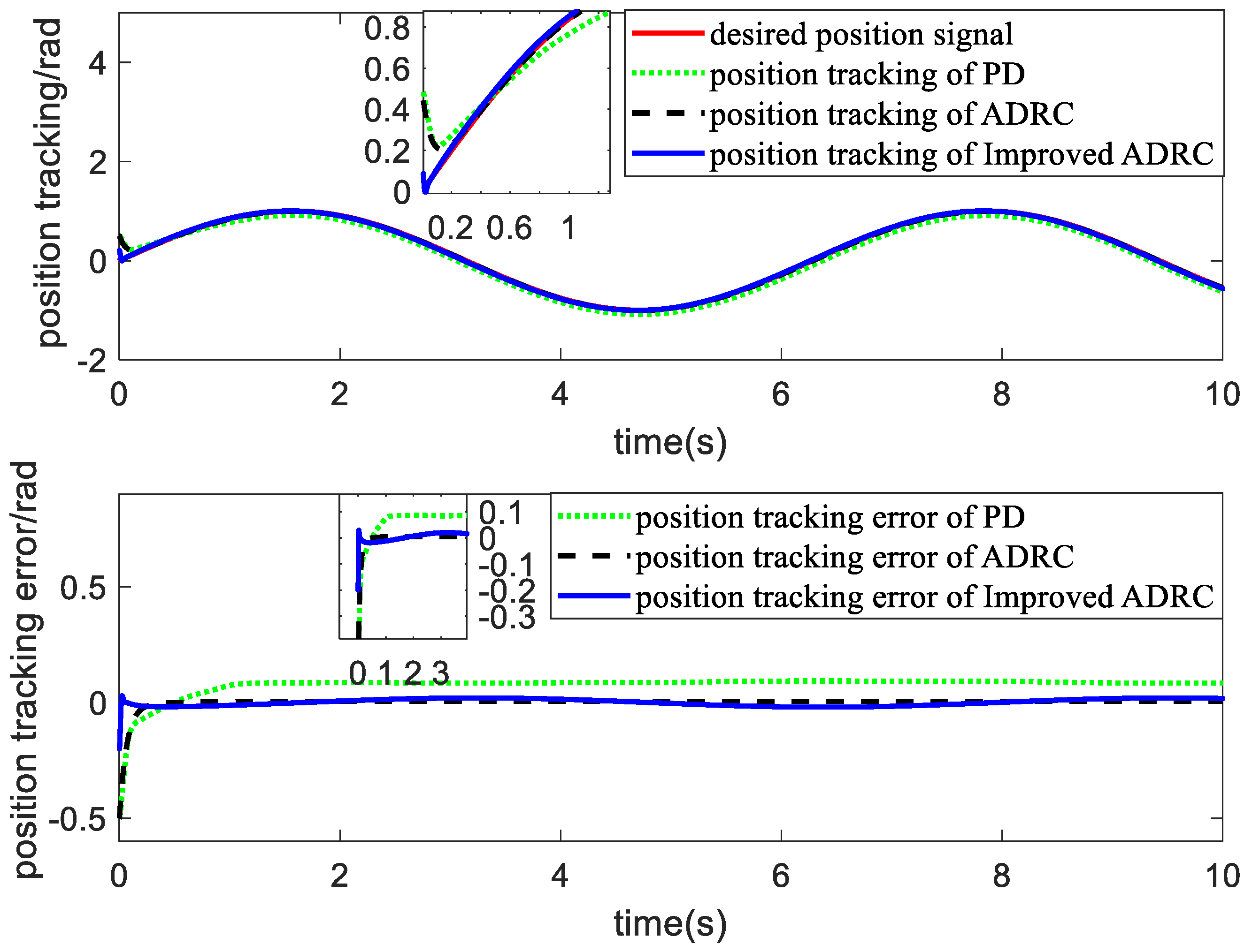
| PD controller | 0.5000 | 0.0145 | 0.1537 |
| ADRC | 0.3566 | 0.0015 | 0.0246 |
| Improved ADRC | 0.2000 | 0.00064 | 0.0161 |
| MAX (rad/s) | MEAN (rad/s) | RMSE (rad/s) | |
|---|---|---|---|
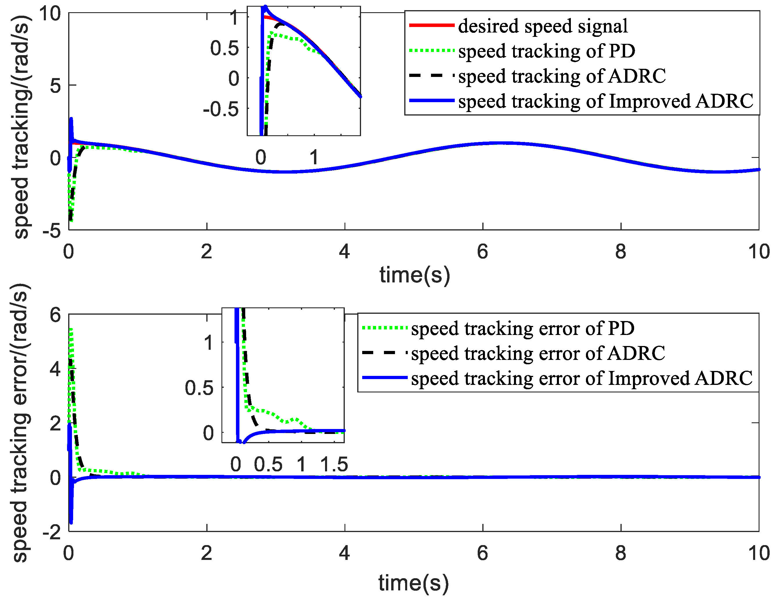
| PD controller | 5.4577 | 0.5464 | 1.4957 |
| ADRC | 4.3488 | 0.0414 | 0.3305 |
| Improved ADRC | 1.9509 | 0.0043 | 0.1081 |
| MAX (rpm) | MEAN (rpm) | RMSE (rpm) | ||
|---|---|---|---|---|
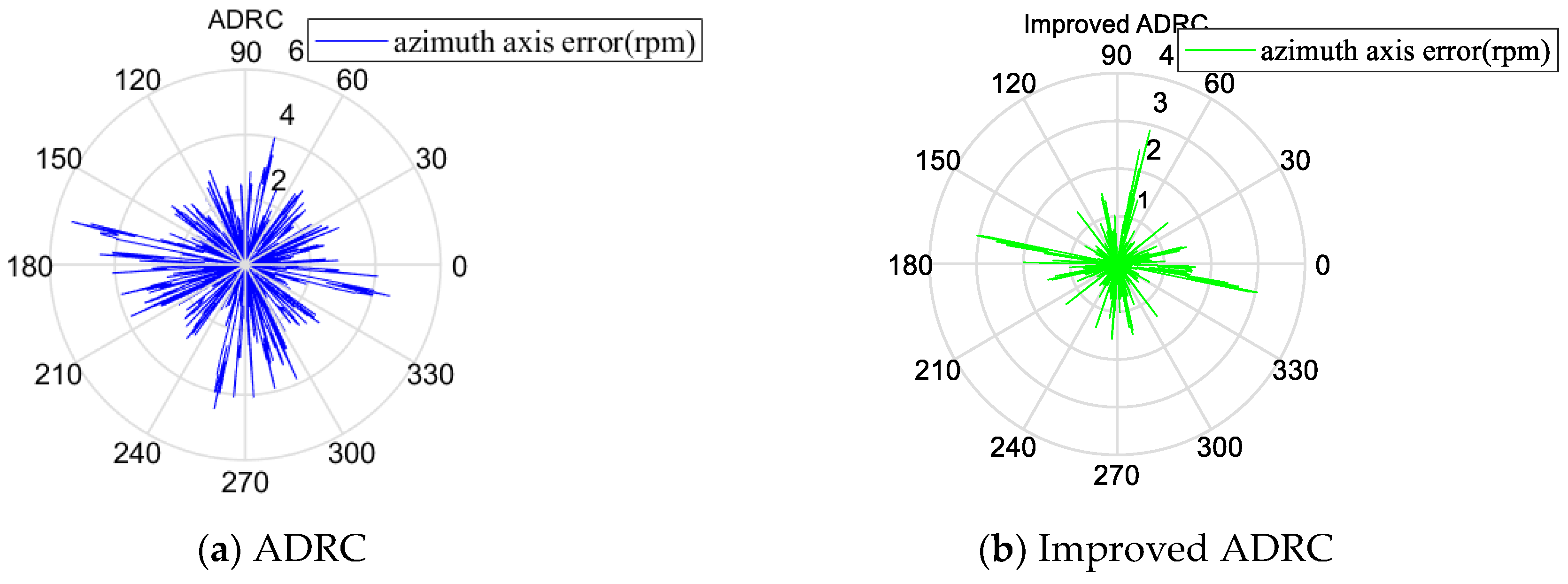
| azimuth axis | ADRC | 4.8421 | 0.0669 | 1.6981 |
| improved ADRC | 2.8823 | 0.0300 | 0.5987 | |
| pitch axis | ADRC | 5.9826 | 0.0526 | 1.5666 |
| improved ADRC | 2.8215 | 0.0463 | 0.8113 |
Publisher’s Note: MDPI stays neutral with regard to jurisdictional claims in published maps and institutional affiliations. |
© 2021 by the authors. Licensee MDPI, Basel, Switzerland. This article is an open access article distributed under the terms and conditions of the Creative Commons Attribution (CC BY) license (https://creativecommons.org/licenses/by/4.0/).
Share and Cite
Zhang, Q.; Wu, X.; Wang, Q.; Chen, D.; Ye, C. Improved Active Disturbance Rejection Control of Dual-Axis Servo Tracking Turntable with Friction Observer. Electronics 2021, 10, 2012. https://doi.org/10.3390/electronics10162012
Zhang Q, Wu X, Wang Q, Chen D, Ye C. Improved Active Disturbance Rejection Control of Dual-Axis Servo Tracking Turntable with Friction Observer. Electronics. 2021; 10(16):2012. https://doi.org/10.3390/electronics10162012
Chicago/Turabian StyleZhang, Qian, Xu Wu, Qunjing Wang, Dijiang Chen, and Chao Ye. 2021. "Improved Active Disturbance Rejection Control of Dual-Axis Servo Tracking Turntable with Friction Observer" Electronics 10, no. 16: 2012. https://doi.org/10.3390/electronics10162012
APA StyleZhang, Q., Wu, X., Wang, Q., Chen, D., & Ye, C. (2021). Improved Active Disturbance Rejection Control of Dual-Axis Servo Tracking Turntable with Friction Observer. Electronics, 10(16), 2012. https://doi.org/10.3390/electronics10162012