
VLSI Architectures of a Wiener Filter for Video Coding

 ,
,  ,
,
Abstract
: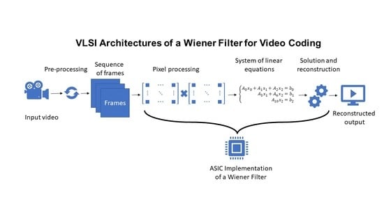
1. Introduction
- The resultant filter has to be separable;
- Each horizontal and vertical filter has to be symmetric;
- Horizontal and vertical filter coefficients cannot take any possible value. Their sum must be exactly S for both filters, where S is a constant value that, for the AV1 implementation, is equal to .
2. Architectural Implementation
- The matrix, a single element of the H matrix, of size 7 × 7.
- The M matrix of size 7 × 7.
- The starting guess vector , composed of 7 elements.
- Matrix B is the coefficients matrix
- Vector A is the vector of constant terms
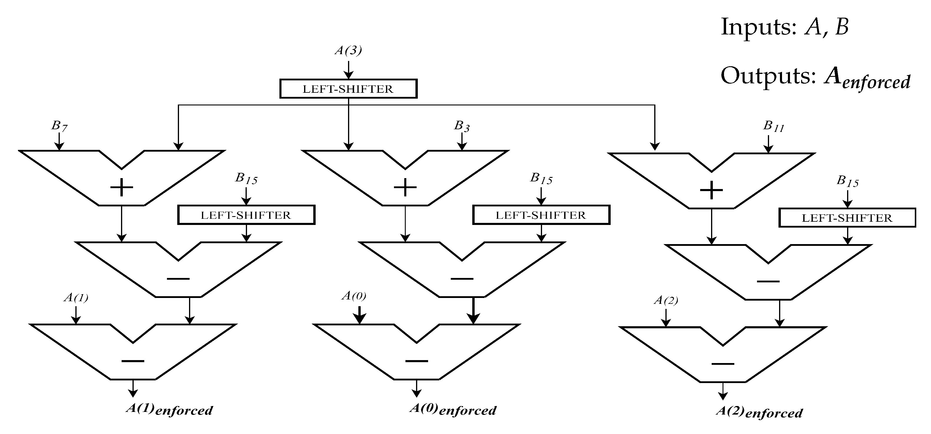
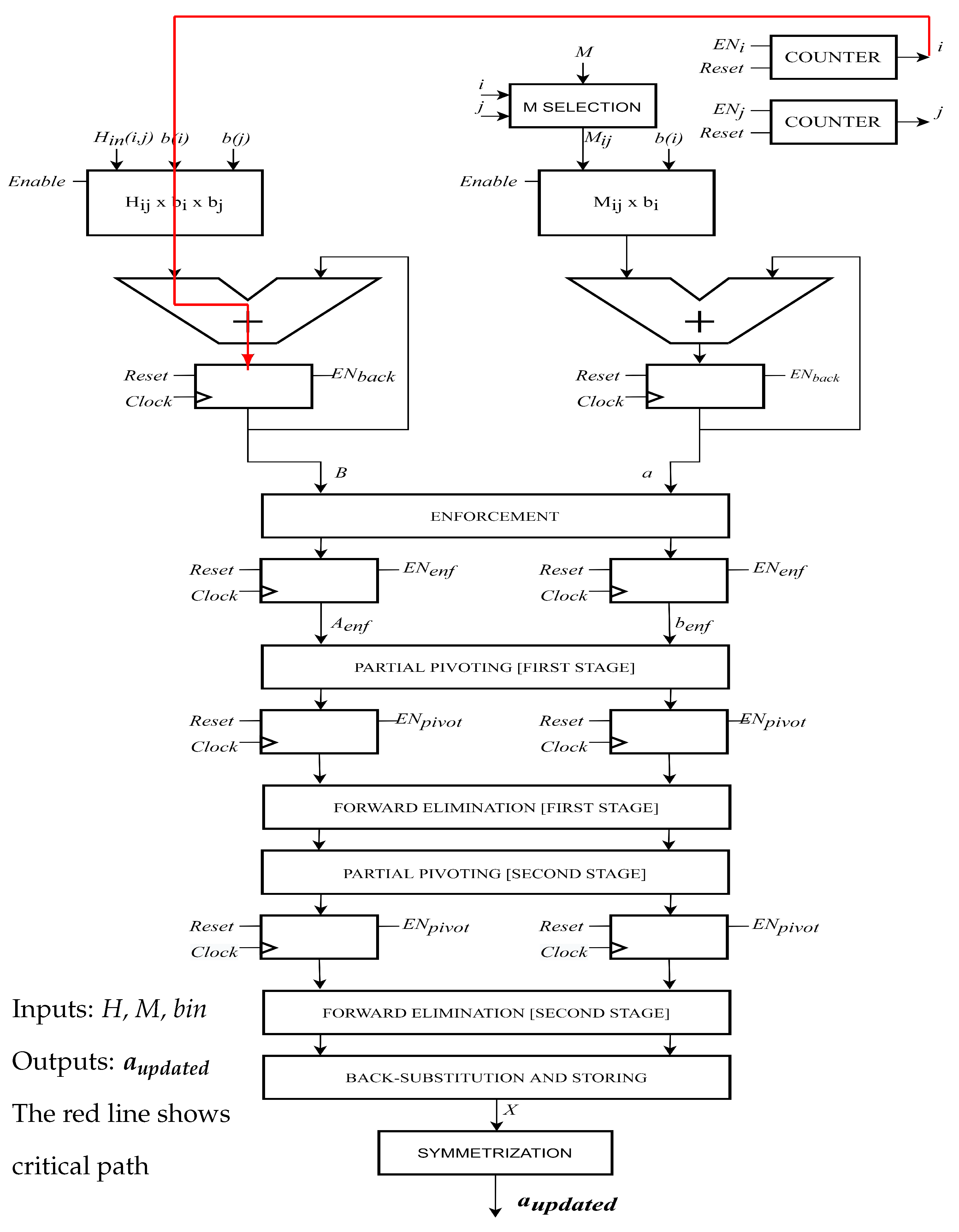
- The Enforcement block compresses the inputs adapting them to the 3-dimensional linear system of equations. By using every component of A, the enforced output vector is computed as represented in Figure 2. The same approach has been used to process the B matrix, exploiting the same flow for every 16 components, reducing them to 9, i.e., 3 × 3. To be coherent with the C model, from now on, B matrix will be called A and vector A will be called b.
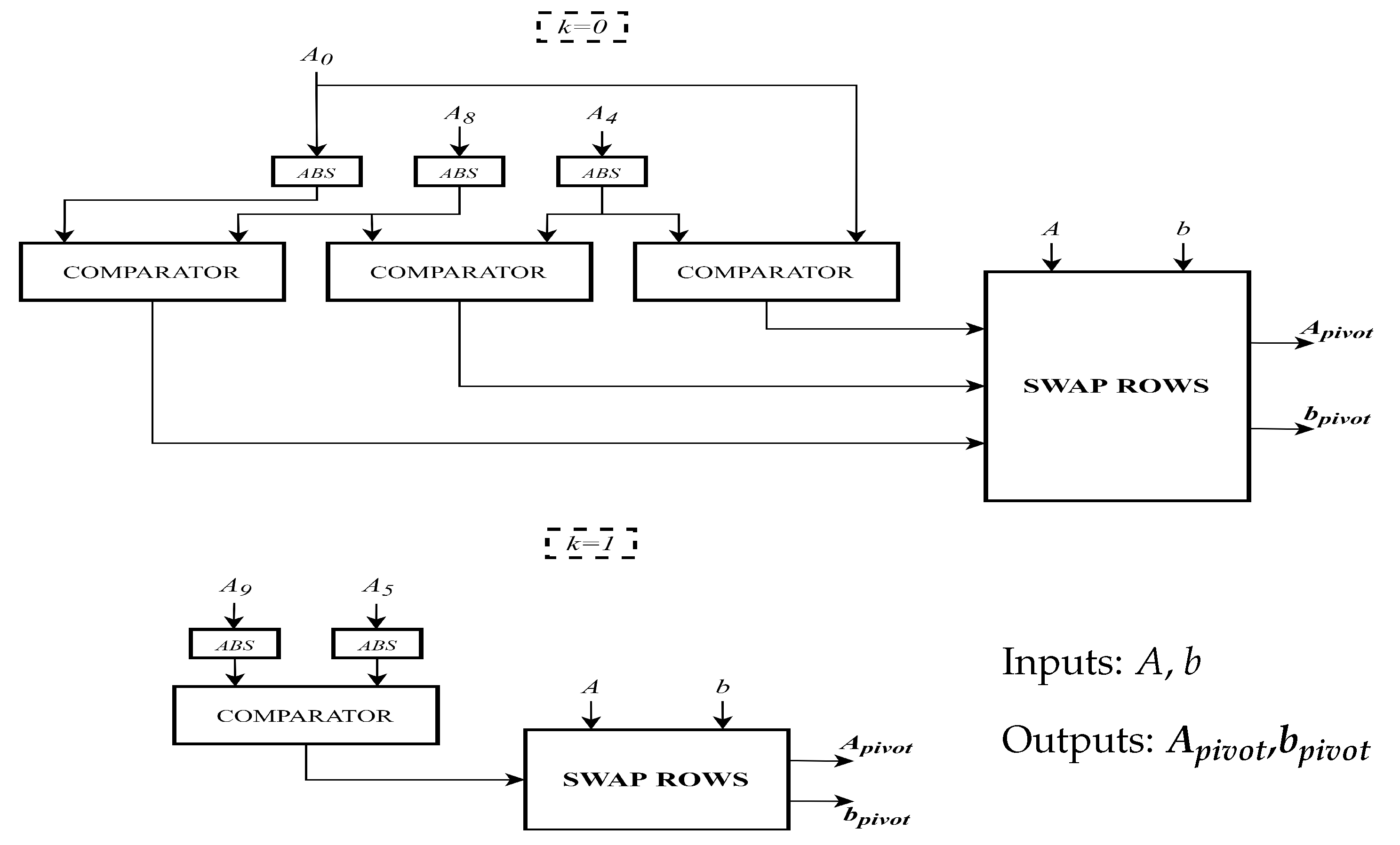
- The Partial Pivoting operation is the simplest block inside the whole architecture as it only involves interchanging rows of the matrix. Figure 3 represents its hardware architecture, where indicates the first stage of Partial Pivoting, while represents the second one. In particular, in the first stage, the absolute values of , and are compared two by two, to find the largest one. Then by using the Swap Rows block, changing the position of b elements based on the outcome of comparators. Similarly, in the second stage, the absolute values of , are compared and eventually swapped to adapt the matrix to be solved with the Gaussian Elimination Method.
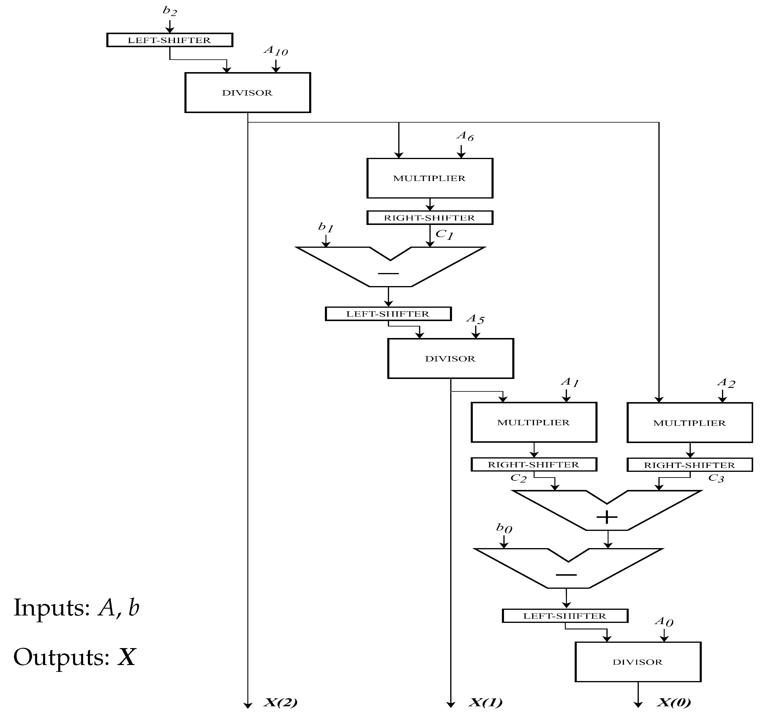
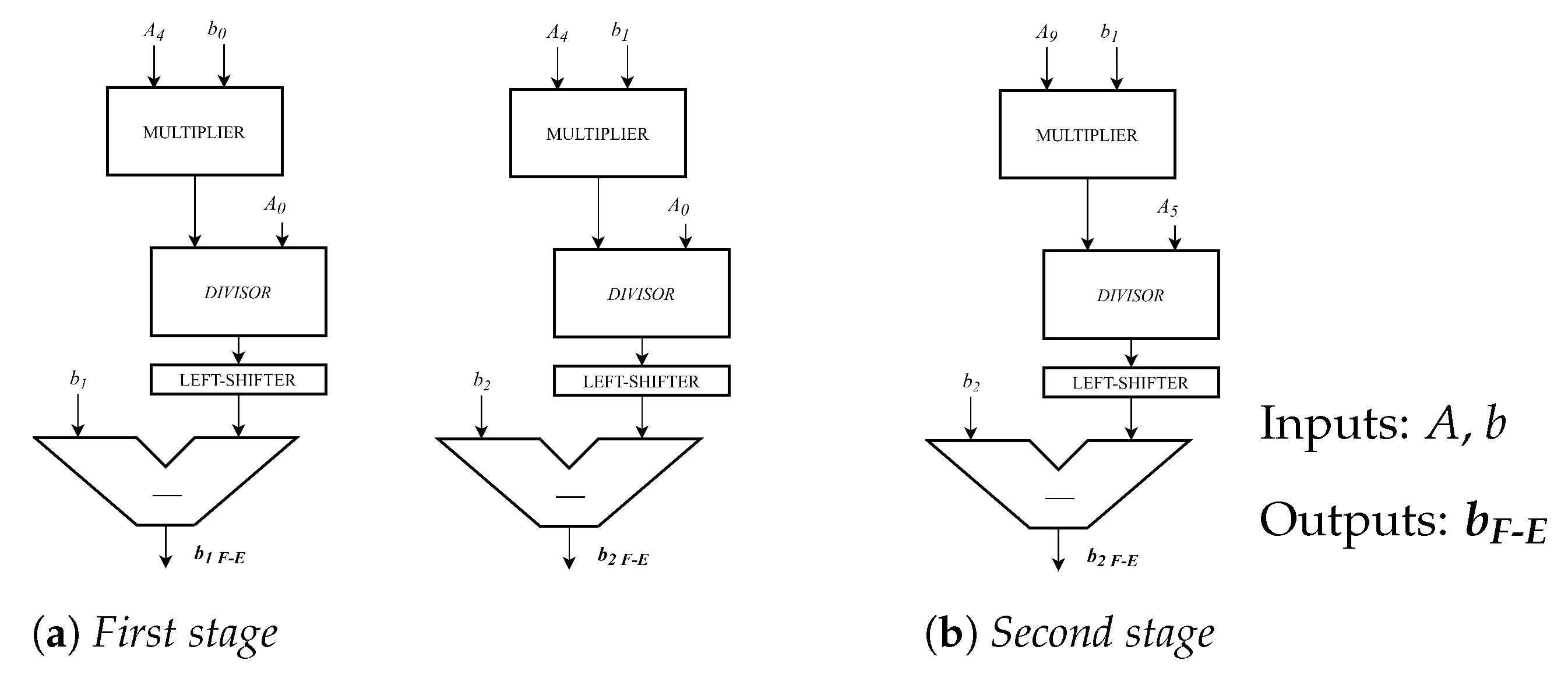
- Forward Elimination is the mathematical step of linear system resolution: it performs multiplication, division and subtraction to combine properly two rows and transforms the matrix as close as possible to an upper triangular form. Figure 4 reports the hardware implementation of the Forward Elimination operation for b vector.
- What remains is to solve a linear system by using the Back-Substitution and storing block:This implemented architecture is shown in Figure 5. From a computational perspective, this block is complex because it involves several expensive operators like dividers and multipliers. Figure 6 shows the update a data path. This contains all the previous blocks combined inside. The critical path is displayed with an arrows going from Counter i to the adder on top left. This is because Hijxbixbj involves cascaded multipliers.
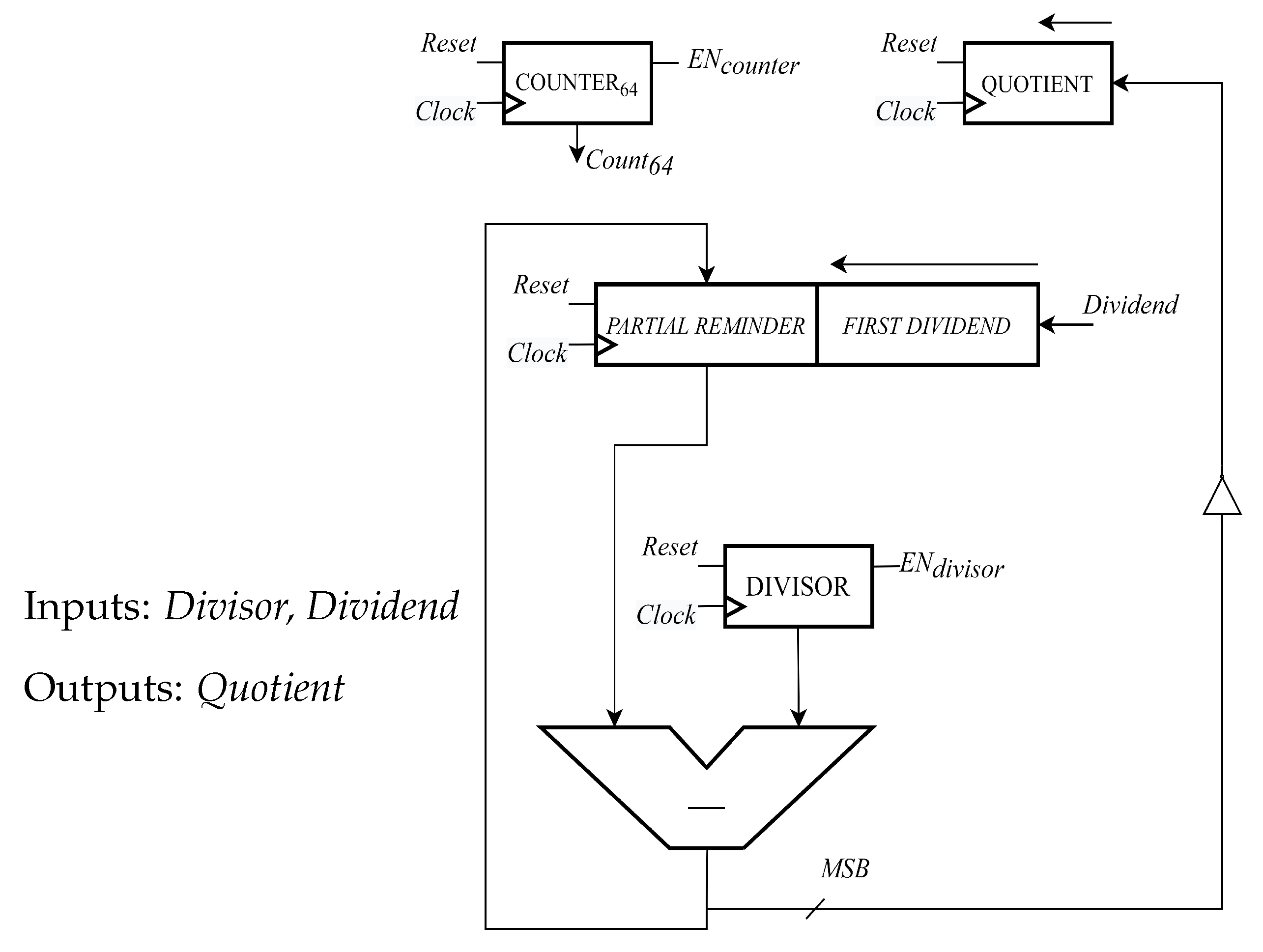
- The dividers in the first basic architecture has been implemented in a purely combinatorial way. In particular, the one used here performs an n-bit division exploiting consecutive operations of addition and subtraction.
2.1. High Speed Architecture
- The length of the combinational paths;
- The combinational dividers.
3. Implementation Results
High Speed Architecture
4. Elaboration for a Real-Time Video Sequence
5. Conclusions
Author Contributions
Funding
Acknowledgments
Conflicts of Interest
References
- Mozilla Research. Available online: https://research.mozilla.org/av1-media-codecs/ (accessed on 18 December 2020).
- Chen, Y.; Murherjee, D.; Han, J.; Grange, A.; Xu, Y.; Liu, Z.; Parker, S.; Chen, C.; Su, H.; Joshi, U. An Overview of Core Coding Tools in the AV1 Video Codec. In Proceedings of the Picture Coding Symposium (PCS), San Francisco, CA, USA, 24–27 June 2018; pp. 41–45. [Google Scholar]
- Saldanha, M.; Corrêa, M.; Corrêa, G.; Palomino, D.; Porto, M.; Zatt, B.; Agostini, L. An Overview of Dedicated Hardware Designs for State-of-the-Art AV1 and H. 266/VVC Video Codecs. In Proceedings of the 27th IEEE International Conference on Electronics, Circuits and Systems (ICECS), Scotland, UK, 23–25 November 2020; pp. 1–4. [Google Scholar]
- W3C Patent Policy. Available online: https://www.w3.org/Consortium/Patent-Policy-20040205/ (accessed on 11 January 2021).
- Mukherjee, D.; Li, S.; Chen, Y.; Anis, A.; Parker, S.; Bankoski, J. A switchable loop-restoration with side-information framework for the emerging AV1 video codec. In Proceedings of the IEEE International Conference on Image Processing (ICIP), Beijing, China, 17–20 September 2017; pp. 265–269. [Google Scholar]
- Goldstein, J.; Reed, I.; Scharf, L.; Tague, J. A low-complexity implementation of adaptive Wiener filters. In Proceedings of the Conference Record of the Thirty-First Asilomar Conference on Signals, Systems and Computers (Cat. No. 97CB36136), Pacific Grove, CA, USA, 2–5 November 1997; pp. 770–774. [Google Scholar]
- Goldstein, J.; Reed, I.; Scharf, L. A multistage representation of the Wiener filter based on orthogonal projections. IEEE Trans. Inf. Theory 1998, 44, 2943–2959. [Google Scholar] [CrossRef] [Green Version]
- De Campos, M.; Werner, S.; Apolinario, J. On an efficient implementation of the multistage Wiener filter through Householder reflections for DS-CDMA interference suppression. GLOBECOM’03. In Proceedings of the IEEE Global Telecommunications Conference (IEEE Cat. No. 03CH37489), San Francisco, CA, USA, 1–5 December 2003; pp. 2350–2354. [Google Scholar]
- Dong, J.; Ling, N. An Iterative Method for Frame-Level Adaptive Wiener Interpolation Filters in Video Coding. In Proceedings of the IEEE Workshop on Signal Processing Systems Design and Implementation, Banff, AB, Canada, 2–4 October 2006; pp. 113–117. [Google Scholar]
- Siekmann, M.; Bosse, S.; Schwarz, H.; Wiegand, T. Separable Wiener filter based adaptive in-loop filter for video coding. In Proceedings of the 28th Picture Coding Symposium, Nagoya, Japan, 7–10 December 2010; pp. 70–73. [Google Scholar]
- Elnady, A.; Noureldin, A.; Liu, Y. Implementation of the Wiener Filter for Extracting Power Quality Disturbances. In Proceedings of the IEEE Power Electronics Specialists Conference, Orlando, FL, USA, 17–21 June 2007; pp. 1116–1120. [Google Scholar]
- Pardede, H.; Ramli, K.; Suryanto, Y.; Hayati, N.; Presekal, A. Speech enhancement for secure communication using coupled spectral subtraction and Wiener filter. Electronics 2019, 8, 897. [Google Scholar] [CrossRef] [Green Version]
- Wu, F.; Yang, W.; Xiao, L.; Zhu, J. Adaptive Wiener Filter and Natural Noise to Eliminate Adversarial Perturbation. Electronics 2020, 9, 1634. [Google Scholar] [CrossRef]
- Musznicki, P.; Schanen, J.; Granjon, P.; Chrzan, P. The Wiener filter applied to EMI decomposition. IEEE Trans. Power Electron. 2008, 23, 3088–3093. [Google Scholar] [CrossRef] [Green Version]
- Rajeswari, K.; Krishna, K.; Naveen, V.; Vamsidhar, A. Performance comparison of wiener filter and cls filter on 2d signals. In Proceedings of the Sixth International Conference on Information Technology: New Generations, Las Vegas, NV, USA, 27–29 April 2009; pp. 1244–1249. [Google Scholar]
- Trambadia, S.; Dholakia, P. Design and analysis of an image restoration using wiener filter with a quality based hybrid algorithms. In Proceedings of the 2nd International Conference on Electronics and Communication Systems (ICECS), Coimbatore, India, 26–27 February 2015; pp. 1318–1323. [Google Scholar]
- Chandra, G.V.P.; Yadav, S.; Krishna, A.; Kamaraju, M. Performance of wiener filter and adaptive filter for noise cancellation in real-time environment. Int. J. Comput. Appl. 2014, 97, 16–23. [Google Scholar]
- TSutter, G.; Deschamps, J.; Bioul, G.; Boemo, E. Power aware dividers in FPGA. In Proceedings of the International Workshop on Power and Timing Modeling, Optimization and Simulation, Santorini, Greece, 15–17 September 2004; pp. 574–584. [Google Scholar]
- Kim, S.; Swartzlander, E. Restoring divider design for quantum-dot cellular automata. In Proceedings of the 11th IEEE International Conference on Nanotechnology, Portland, OR, USA, 15–19 August 2011; pp. 1295–1300. [Google Scholar]
- Venkatachalam, S.; Adams, E.; Ko, S. Design of approximate restoring dividers. In Proceedings of the IEEE International Symposium on Circuits and Systems (ISCAS), Hokkaido, Japan, 26–29 May 2019; pp. 1–5. [Google Scholar]
- Petkova, L.; Draganov, I. Noise Adaptive Wiener Filtering of Images. In Proceedings of the 55th International Scientific Conference on Information, Communication and Energy Systems and Technologies (ICEST), Niš, Serbia, 10–12 September 2020; pp. 177–180. [Google Scholar]
- Malarvizhi, S.; Kayalvizhi, R.; Kumar, A.; Topkar, A. Raw Data Processing Using Modern Hardware for Inspection of Objects In X-Ray Baggage Inspection Systems. IEEE Trans. Nucl. Sci. 2021, 68, 1296–1303. [Google Scholar] [CrossRef]
- Doner, T.; Gokcen, D. FPGA-based infrared image deblurring using angular position of IR detector. Vis. Comput. 2020, 37, 2039–2050. [Google Scholar] [CrossRef]
- Neetu, A. Implementation of Wiener Filter on FPGA using Xilinx System Generator for Speech Enhancement. Int. J. Sci. Innov. Res. Stud. 2018, 6, 1–12. [Google Scholar]
- Yasodai, A.; Ramprasad, A. Noise degradation system using Wiener filter and CORDIC based FFT/IFFT processor. J. Cent. South Univ. 2015, 22, 3849–3859. [Google Scholar] [CrossRef]
- Alliance for Open Media Google Git. Available online: https://aomedia.googlesource.com/aom/ (accessed on 12 July 2020).


| Divider | Frequency [MHz] | Latency [us] | Area [um] |
|---|---|---|---|
| Combinational | 15.15 | 29.91 | 87,258.107 |
| Restoring | 153.6 | 1.59 | 3426.346 |
| RD1 [19] | - | 577 | 740.44 |
| RD2 [20] | - | - | 2799 |
| HSF | Clock [ns] | Freq [MHz] | Area [um] | Power [mW] |
|---|---|---|---|---|
| Synthesis | 13.29 | 75.24 | 1,988,927.227 | 12.816 |
| P-and-R | 10.03 | 99.7 | 1,966,505.5 | 1011 |
| Arch | Device | Latency | LUT | FF | DSP | A-L |
|---|---|---|---|---|---|---|
| [ms] | [Cells/s] | |||||
| HSF | FPGA | 0.00159 | 565,181 | 27,423 | 166 | 0.449 |
| WF [21] | CPU | 406.7 | - | - | - | - |
| WF [22] | FPGA | 10 | 3912 | 4109 | 14 | 20.545 |
| WF [23] | FPGA | 4 | - | - | - | - |
| WF [24] | FPGA | 25 | 6721 | 6186 | 16 | 84.013 |
| WF [25] | FPGA | - | 8360 | 2385 | 13 | - |
| Architecture | Resolution | fps | Msamples/Sec 1 |
|---|---|---|---|
| High-Speed | 720 × 480 | 254.452 | 87.94 |
| Final | 720 × 576 | 211.864 | 87.86 |
| 1280 × 720 | 95.328 | 87.85 | |
| 1920 × 1080 | 42.372 | 87.86 | |
| WF [22] (FPGA) | 512 × 640 | - | 3.2 |
| WF [23] (FPGA) | 256 × 256 | 250 | 16.4 |
| WF [25] (FPGA) 2 | 32 × 32 | 4541 | 4.6 |
Publisher’s Note: MDPI stays neutral with regard to jurisdictional claims in published maps and institutional affiliations. |
© 2021 by the authors. Licensee MDPI, Basel, Switzerland. This article is an open access article distributed under the terms and conditions of the Creative Commons Attribution (CC BY) license (https://creativecommons.org/licenses/by/4.0/).
Share and Cite
Walid, W.; Armanno, G.; Di Paola, S.; Ruo Roch, M.; Masera, G.; Martina, M. VLSI Architectures of a Wiener Filter for Video Coding. Electronics 2021, 10, 1961. https://doi.org/10.3390/electronics10161961
Walid W, Armanno G, Di Paola S, Ruo Roch M, Masera G, Martina M. VLSI Architectures of a Wiener Filter for Video Coding. Electronics. 2021; 10(16):1961. https://doi.org/10.3390/electronics10161961
Chicago/Turabian StyleWalid, Walid, Giorgio Armanno, Sandro Di Paola, Massimo Ruo Roch, Guido Masera, and Maurizio Martina. 2021. "VLSI Architectures of a Wiener Filter for Video Coding" Electronics 10, no. 16: 1961. https://doi.org/10.3390/electronics10161961
APA StyleWalid, W., Armanno, G., Di Paola, S., Ruo Roch, M., Masera, G., & Martina, M. (2021). VLSI Architectures of a Wiener Filter for Video Coding. Electronics, 10(16), 1961. https://doi.org/10.3390/electronics10161961