Article

2-D Beam Focusing Control Based on Passive Frequency Selective Surface (FSS)

Department of Electronic Engineering, Kyungnam University, Changwon 51767, Korea
*
Author to whom correspondence should be addressed.
Electronics 2021, 10(16), 1938; https://doi.org/10.3390/electronics10161938
Submission received: 5 July 2021 / Revised: 9 August 2021 / Accepted: 10 August 2021 / Published: 11 August 2021
(This article belongs to the Section Microwave and Wireless Communications)

Abstract

:
In this paper, the novel design methodology of 2-D beam focusing control based on passive frequency selective surface (FSS) is proposed and described. The beam focusing antenna is composed of 1-D array source and 2-D FSS having a good transmittance and a full transmission phase variation of 360°. The 2-D FSS is designed to make the phase of wave radiated by one source be in-phase, so the transmission phase of the 2-D FSS is concave in itself. Then, the designed 2-D FSS is integrated to the 1-D array source and the longitudinal and the transverse beam focusing controls can be achieved by changing the phase shape of the array source. The relation between the focusing point and the phase combination of the sources is analyzed by a parabolic formula, and the performance of the beam focusing control system is confirmed by both simulation and measurement. From both results, it is concluded that the focusing spot can be tuned longitudinally and transversely by the proposed methodology at 5.8 GHz. In addition, the electric field intensity of 1-D array source with 2-D FSS increases by about 35% compared to that of only 1-D array source.

1. Introduction

Since a frequency selective surface (FSS) can manipulate the wave front of transmitted and reflected electromagnetic (EM) waves, the FSS has a wide range of applications in the EM field. Among them, a transmitarray including the FSS has been intensively researched to focus EM radiation from a source antenna. The transmitarray has the design methodology controlling wave front of the source by the FSS and the total phase of the transmitarray is the sum of the phase of wave radiated by the source and the transmission phase of the FSS. The transmitarray can be utilized to a high gain antenna in the far-field region and a beam focusing in the near-field region [1,2,3,4,5,6,7,8,9,10,11,12,13,14]. To achieve the high gain antenna and the beam focusing, the wave fronts of transmitarray have flat and parabolic shapes, respectively, as shown in Figure 1. In particular, it is necessary to change the shape of the parabolic wave front of the transmitarray in order to control the beam focusing. To achieve the beam focusing control at the desired location, there are two kinds of methods. One is to control the wave front shape using an active FSS designed with diodes, varactors, or active materials including piezoelectric and liquid crystal, and so on. These kinds of beam focusing controls, however, might face difficulties in the implementation complexity of the active FSS and the degradation of performance by the losses of active components. The other is to control the shape of the transmission phase by changing the wave front of the array source. The latter also requires active components such as a phase shifter, but it can reduce the number of components. For instance, the former using the active FSS [15,16,17] and the latter need M × N active components and M + N active components to achieve 3-D beam focusing control, respectively.
In this paper, we propose the beam focusing antenna composed of 1-D array source and 2-D FSS to control beam focusing longitudinally and transversely. When the slope of the parabolic wave front controls by input phase of the array source, the focusing point can be moved longitudinally. Similarly, the focusing point can be moved transversely by the parallel movement of the parabolic wave front. The trimmed patch antenna and the FSS with a circular patch array are employed for polarization-independent beam focusing. The operation frequency is 5.8 GHz, and the measured results are in good agreement with the analytic and the full-wave simulated results. In Section 2, the design procedures of the 1-D array source and 2-D FSS are described. The simulated and measured results are discussed in Section 3. Finally, the conclusions are presented in Section 4.

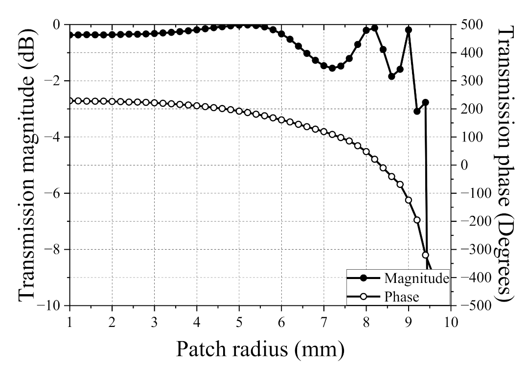
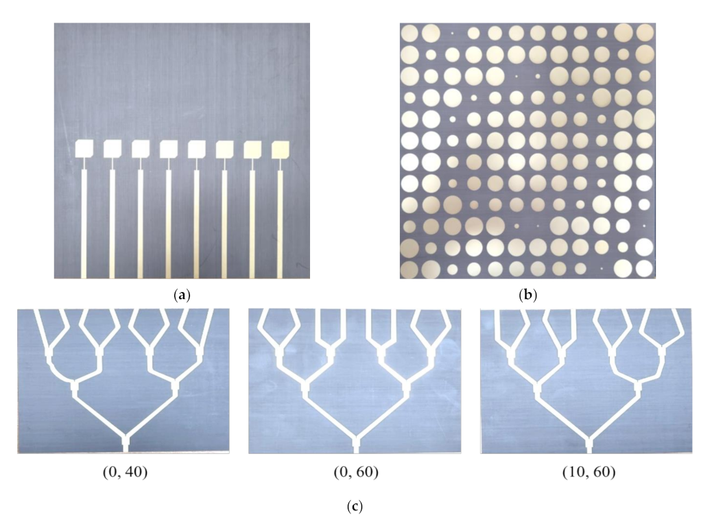
2. Design of Array Source and FSS

To launch a polarization-independent beam, a circularly polarized (CP) microstrip patch antenna with trimmed corners is designed in this paper. The patch antenna is designed as a rectangular patch with a length 16.5 mm of and a width of 16 mm to operate at 5.8 GHz. Truncation of 2.8 mm in length and 2.8 mm in width of rectangular patch has been implemented at two opposite corners. A coaxial feeding is utilized and is 3.25 mm away from center. In addition, the utilized substrate for source antenna is RT/duroid 5880 with a relative permittivity of 2.2 and a loss tangent of 0.0009. The distance between patch antennas is 26 mm and the number of the patch antenna is 8. Moreover, the utilized FSS for the beam focusing is based on a circular patch array [18]. The unit cell of the FSS is formed by four dielectric layers with equally spaced capacitive circular printed patches and has a characteristic of polarization independence due to symmetrical geometry. When the patches are close to each other, the unit cell of the FSS effectively can be operated as a lowpass filter and could have a transmission phase variation of 2π in the pass region. The operation frequency of the FSS is also 5.8 GHz and the utilized substrate is RT/duroid 5880. The thickness and dimension of the unit cell are 12.8 mm and 20 mm (0.38λ0), respectively. The full-wave simulated transmission magnitude and phase of four layers unit cell against a patch radius are plotted by the commercial ANSYS Electronics desktop software. The transmission magnitude remains high (>−2 dB) as the patch radius varies from 1 mm to 9.1 mm, as shown in Figure 2. Furthermore, the transmission phase range of 400° can be obtained by changing the patch radius. The 2-D FSS is designed and fixed to make the phase of wave radiated by one source be in-phase, so the transmission phase of the 2-D FSS is concave in itself. Figure 3 shows the structure of beam focusing control antenna composed of 1-D array source and 2-D FSS. The distance between array source and FSS is decided to be 50 mm (≈1λ0 at 5.8 GHz) considering spillover and taper efficiencies, and the dimension of the FSS with 12 × 12 unit cells is 240 mm × 240 mm, as shown in Figure 3.

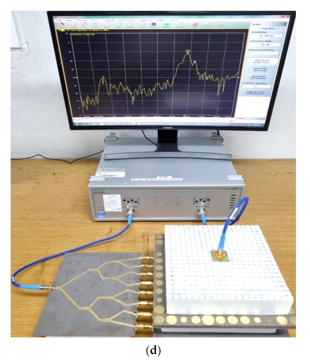
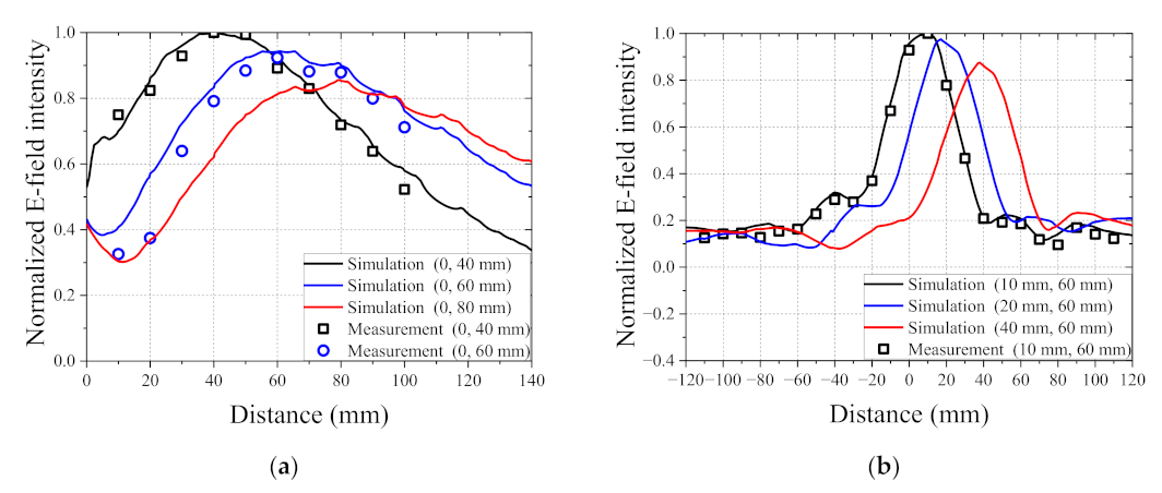
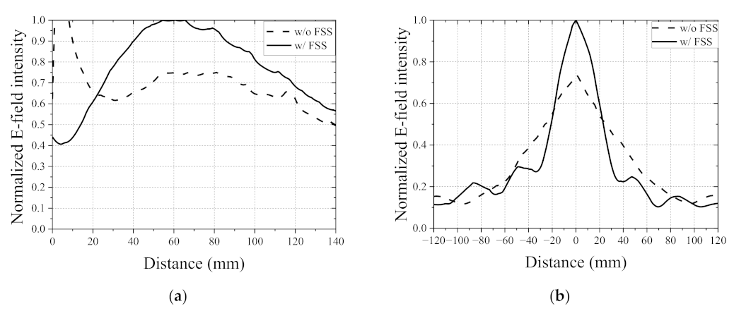
3. 2-D Beam Focusing Control

When the wave front of transmitted wave through the FSS has a shape of parabola, the focusing point can be generated at focal point. Then, a parabola formula can be obtained by Equation (1).
y = 1 4 b x a 2
Origin (0, 0) is the center of a top of FSS. If the wave front is the same as the parabola obtained by Equation (1), a beam can be focused at the point (a, b). The wave front of the transmitted wave through the FSS is the sum of the phase of wave radiated by the source and the transmission phase of the FSS. The wave front of the transmitted wave through the FSS should have a shape of parabola to focus above the FSS. Thus, it is advantageous that the transmission phase of the 2-D FSS has the concave form and the FSS is designed and fixed to make the phase of wave radiated by one source be in-phase. The input phases of each source can be calculated after converting a length to a phase, because the phase is a product of a wavevector with a distance. Table 1 shows input phases of each source against various focal points.
Figure 4 also shows the full-wave simulated electric field intensities on x-z plane at 5.8 GHz. The utilized simulator is commercial ANSYS Electronics desktop software. As shown in Figure 4, we know that the focusing point can be moved longitudinally by changing the slope of the input phase of the array source. Similarly, the focusing point can be moved transversely by the parallel movement of the parabolic wave front. Figure 5 shows the photographs of the fabricated beam focusing control antenna composed of array source, FSS, and 1:8 power divider. Three types of 1:8 power divider were designed to focus on (0 mm, 40 mm), (0 mm, 60 mm), and (10 mm, 60 mm), respectively, instead of feeding network including phase shifters. Moreover, the measured electric field intensity can be obtained using a CP microstrip patch antenna from the experimental setup of Figure 5d. Figure 6 shows the full-wave simulated and measured normalized electric field intensities along the intersection line. The desired analytic focal points are 40 mm, 60 mm, and 80 mm in case of longitudinal control, and simulated focal points are 40 mm, 60 mm, and 78 mm. Moreover, the desired analytic focal points are 10 mm, 20 mm, and 40 mm at height of 60 mm in case of transverse control, and simulated focal points are 10 mm, 18 mm, and 38 mm. A slight discrepancy at transverse beam control may be caused by an asymmetrical shape of parabola due to finite dimension. As the distance from the center increases longitudinally and transversely, the peak of electric field intensity decreases. The measured results are in good agreement with the analytic and the full-wave simulated results. If cross-shaped array source is designed in the beam focusing control system, beam focusing could be controlled 3-dimensionally. To achieve 3-D beam focusing control, a system using the active FSS requires M × N active components, but the proposed system has the advantage that it can be implemented with only M + N active components. To show the high efficiency of the proposed beam focusing control antenna, the performance is compared with that of focusing system using only array source. Table 2 shows input phases of each source without and with FSS to achieve focal point of 60 mm from origin. From the calculated input phase of the source, we compare full-wave simulated normalized electric field intensities between 1-D array source without and with 2-D FSS along the intersection line at 5.8 GHz, as shown in Figure 7. The simulated electric field intensity of 1-D array source with 2-D FSS increases by about 35 % compared to that of only 1-D array source.

4. Conclusions

In this paper, the 2-D beam focusing control method is proposed using 1-D array source and 2-D passive FSS. The relation between the focusing point and the input phases of the sources is analyzed by a parabolic formula. Although 1-D array source is utilized, the focusing efficiency is improved by 2-D FSS. In addition, the proposed control system has an advantage that the number of active components for the beam control can be significantly reduced. The operation frequency is 5.8 GHz and the overall dimension of the proposed transmitarray antenna is 240 mm in dimension and 64.4 mm in height. From the measured results, it is concluded that novel 2-D beam focusing control antenna has good performances and the system would be used in various applications.

Author Contributions

Conceptualization, J.-G.L.; methodology, J.-G.L.; software, J.-H.P.; validation, J.-G.L.; formal analysis, J.-G.L.; investigation, J.-H.P.; resources, J.-H.P.; writing—original draft preparation, J.-H.P.; writing—review and editing, J.-G.L.; visualization, J.-H.P.; supervision, J.-G.L.; project administration, J.-G.L.; funding acquisition, J.-G.L. All authors have read and agreed to the published version of the manuscript.

Funding

This research was funded by the National Research Foundation of Korea (NRF), grant number No. 2020R1F1A1051217.

Acknowledgments

This work was supported by the National Research Foundation of Korea (NRF) grant funded by the Korea government (MSIT) (No. 2020R1F1A1051217).

Conflicts of Interest

The authors declare no conflict of interest.

References

  1. Lima, E.B.; Matos, S.A.; Costa, J.R.; Fernandes, C.A.; Fonseca, N.J.G. Circular polarization wide-angle beam steering at Ka-band by in-plane translation of a plate lens antenna. IEEE Trans. Antennas Propag. 2015, 63, 5443–5455. [Google Scholar] [CrossRef]
  2. Huang, C.; Pan, W.; Ma, X.; Zhao, B.; Cui, J.; Luo, X. Using reconfigurable transmitarray to achieve beam-steering and polarization manipulation applications. IEEE Trans. Antennas Propag. 2015, 63, 4801–4810. [Google Scholar] [CrossRef]
  3. Nicholls, J.G.; Hum, S.V. Full-space electronic beam-steering transmitarray with integrated leaky-wave feed. IEEE Trans. Antennas Propag. 2016, 64, 3410–3422. [Google Scholar] [CrossRef]
  4. Lee, J.G.; Kwon, T.S.; Lee, J.H. Beam pattern reconfigurable circularly polarized transmitarray antenna by rearrangement of sources. Microw. Opt. Technol. Lett. 2019, 61, 999–1003. [Google Scholar] [CrossRef]
  5. Palma, L.D.; Clemente, A.; Dussopt, L.; Sauleau, R.; Potier, P.; Pouliguen, P. Circularly-polarized reconfigurable transmitarray in Ka-band with beam scanning and polarization switching capabilities. IEEE Trans. Antennas Propag. 2017, 65, 529–540. [Google Scholar] [CrossRef]
  6. Pham, K.; Nguyen, N.T.; Clemente, A.; Palma, L.D.; Coq, L.L.; Dussopt, L.; Sauleau, R. Design of wideband dual linearly polarized transmitarray antennas. IEEE Trans. Antennas Propag. 2017, 65, 2022–2026. [Google Scholar] [CrossRef]
  7. Li, H.; Wang, G.; Liang, J.; Gao, X.; Hou, H.; Jia, X. Single-layer focusing gradient metasurface for ultrathin planar lens antenna application. IEEE Trans. Antennas Propag. 2017, 65, 1452–1457. [Google Scholar] [CrossRef]
  8. Wang, W.; Guo, Z.; Zhou, K.; Sun, Y.; Shen, F.; Li, Y.; Qu, S.; Liu, S. Polarization-independent longitudinal multi-focusing metalens. Opt. Express 2015, 23, 29855–29866. [Google Scholar] [CrossRef] [PubMed]
  9. An, W.; Xu, S.; Yang, F.; Li, M. A double-layer transmitarray antenna using malta crosses with vias. IEEE Trans. Antennas Propag. 2016, 64, 1120–1125. [Google Scholar] [CrossRef]
  10. Rahmati, B.; Hassani, H.R. High-efficient wideband slot transmitarray antenna. IEEE Trans. Antennas Propag. 2015, 63, 5149–5155. [Google Scholar] [CrossRef]
  11. Liu, G.; Wang, H.J.; Jiang, J.S.; Xue, F.; Yi, M. A high-efficiency transmitarray antenna using double split ring slot elements. IEEE Antennas Wirel. Propag. Lett. 2015, 14, 1415–1418. [Google Scholar] [CrossRef]
  12. Abdelrahman, A.H.; Elsherbeni, A.Z.; Yang, F. High-gain and broadband transmitarray antenna using triple-layer spiral dipole elements. IEEE Antennas Wirel. Propag. Lett. 2014, 13, 1288–1291. [Google Scholar] [CrossRef]
  13. Tuloti, S.H.R.; Rezaei, P.; Hamedani, F.T. High-efficient wideband transmitarray antenna. IEEE Antennas Wirel. Propag. Lett. 2018, 17, 817–820. [Google Scholar] [CrossRef]
  14. Song, C.; Zhu, L.; Pan, L. Design of transmitarray feed by filtering dielectric antenna for 5G. Int. J. RF Microw. CAE 2020, 30. [Google Scholar] [CrossRef]
  15. Diaby, F.; Clemente, R.; Sauleau, R.; Pham, K.T.; Dussopt, L. 2-bit reconfigurable unit-cell and electronically steerable transmitarray at Ka-band. IEEE Trans. Antennas Propag. 2020, 68, 5003–5008. [Google Scholar] [CrossRef]
  16. Wang, Y.; Xu, S.; Yang, F.; Li, M. A novel 1 bit wide-angle beam scanning reconfigurable transmitarray antenna using an equivalent magnetic dipole element. IEEE Trans. Antennas Propag. 2020, 68, 5691–5695. [Google Scholar] [CrossRef]
  17. Wang, M.; Xu, S.; Yang, F.; Hu, N.; Xie, W.; Chen, Z. A novel 1-bit reconfigurable transmitarray antenna using a C-shaped probe-fed patch element with broadened bandwidth and enhanced efficiency. IEEE Access 2020, 8, 120124–120133. [Google Scholar] [CrossRef]
  18. Li, M.; Behdad, N. Wideband true-time-delay microwave lenses based on metallo-dielectric and all-dielectric lowpass frequency selective surfaces. IEEE Trans. Antennas Propag. 2013, 61, 4109–4119. [Google Scholar] [CrossRef]
Figure 1. Conceptual diagram of wave front of transmitarray: (a) high gain antenna; (b) beam focusing.
Electronics 10 01938 g001
Figure 2. Full-wave simulated transmission magnitude and phase of unit cell of FSS against radius of circular patch at 5.8 GHz.
Electronics 10 01938 g002
Figure 3. Structure of beam focusing control antenna composed of 1-D array source and 2-D FSS: (a) side view; (b) top view.
Electronics 10 01938 g003
Figure 4. Full-wave simulated electric field intensities on x-z plane at 5.8 GHz: (a) longitudinal control; (b) transverse control.
Electronics 10 01938 g004
Figure 5. Photographs of proposed beam focusing control antenna: (a) array source; (b) FSS; (c) 1:8 power dividers; (d) experimental setup.
Electronics 10 01938 g005aElectronics 10 01938 g005b
Figure 6. Full-wave simulated and measured normalized electric field intensities along the intersection line at 5.8 GHz: (a) x-z plane and y-z plane; (b) x-y plane and x-z plane.
Electronics 10 01938 g006
Figure 7. Comparison of full-wave simulated normalized electric field intensities between 1-D array source without and with FSS along the intersection line at 5.8 GHz: (a) x-z plane and y-z plane; (b) x-y plane and x-z plane.
Electronics 10 01938 g007
Table 1. Input phases of each source against various focal points.
Focal Point (mm)1st
Antenna
Phase
2nd
Antenna
Phase
3rd
Antenna
Phase
4th
Antenna
Phase
5th
Antenna
Phase
6th
Antenna
Phase
7th
Antenna
Phase
8th
Antenna
Phase
(0, 40)93.90°44.97°28.96°20.73°20.37°26.84°46.17°106.10°
(0, 60)−26.10°−16.25°6.92°18.28°17.93°4.80°−15.05°−13.90°
(0, 80)−86.10°−46.86°−4.10°17.05°16.70°−6.22°−45.66°−73.90°
(10, 60)29.54°24.32°32.42°28.71°13.29°−14.91°−49.83°−63.75°
(20, 60)123.16°95.33°80.83°54.51°16.48°−34.32°−91.85°−128.38°
(40, 60)292.70°227.20°175.02°112.02°35.32°−53.16°−148.37°−222.57°
Table 2. Input phases of each source without and with FSS.
Focal Point (0, 60 mm)1st
Antenna
Phase
2nd
Antenna
Phase
3rd
Antenna
Phase
4th
Antenna
Phase
5th
Antenna
Phase
6th
Antenna
Phase
7th
Antenna
Phase
8th
Antenna
Phase
w/o FSS240°122.45°44.08°4.90°4.90°44.08°122.45°240°
w/ FSS−26.10°−16.25°6.92°18.28°17.93°4.80°−15.05°−13.90°
Publisher’s Note: MDPI stays neutral with regard to jurisdictional claims in published maps and institutional affiliations.

