Article

Design of a 20 T Class REBCO Insert in a 15 T Low Temperature Superconducting Magnet

1
State Key Laboratory of Tribology, Department of Mechanical Engineering, Tsinghua University, Beijing 100084, China
2
Institute of Plasma Physics, Chinese Academy of Sciences, Hefei 230031, China
*
Author to whom correspondence should be addressed.
Electronics 2021, 10(14), 1741; https://doi.org/10.3390/electronics10141741
Submission received: 14 May 2021 / Revised: 27 June 2021 / Accepted: 6 July 2021 / Published: 20 July 2021
(This article belongs to the Section Quantum Electronics)

Abstract

:
A 20 T REBCO insert magnet has been designed considering a 15 T/150 mm background field generated by an LTS magnet. A two-nested-coil structure was chosen. The target of this project is to generate a 20 T/80 mm user field by inserting the outer MI-REBCO coil (Coil 2) first, then try to reach 35 T by inserting the inner NI-REBCO test coil (Coil 1). Coil 2 will be wound by copper packed, 185-μm thick REBCO tapes co-wound with 50-μm thick Hastelloy tapes. Coil 1 will be no-insulated wound by 65-μm thick REBCO tapes. Two mechanical models were built to estimate the stress distribution inside the HTS coils during operation. The influence of the screening current distribution on stress was discussed. The unbalanced force caused by the coil misalignment was also simulated. The 20 T HTS insert magnet is planned to be built and tested in 2021. The progress of coil winding and preliminary test results at 77 K were presented.

1. Introduction

REBa2Cu3O7−x (REBCO), a high-temperature-superconducting (HTS) material, is believed to be the main candidate conductor for high field magnets [1]. Due to the high in-field critical current density, high upper critical field and high mechanical strength, REBCO tapes are widely used to wind high-field superconducting magnets above 20 T [1,2]. In 2019, National High Magnetic Field Laboratory (NHMFL) successfully built and tested a 45.5 T hybrid magnet with a 14.4 T HTS insert inside a 31.1 T resistive background magnet [3]. The REBCO coil, named ‘little big coil’ (LBC), quenched at a conductor current density of 1420 A/mm2, a peak magnetic stress of 691 MPa and a total strain of 0.38% [3]. A 32 T all-superconducting magnet was also successfully tested in 2017, which consists of a 17 T HTS insert and a 15 T LTS background magnet [4,5,6,7,8]. The REBCO tapes were co-wound with thin 316 L tapes (<12.5 μm) for insulation and reinforcement [9]. A 100-μm thick Cu stabilizer layer was chosen for the REBCO conductors to control the copper current density in the range of 400–450 A/mm2 [10]. MIT also built a series of HTS insert magnets for their 1.3 GHz NMR program. Their previous HTS insert magnet, H800, was designed to provide 18.8 T, quenched in 2018 [11,12]. A new H800 design (H800N) came up after the accident, which was designed to provide 19.7 T [13]. RIKEN proposed a novel winding method called ‘intra-layer no-insulation (LNI)’ to resolve the extremely long charging delay of a simple no-insulation (NI) coil [14]. In 2021, they inserted an LNI-REBCO and an insulated Bi-2223 coil into a 17 T LTS background magnet, which generated a total central field of 30 T for 15 min and quenched at 31.4 T [15]. The Grenoble/CEA group makes great effort in the metal-as-insulation (MI) winding technique, which can decrease the time constant while having the same self-protection aspect compared with the NI winding technique [16,17]. Based on this, they tested an MI HTS insert called the NOUGAT magnet to reach 32.5 T in a 20 T background resistive magnet [18]. SuNAM Co. constructed and tested a 26 T all-GdBCO magnet in 2015, achieving 26.4 T central magnetic field [19]. They used multi-width technique to wind HTS coils in order to control the critical current level. An optimization procedure was also used during the electromagnetic design [20]. Recently, a world-record 32.35 T all-superconducting magnet was successfully demonstrated by the Institute of Electrical Engineering of Chinese Academy of Sciences (IEECAS) in 2019 [21]. In their design, ‘double-winding’ technique was applied to effectively increase the electromagnetic operation margin in local regions. This winding method was firstly tested in a prototype coil that obtained 11.2 T central field at a transport current of 167 A in a 15 T background magnet [22]. Finally, the HTS insert contributed 17.35 T central field with the maximum operation current density of 334.6 A/mm2.
In this work, a 20 T class REBCO magnet was designed as the insert for a 15 T/150 mm background LTS magnet. Considering the space limit of the inner radius of the LTS magnet, we decided to wind an MI-REBCO insert using copper laminated tapes first, which together with the LTS magnet will generate a 20 T/80 mm background field environment. After that, a 15 T NI-REBCO test coil was designed as the innermost insert to generate a 35 T total central field. In order to reduce the hoop stress in the coils, both coils will be wrapped by an over-banding radial build. We calculated the distribution of critical current level based on the nonlinear fit of Ic (B, θ) data from Ref. [23], and built two different mechanical models to describe the stress condition in REBCO tapes. The screening current effect was also considered. The unbalanced magnetic force on the HTS insert aroused by the misalignment between two HTS coils cannot be ignored. Therefore, the conceptual design of the magnet structure is stiff in radial direction and flexible in axial direction, which is also good for quench protection.

2. Electromagnetic Design

2.1. Design Parameters

The 20 T REBCO insert has two nested coils, which will be wound by two different types of REBCO tapes. The outer coil (Coil 2) was designed to provide a stable background field and be efficiently protected from quench; therefore, it will use 4.8 mm wide coated conductors, with 50 μm thick copper strips on both sides to reduce the copper current density. The REBCO tapes will be metal-insulated, as the MI-REBCO coil has smaller charging-delay time constant compared to NI coils, and the co-wound layer can help to compact the coil and reduce the hoop stress compared to insulated coils. The inner one (Coil 1) is not insulated, wound by using 4 mm wide, 65 μm thick REBCO tapes. The specific parameters of the REBCO tapes are listed in Table 1.
The key parameters of the HTS insert magnet are listed in Table 2. Coil 2 consists of 28 double pancakes, designed to generate 5 T central field. The REBCO tape in Coil 2 has a 110 μm thick copper layer, which helps to reduce the engineering current density down to 274.8 A/mm2 in Coil 2. The main reason for controlling the current density is to limit the adiabatic heating during quench. Based on the equations of adiabatic heating under constant-current mode according to Ref. [24], it takes more than 1 s for the resistive zone to heat up from 4.2 K to 200 K. This 1 s heating time is considered to be sufficient for quench protection. In addition, the inter-turn resistance in MI-REBCO coils drops quickly when the coils are cycled, especially in 4.2 K, which will increase the time constant [25]. To reduce this influence, we co-wound Hastelloy tapes instead of stainless steel with REBCO tapes, because the resistivity of Hastelloy is more than two times larger than SS 316 at 4.2 K. Therefore, the inter-turn resistance can be kept relatively high after cycling operation.
Coil 1 consists of 20 double pancakes, designed to contribute 15 T magnetic field, with NI windings. NI-REBCO coils will be wrapped by an 11 mm thick over-banding layer, which is applied to compact the coil as tight as possible within the space limit, and to reduce the hoop stress in Coil 1 as well. Although the NI-REBCO coil can save more space for winding the over-banding layer, the MI technique wind the over-banding layer in a dispersed form, which may have a better effect on strain suppression. This is also one of our follow-up works. The engineering current density in Coil 1 will reach 938.5 A/mm2, which is pretty high. The self-protection merit of NI technology is the key issue to maintain the safe running of Coil 1 [26].

2.2. Safety Considerations

A series of safety-checking simulations have been applied to this magnet design, including critical current level, peak hoop stress in different coils, etc.

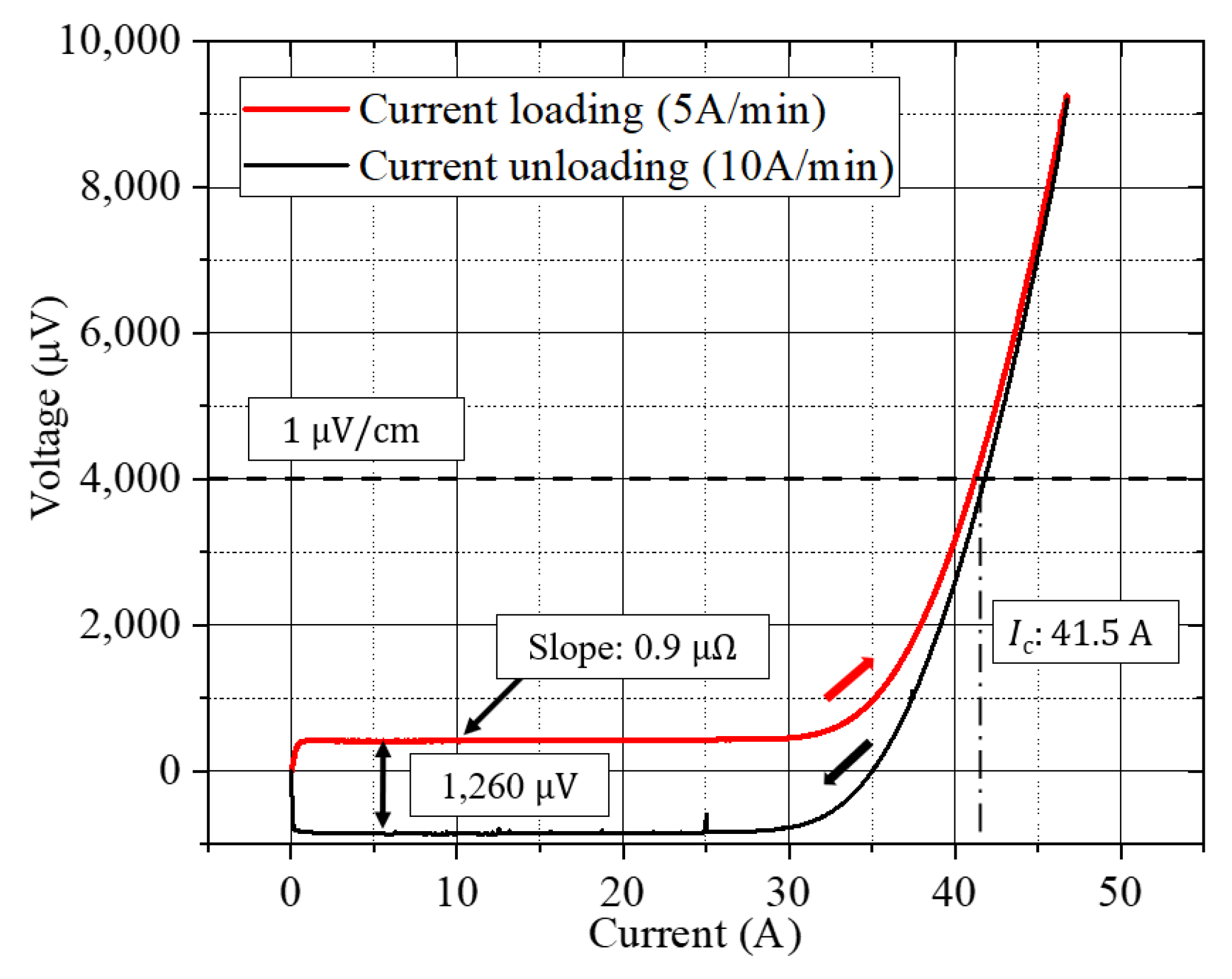
2.2.1. Critical Current Level

The critical current, Ic, varies at different parts of coils due to the influence of magnetic field. The distribution of I/Ic at Iop = 244 A was simulated to characterize the critical current level of the REBCO insert, as shown in Figure 1, based on the nonlinear fit of Ic (B, θ) data from Ref. [23]. The maximum I/Ic is 0.65 in Coil 1 and 0.32 in Coil 2. The upper pancake coils have a much larger I/Ic, but they are still within an acceptable range.

2.2.2. Hoop Stress

We presented two mechanical models to calculate the peak hoop stress (strain) in HTS coils, which are the bulk model and the discrete contact model [27]. The schematic diagrams are shown in Figure 2.
The bulk model assumes that all turns of REBCO coils are bonded together as one single block. The discrete contact model builds up a set of concentric annuli, with simple contact (no friction) between adjacent turns. The simulated hoop strain distribution in the central single pancake of Coil 1 (SP1) and Coil 2 (SP1) are shown in Figure 3, ignoring the effects of screening currents. The strain distribution calculated using Equation (1) is also presented, which assumes that all the turns are discrete [28]
σ φ = B z ( r , z ) J o p r ,
where Bz (r,z) is the axial magnetic field and Jop is the engineering current density.
In the bulk model, the hoop strain in single pancake increases monotonically from outer to inner turns, and reaches a maximum of 0.35% in Coil 1 and 0.20% in Coil 2. Calculating by Equation (1), the hoop strain mostly increases from inner to outer, the maximum reaches 0.28% in Coil 1 and 0.20% in Coil 2. These two models assume that the coil is fully bonded or discrete, respectively, but the discrete contact model shows that the inner part of coils suffer the same hoop strain as Equation (1), after an inflection point, the hoop strain follows the similar trend of the bulk model. This indicates that the two coils are partially compacted and partially separated. The over-banding layer and the winding tension are necessary to strengthen the tightness of coils [29,30].

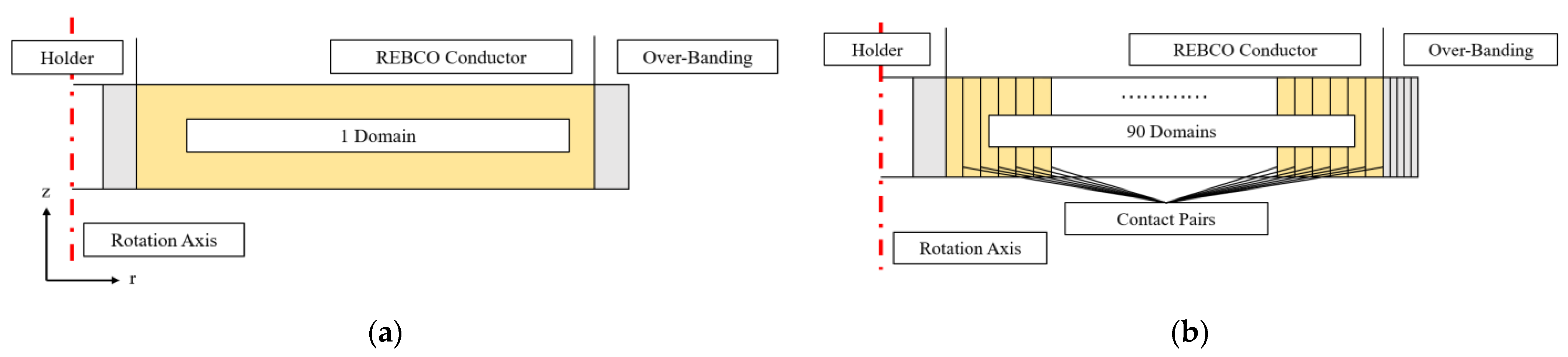
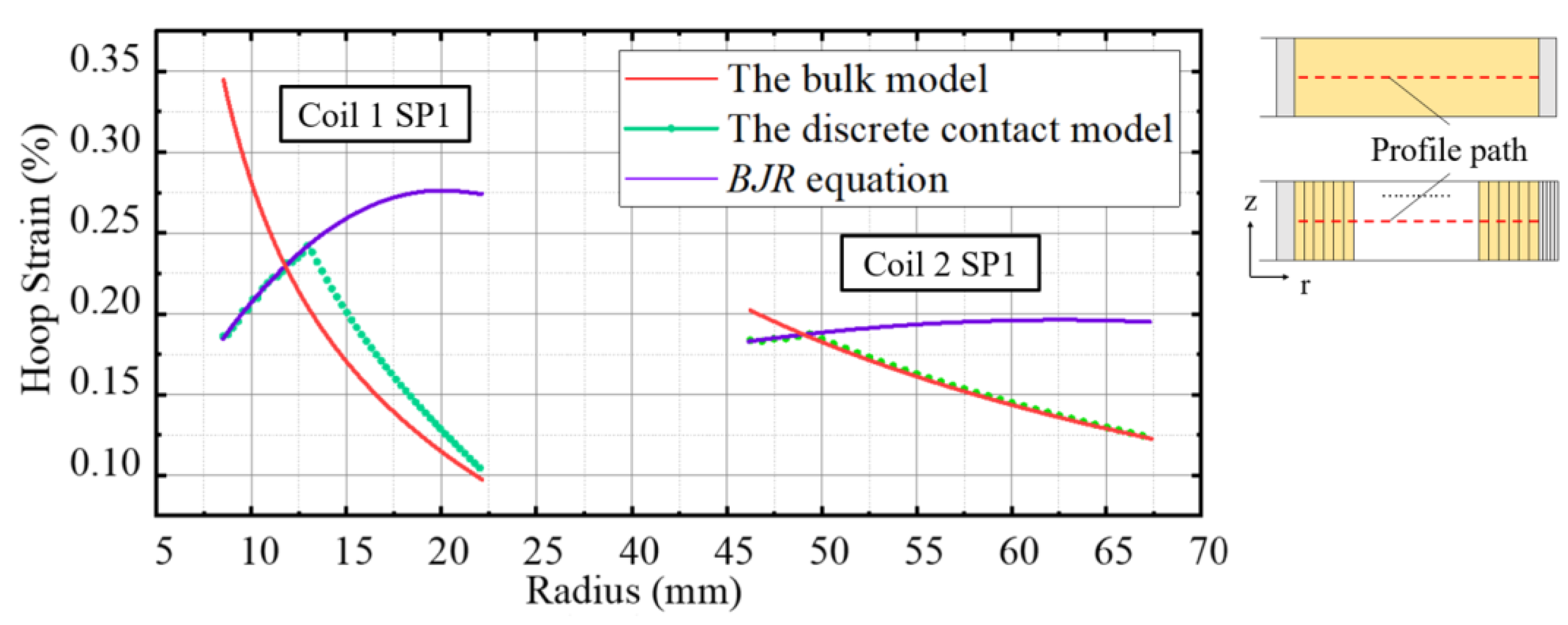
2.2.3. Non-Uniform Current Distribution

The screening current aroused by the perpendicular magnetic field will produce a non-uniform current distribution in REBCO tapes [31,32] and has a considerable influence on the Lorentz force distribution, as shown in Figure 4.
As seen in the uniform current distribution in Figure 4a, a constant force, fr, will be generated under a constant background field, Bz. But considering the screening current effect, radial force fr in the REBCO conductor will distribute unevenly, and even reverse in the tape bottom half, as shown in Figure 4b. The maximum radial Lorentz force can be estimated by [33]
f r J c ( B z , B r ) × B z ,
where Jc is the field dependent critical current density of the REBCO tapes, Bz and Br are the axial and radial magnetic field on tapes, respectively. According to Refs. [33,34], current and field distribution of HTS insert magnet were simulated using the homogeneous T-A formulation. The stress distribution was then simulated by the discrete contact model based on the electromagnetic force from the output of the electromagnetic model. The results of the peak hoop strains in the representative single pancake coils, considering a non-uniform current distribution, are listed in Table 3, compared with the uniform current results from the bulk model.
From Table 3, the peak hoop strain is risky for most commercial REBCO tapes [19]; however, several favorable conditions, such as the effect of winding tension, friction between turns and spacer and epoxy impregnation between turns, might reduce the stress level [35,36,37]. In addition, the deformation of the REBCO tapes could change the angle with respect to the magnetic field, which may affect the screening current distribution and, in turn, influence the hoop stress distribution [38].

3. Conceptual Mechanical Design

The 20 T HTS insert magnet contains an NI inner coil and an MI outer coil, dry wound by REBCO tapes. In the two-nested-coil design, axial and radial misalignments can easily occur considering assembly tolerances and a mismatch of thermal expansion coefficients, which leads to an unbalanced electromagnetic force on the two coils. The unbalanced force on Coil 1 as a function of the radial misalignment Δr and the axial misalignment Δz are shown in Figure 5. According to Figure 5b, the radial force, as an unbalancing force, points to the non-equilibrium direction, and its ratio to the eccentric distance is approximately 200 N/mm; the axial force, as a restoring force, points to the equilibrium direction with the ratio of −400 N/mm.
Based on the result in Figure 5b, the radial unbalanced force will push coils further away from the balanced position, so a radial-rigid-alignment mechanical support is important to ensure the concentric alignment of the two coils. The axial force is towards the balanced point, which is favorable for restoring the axial alignment. Therefore, the axial-support structure can be flexible as millimeter-level axial misalignment is acceptable for the consideration of the mechanical stability.
The mechanical support structure of the 20 T HTS insert magnet was designed following the above objectives of radial-rigid alignment and axial-flexible support. The schematic diagram is shown in Figure 6. Coil 2 is rigidly fixed on the foundation, as the reference of the HTS insert. Coil 1 is radially aligned by the upper justification block and the alignment groove at the bottom. The support rods are spring-supported in the groove, and the upper locating rods of Coil 1 are also spring-linked with the justification block; therefore, the axial position of Coil 1 can be adjusted by the knob on the upper block linked with the upper locating rods of Coil 1. An altimeter will be fixed on the top of Coil 1 to display the relative position of the two coils in the axial direction.
Besides the unbalanced force caused by the misalignment as discussed above, the local force on the cross-over turns and torque on coils accompanying the quench process can also bring serious problems [12,13,39]. To reduce this hidden danger, it is necessary to check the axial strength of the support spring and the shear strength of the coil compression bolt, which is one of the important further works of the mechanical design.

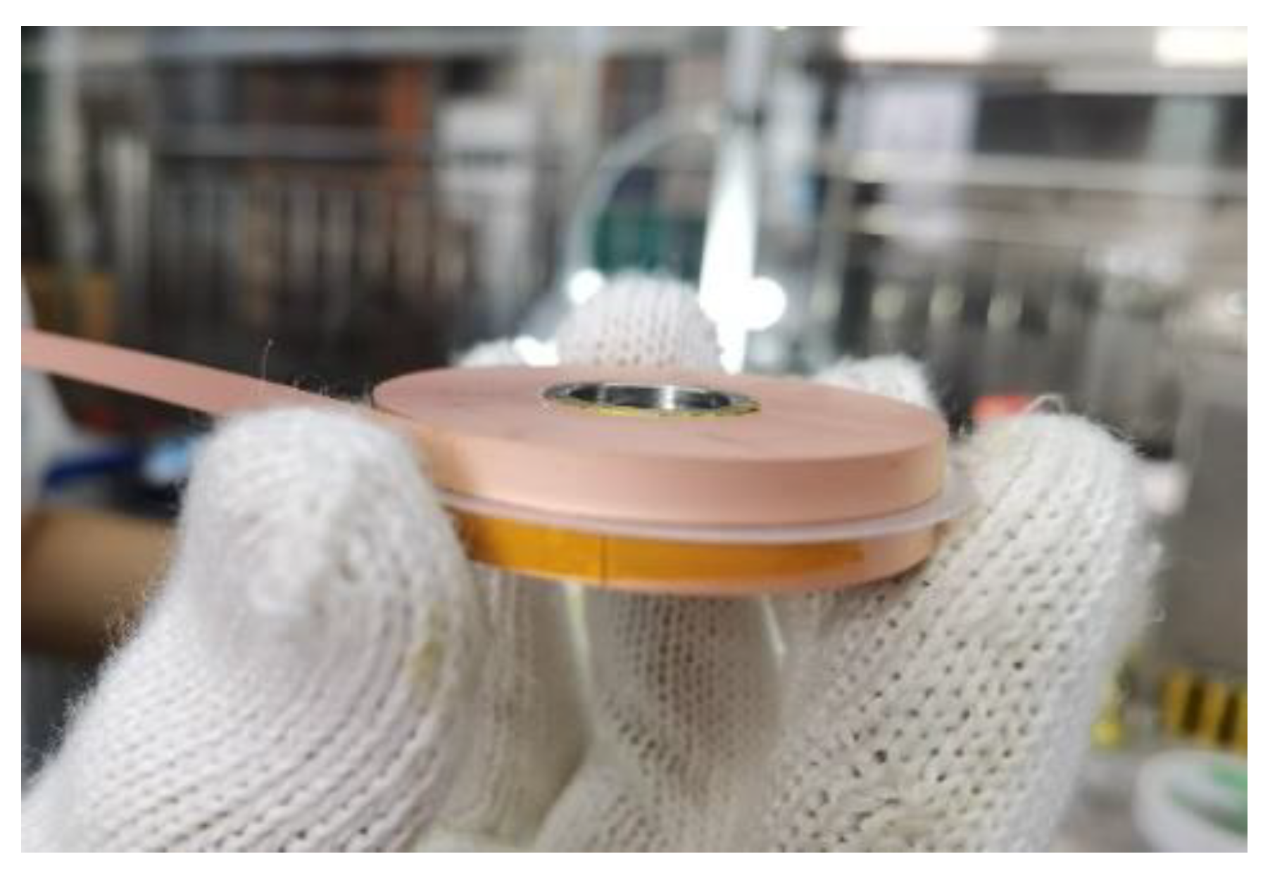
4. Fabrication Progress

The fabrication of the 20 T HTS insert magnet is underway at the Institute of Plasma Physics, Chinese Academy of Sciences (ASIPP) and Tsinghua University. The 20 double pancakes in Coil 1 are being wound on a horizontal winding machine, which makes it easier to control the axial height of each turn to be the same, without bumps. Due to the actual production tolerance of the REBCO tapes’ thickness, each double pancake was controlled to reach the designed outer radius, instead of the designed number of turns. One of the double pancakes is shown in Figure 7.
The transport test was carried out at 77 K to measure the critical current and the total internal resistance of an individual double pancake. A representative test result is shown in Figure 8. During the test, the transport current was loaded at a speed of 5 A/min. After the voltage reached the 1 μV/cm criteria, the current was unloaded at a speed of 10 A/min. The double pancake’s critical current is 41.5 A at 77 K. Due to the loading process being continuous, an induced voltage appeared, and the self-inductance is calculated as 5 mH. The slope of the curve in the superconducting zone reveals that the double pancake has a total internal resistance of 0.9 μΩ. This consists of the inner joint resistance and the turn-to-turn resistance in the NI coil.
In our fabrication of 20 T insert magnet, all the double pancakes will be tested in 77 K individually. After all the double pancakes are wound, Coil 1 and Coil 2 will be tested in 4.2 K liquid helium respectively.

5. Conclusions

We completed the electromagnetic design and conceptual mechanical design of a 20 T two-nested-coil REBCO insert in a 15 T/150 mm LTS background magnet. Two types of REBCO conductors are chosen, which consist of a thin-copper-layer tape to wind the inner NI coil and a thick-copper-layer tape co-wound with Hastelloy tapes for the outer coil. A series of safety simulations were carried out. As for the critical current level, the maximum I/Ic at Iop = 244 A is 0.65 at the upper edge of Coil 1. Two typical mechanical models to simulate the hoop strain distribution were built. The bulk model gives larger peak hoop strain in this magnet, which are 0.35% in Coil 1 and 0.20% in Coil 2. By comparing the results from the discrete contact model with the BJR equation, we found that several turns at the inner part of two coils will be separated during operation, which requires an over-banding radial build to reinforce and compact the coils. After taking the screening current effect into account, the screening-current-induced strain reaches 0.68% in Coil 1, but several favorable conditions are not considered. The unbalanced force caused by the misalignment of two coils is the main consideration for the conceptional mechanical design. The radial unbalancing force was calculated as 200 N/mm, and the axial restoring force was calculated as −400 N/mm. Based on these results, we designed a radial-rigid and axial-flexible support structure.

Author Contributions

Conceptualization, L.S. and T.Q.; data curation, L.S., X.Z. and H.W.; formal analysis, L.S.; investigation, L.S. and X.Z.; methodology, Y.Y.; project administration, H.L. and T.Q.; resources, X.Z. and H.L.; software, L.S., Y.Y. and H.W.; supervision, H.L. and T.Q.; validation, T.Q.; visualization, L.S.; writing—original draft, L.S.; writing—review and editing, H.L. and T.Q. All authors have read and agreed to the published version of the manuscript.

Funding

This work was supported by the Strategic Priority Research Program of the Chinese Academy of Sciences (CAS) under Grant XDB25000000.

Conflicts of Interest

The authors declare no conflict of interest.

References

  1. Bai, H.; Bird, M.D.; Cooley, L.D.; Dixon, I.R.; Kim, K.L.; Larbalestier, D.C.; Marshall, W.S.; Trociewitz, U.P.; Weijers, H.W.; Abraimov, D.V.; et al. The 40 T Superconducting Magnet Project at the National High Magnetic Field Laboratory. IEEE Trans. Appl. Supercond. 2020, 30, 4300405. [Google Scholar] [CrossRef]
  2. Awaji, S.; Watanabe, K.; Oguro, H.; Miyazaki, H.; Hanai, S.; Tosaka, T.; Ioka, S. First performance test of a 25 T cryogen-free superconducting magnet. Supercond. Sci. Technol. 2017, 30, 065001. [Google Scholar] [CrossRef]
  3. Hahn, S.; Kim, K.; Kim, K.; Hu, X.; Painter, T.; Dixon, I.; Kim, S.; Bhattarai, K.R.; Noguchi, S.; Jaroszynski, J.; et al. 45.5-tesla direct-current magnetic field generated with a high-temperature superconducting magnet. Nature 2019, 570, 496–499. [Google Scholar] [CrossRef] [PubMed]
  4. Weijers, H.W.; Markiewicz, W.D.; Gavrilin, A.V.; Voran, A.J.; Viouchkov, Y.L.; Gundlach, S.R.; Noyes, P.D.; Abraimov, D.V.; Bai, H.; Hannahs, S.T.; et al. The 32 T Superconducting Magnet Achieves Full Field. 2017. Available online: https://legacywww.magnet.fsu.edu/mediacenter/publications/reports/2017annualreport/2017-NHMFL-Report399.pdf (accessed on 5 May 2021).
  5. Weijers, H.W.; Markiewicz, W.D.; Gavrilin, A.V.; Voran, A.J.; Viouchkov, Y.L.; Gundlach, S.R.; Noyes, P.D.; Abraimov, D.V.; Bai, H.; Hannahs, S.T.; et al. Progress in the Development and Construction of a 32-T Superconducting Magnet. IEEE Trans. Appl. Supercond. 2016, 26, 4300807. [Google Scholar] [CrossRef]
  6. Weijers, H.W.; Markiewicz, W.D.; Voran, A.J.; Gundlach, S.R.; Sheppard, W.R.; Jarvis, B.; Johnson, Z.L.; Noyes, P.D.; Lu, J.; Kandel, H.; et al. Progress in the Development of a Superconducting 32 T Magnet With REBCO High Field Coils. IEEE Trans. Appl. Supercond. 2014, 24, 4301805. [Google Scholar] [CrossRef]
  7. Voran, A.; Weijers, H.W.; Markiewicz, W.D.; Gundlach, S.R.; Jarvis, J.B.; Sheppard, W.R. Mechanical Support of the NHMFL 32 T Superconducting Magnet. IEEE Trans. Appl. Supercond. 2017, 27, 4300305. [Google Scholar] [CrossRef]
  8. Voran, A.; Markiewicz, W.D.; Weijers, H.W.; Sheppard, W.R.; Jarvis, J.B.; Walsh, R.; McRae, D.; Noyes, P.D. Design and Testing of Terminals for REBCO Coils of 32 T All Superconducting Magnet. IEEE Trans. Appl. Supercond. 2014, 24, 4601204. [Google Scholar] [CrossRef]
  9. Lu, J.; Kandel, H.; Han, K.; Sheppard, W.R.; McRae, D.M.; Voran, A.J.; Pickard, K.W.; Goddard, R.E.; Viouchkov, Y.L.; Weijers, H.W.; et al. Insulation of Coated Conductors for High Field Magnet Applications. IEEE Trans. Appl. Supercond. 2012, 22, 7700304. [Google Scholar] [CrossRef]
  10. Markiewicz, W.D.; Larbalestier, D.C.; Weijers, H.W.; Voran, A.J.; Pickard, K.W.; Sheppard, W.R.; Jaroszynski, J.; Xu, A.; Walsh, R.P.; Lu, J.; et al. Design of a Superconducting 32 T Magnet With REBCO High Field Coils. IEEE Trans. Appl. Supercond. 2012, 22, 4300704. [Google Scholar] [CrossRef]
  11. Bascuñán, J.; Hahn, S.; Kim, Y.; Song, J.; Iwasa, Y. 90-mm/18.8-T All-HTS Insert Magnet for 1.3 GHz LTS/HTS NMR Application: Magnet Design and Double-Pancake Coil Fabrication. IEEE Trans. Appl. Supercond. 2014, 24, 4300904. [Google Scholar] [CrossRef] [PubMed]
  12. Noguchi, S.; Park, D.; Choi, Y.; Lee, J.; Li, Y.; Michael, P.C.; Bascuñán, J.; Hahn, S.; Iwasa, Y. Quench Analyses of the MIT 1.3-GHz LTS/HTS NMR Magnet. IEEE Trans. Appl. Supercond. 2019, 29, 4301005. [Google Scholar] [CrossRef] [PubMed]
  13. Park, D.; Bascunan, J.; Michael, P.C.; Lee, J.; Choi, Y.H.; Li, Y.; Hahn, S.; Iwasa, Y. MIT 1.3-GHz LTS/HTS NMR Magnet: Post Quench Analysis and New 800-MHz Insert Design. IEEE Trans. Appl. Supercond. 2019, 29, 4300804. [Google Scholar] [CrossRef] [PubMed]
  14. Suetomi, Y.; Takahashi, S.; Takao, T.; Maeda, H.; Yanagisawa, Y. A novel winding method for a no-insulation layer-wound REBCO coil to provide a short magnetic field delay and self-protect characteristics. Supercond. Sci. Technol. 2019, 32, 045003. [Google Scholar] [CrossRef]
  15. Suetomi, Y.; Yoshida, T.; Takahashi, S.; Takao, T.; Nishijima, G.; Kitaguchi, H.; Miyoshi, Y.; Hamada, M.; Saito, K.; Piao, R.; et al. Quench and self-protecting behaviour of an intra-layer no-insulation (LNI) REBCO coil at 31.4 T. Supercond. Sci. Technol. 2021, 34, 064003. [Google Scholar] [CrossRef]
  16. Lecrevisse, T.; Iwasa, Y. A (RE)BCO Pancake Winding with Metal-as-Insulation. IEEE Trans. Appl. Supercond. 2016, 26, 4700405. [Google Scholar] [CrossRef] [PubMed]
  17. Lécrevisse, T.; Badel, A.; Benkel, T.; Chaud, X.; Fazilleau, P.; Tixador, P. Metal-as-insulation variant of no-insulation HTS winding technique: Pancake tests under high background magnetic field and high current at 4.2 K. Supercond. Sci. Technol. 2018, 31, 055008. [Google Scholar] [CrossRef]
  18. Fazilleau, P.; Chaud, X.; Debray, F.; Lécrevisse, T.; Song, J.B. 38 mm diameter cold bore metal-as-insulation HTS insert reached 32.5 T in a background magnetic field generated by resistive magnet. Cryogenics 2020, 106, 103053. [Google Scholar] [CrossRef]
  19. Yoon, S.; Kim, J.; Cheon, K.; Lee, H.; Hahn, S.; Moon, S.H. 26 T 35 mm all-GdBa2Cu3O7–x multi-width no-insulation superconducting magnet. Supercond. Sci. Technol. 2016, 29, 04LT04. [Google Scholar] [CrossRef]
  20. Kim, Y.G.; Hahn, S.; Kim, K.L.; Yang, D.G.; Lee, H.G. Design consideration and optimization procedure for a no-insulation multi-width REBCO magnet. Curr. Appl. Phys. 2015, 15, 1134–1138. [Google Scholar] [CrossRef]
  21. Liu, J.; Wang, Q.; Qin, L.; Zhou, B.; Wang, K.; Wang, Y.; Wang, L.; Zhang, Z.; Dai, Y.; Liu, H.; et al. World record 32.35 tesla direct-current magnetic field generated with an all-superconducting magnet. Supercond. Sci. Technol. 2020, 33, 03LT01. [Google Scholar] [CrossRef]
  22. Liu, J.; Wang, Q.; Dai, Y.; Song, S.; Li, L. A 15-T ReBCO Insert for a 30-T All Superconducting Magnet. IEEE Trans. Appl. Supercond. 2017, 27, 4600705. [Google Scholar] [CrossRef]
  23. Hilton, D.K.; Gavrilin, A.V.; Trociewitz, U.P. Practical fit functions for transport critical current versus field magnitude and angle data from (RE)BCO coated conductors at fixed low temperatures and in high magnetic fields. Supercond. Sci. Technol. 2015, 28, 074002. [Google Scholar] [CrossRef] [Green Version]
  24. Iwasa, Y. Protection. In Case Studies in Superconducting Magnets, 2nd ed.; Springer: New York, NY, USA, 2009; pp. 470–473. [Google Scholar]
  25. Lu, J.; Xin, Y.; Lochner, E.; Radcliff, K.; Levitan, J. Contact resistivity due to oxide layers between two REBCO tapes. Supercond. Sci. Technol. 2020, 33, 045001. [Google Scholar] [CrossRef] [Green Version]
  26. Hahn, S.; Park, D.K.; Bascunan, J.; Iwasa, Y. HTS Pancake Coils without Turn-to-Turn Insulation. IEEE Trans. Appl. Supercond. 2011, 21, 1592–1595. [Google Scholar] [CrossRef] [PubMed]
  27. Xia, J.; Bai, H.; Yong, H.; Weijers, H.W.; Painter, T.A.; Bird, M.D. Stress and strain analysis of a REBCO high field coil based on the distribution of shielding current. Supercond. Sci. Technol. 2019, 32, 095005. [Google Scholar] [CrossRef]
  28. Iwasa, Y. Magnets, Fields, and Forces. In Case Studies in Superconducting Magnets, 2nd ed.; Springer: New York, NY, USA, 2009; pp. 98–104. [Google Scholar]
  29. Li, L.; Ni, Z.; Cheng, J.; Wang, H.; Wang, Q.; Zhao, B. Effect of Pretension, Support Condition, and Cool Down on Mechanical Disturbance of Superconducting Coils. IEEE Trans. Appl. Supercond. 2012, 22, 3800104. [Google Scholar]
  30. Guan, M.; Hahn, S.; Bascunan, J.; Wang, X.; Gao, P.; Zhou, Y.; Iwasa, Y. A Parametric Study on Overband Radial Build for a REBCO 800-MHz Insert of a 1.3-GHz LTS/HTS NMR Magnet. IEEE Trans. Appl. Supercond. 2016, 26, 4301205. [Google Scholar] [CrossRef] [PubMed]
  31. Zhang, H.; Zhang, M.; Yuan, W. An efficient 3D finite element method model based on the T–A formulation for superconducting coated conductors. Supercond. Sci. Technol. 2017, 30, 024005. [Google Scholar] [CrossRef]
  32. Liang, F.; Venuturumilli, S.; Zhang, H.; Zhang, M.; Kvitkovic, J.; Pamidi, S.; Wang, Y.; Yuan, W. A finite element model for simulating second generation high temperature superconducting coils/stacks with large number of turns. J. Appl. Phys. 2017, 122, 043903. [Google Scholar] [CrossRef]
  33. Yan, Y.; Xin, C.; Guan, M.; Liu, H.; Tan, Y.; Qu, T. Screening current effect on the stress and strain distribution in REBCO high-field magnets: Experimental verification and numerical analysis. Supercond. Sci. Technol. 2020, 33, 05LT02. [Google Scholar] [CrossRef] [Green Version]
  34. Li, Y.; Park, D.; Yan, Y.; Choi, Y.; Lee, J.; Michael, P.C.; Chen, S.; Qu, T.; Bascuñán, J.; Iwasa, Y. Magnetization and screening current in an 800 MHz (18.8 T) REBCO nuclear magnetic resonance insert magnet: Experimental results and numerical analysis. Supercond. Sci. Technol. 2019, 32, 105007. [Google Scholar] [CrossRef]
  35. Ueda, H.; Awazu, Y.; Tokunaga, K.; Kim, S.B. Numerical evaluation of the deformation of REBCO pancake coil, considering winding tension, thermal stress, and screening-current-induced stress. Supercond. Sci. Technol. 2021, 34, 024003. [Google Scholar] [CrossRef]
  36. Park, J.; Bang, J.; Bong, U.; Kim, J.; Abraimov, D.; Hahn, S. Parametric Study on Effect of Friction and Overbanding in Screening Current Stress of LBC Magnet. IEEE Trans. Appl. Supercond. 2021, 31, 4603205. [Google Scholar] [CrossRef]
  37. Takahashi, S.; Suetomi, Y.; Takao, T.; Yanagisawa, Y.; Maeda, H.; Takeda, Y.; Shimoyama, J.-I. Hoop Stress Modification, Stress Hysteresis and Degradation of a REBCO Coil Due to the Screening Current under External Magnetic Field Cycling. IEEE Trans. Appl. Supercond. 2020, 30, 4602607. [Google Scholar] [CrossRef]
  38. Yan, Y.; Song, P.; Xin, C.; Guan, M.; Li, Y.; Liu, H.; Qu, T. Screening-current-induced mechanical strains in REBCO insert coils. Supercond. Sci. Technol. 2021, 34, 085012. [Google Scholar] [CrossRef]
  39. Michael, P.C.; Park, D.; Choi, Y.H.; Lee, J.; Li, Y.; Bascuñán, J.; Noguchi, S.; Hahn, S.; Iwasa, Y. Assembly and Test of a 3-Nested-Coil 800-MHz REBCO Insert (H800) for the MIT 1.3 GHz LTS/HTS NMR Magnet. IEEE Trans. Appl. Supercond. 2019, 29, 4300706. [Google Scholar] [CrossRef]
Figure 1. The distribution of I/Ic in the HTS insert at Iop = 244 A.
Electronics 10 01741 g001
Figure 2. The schematic diagrams of two mechanical models (for Coil 2). (a) The bulk model. (b) The discrete contact model.
Electronics 10 01741 g002
Figure 3. Hoop strain’s distribution on Coil 1&2 SP 1 using two mechanical models and BJR equation. The legend illustrates the corresponding latitude locations of the profile path.
Electronics 10 01741 g003
Figure 4. The effect of screening current on stress condition. (a) Stress condition without screening current effect. (b) Stress condition considering screening current effect.
Electronics 10 01741 g004
Figure 5. The simulation of unbalanced force on Coil 1 caused by the misalignment of two coils. (a) Schematic diagram of misalignment in coils. (b) Simulation results of the radial and axial unbalanced force between two coils.
Electronics 10 01741 g005
Figure 6. The schematic diagram of 20 T HTS insert magnet mechanical support structure.
Electronics 10 01741 g006
Figure 7. An NI double pancake of Coil 1.
Electronics 10 01741 g007
Figure 8. The transport test result of one double pancake of Coil 1. Current in double pancake was loaded at the speed of 5 A/min and unloaded at 10 A/min.
Electronics 10 01741 g008
Table 1. REBCO Conductor Specifications.
ParameterUnitCoil 1Coil 2
Widthmm44.8
Total thicknessμm65185
Total copper thicknessμm25110
Hastelloy substrate thicknessμm3850
Young modulus (equivalent)GPa152.5110
Required critical current in 5 T perpendicular field, 4.2 KA450450
Required critical tensile stress in 4.2 KMPa770480
Table 2. Key Parameters of 20 T Insert Magnet.
ParameterUnitCoil 1Coil 2
Winding inner radiusmm8.546.2
Winding outer radiusmm22.267.3
Turns per double pancake-21090
Number of double pancakes-2028
Total heightmm168280
Length per double pancakem4065
Over-Banding Thicknessmm113.7
Co-winding Thicknessμm-50
Operation CurrentA244
Engineering Current DensityA/mm2938.5274.8 1
Center Field ContributionT155
InductanceH0.270.85
1 The thickness of co-winding Hastelloy tapes was not considered.
Table 3. Peak Hoop Strain in Different Single Pancakes (SP) Considering Non-uniform Current Distribution.
SP No.Coil 1 (%)Coil 2 (%)
UniformNon-UniformUniformNon-Uniform
10.3390.3130.1920.264
50.3390.4620.1920.392
100.3360.6170.1910.477
150.3280.6850.1890.532
200.3010.4790.1870.559
24--0.1840.566
28--0.1810.532
Publisher’s Note: MDPI stays neutral with regard to jurisdictional claims in published maps and institutional affiliations.

