Article

Power Balance and Power Factors of Distorted Electrical Systems and Variable Speed Asynchronous Electric Drives

1
Electrical Machines Department, Odessa National Polytechnic University, 65044 Odessa, Ukraine
2
Department of Cooperative Studies, Berlin School of Economics and Law, 10315 Berlin, Germany
3
Electrical Machines and Electric Drive Department, Almaty University of Power Engineering and Telecommunications, Almaty 050013, Kazakhstan
4
Telecommunications and Innovative Technologies Department, Almaty University of Power Engineering and Telecommunications, Almaty 050013, Kazakhstan
*
Author to whom correspondence should be addressed.
Electronics 2021, 10(14), 1676; https://doi.org/10.3390/electronics10141676
Submission received: 23 May 2021 / Revised: 29 June 2021 / Accepted: 11 July 2021 / Published: 14 July 2021
(This article belongs to the Section Power Electronics)

Abstract

:
In this study, power quality coefficients that determine the distortion of electrical systems are established. The power factor is chosen as a universal criterion for electromagnetic and electro-energetic compatibility of distorted sources and distorting loads. Mathematical expressions are obtained for its calculation in various cases of electrical systems distortion. As an application example, power balances and power factors of a variable frequency asynchronous drive system are considered. The criterion: the power factor not only determines the energy and electromagnetic compatibility of the drive with power supply, but it also evaluates drive efficiency. Experimental studies were carried out under usage of inexpensive, commonly used measuring devices both on the grid side of the frequency converter and on the asynchronous motor side. The studied coefficients were determined in two ways: measuring instruments and analysis of oscillograms. The second method for determining the above coefficients from oscillograms of currents and voltages also requires finding the total harmonic distortion (THD) of currents and voltages for the corresponding load adjusting points. The similarity of the obtained results shows that both of these methods can be applied. According to the operating mode of the load, the criterion is calculated as an average range in a certain range of speed control, or it is determined by considering a given tachogram of speed changes. The results of experimental studies confirm the correctness of the theoretical provisions.

1. Introduction

The widespread use of power converting equipment and the presence of powerful partial phase loads lead to a distortion of the consumption mode, which, in general, are caused by asymmetry, imbalance, and nonlinearity of the load. In stand-alone systems with finite power sources, such distorting loads are supplied with a distorted three-phase voltage. The distortion of three-phase systems is characterized by power quality indicators, which include the following coefficients: voltage ε U and current ε I unbalance: voltage ε 0 U and current ε 0 I lack of balance: and total harmonic distortion (THD) of voltage and of current.
Analysis through conservative power theory (CPT) confirms that the low load power factor (PF) is mainly due to the nonlinearity [1]. The issues of combating voltage harmonic distortion and improving the quality of autonomous electrical systems are considered in [2]. In [3,4], it is proposed to minimize the total harmonic distortion by using multilevel inverters. The electrical imbalance of a high-speed railroad line is investigated in [5]. The work [6] is devoted to the issues of the quality of electricity during its transmission. The interaction between network and unbalanced loads is studied in [7].
The loads’ effectiveness is determined by their electromagnetic and electro-energetic compatibility with power sources. The universal criterion for the electromagnetic compatibility of distorted sources and distorting loads, considering the adverse effects of asymmetry, imbalance, and higher harmonics, is the power factor. It determines the economic consequences of electricity consumption, and its value depends on the transmission capacity and losses in the grid, and accordingly, the efficiency of loads. Several works are devoted to this issue [8,9]. The power factor is obtained from the analysis of the apparent power, the structure of which is distorted. In addition to active power, there is reactive power due to phase shift and passive powers.
The widespread introduction of adjustable asynchronous electric drives (ASED) in industries, such as transport, the utilities sector, and agriculture, determines the consideration of their effectiveness by defining different criteria [10,11,12]. These criteria can be used both in evaluating the existing ASED and in the development of new ASED. One of the criteria for assessing the efficiency of the ASED can be an energy indicator as the power factor χ. It determines the energy and electromagnetic compatibility of the drive with the mains supply [13]. Meanwhile, the ASED energy efficiency standards, as well as the standards of AC motors, which are powered from the grid [14] and AC motors that are powered by converters [15], are based on the efficiency criterion only. In some works, it is proposed to use the product of the efficiency and the power factor as a criterion for energy efficiency [16,17,18]. Hybrid harmonic management at three levels is the solution to reduce harmonics [19]. The study of imbalance and its influence on the operation of three-phase asynchronous motors due to the formation of reverse sequence currents is considered in [20,21].
The aim of the research is to determine, based on the power balance, the quantitative characteristics of the electro-energetic and electromagnetic compatibility of distorted electrical systems. Using certain indicators of power quality, it is necessary to find an expression for the power factor considering asymmetry, imbalance, and higher harmonics. An experimental verification of the correctness of the expression is required on the example of a frequency-controlled asynchronous electric drive. It is also advisable to consider the criterion in frequency-controlled drives as a medium-range criterion while considering the tachogram of the drive.
The power balance of the distorted electrical system is considered. Therefore, it was determined that the power factor is a quantitative characteristic of energy and electromagnetic compatibility. The expressions of this coefficient are derived through electricity quality indicators, which consider the non-sinusoidality, asymmetry, and unbalance of the system. For example, the power factors were determined experimentally in two ways: on the motor and grid sides. The experimental results confirm the correctness of the theoretical statements. It is proposed, when considering the operation of the electric drive in a certain range, to use the mid-range values of the power factor criterion or to determine the power factor considering the drive’s tachogram.

2. Theoretical Determination of the Power Factor of a Distorted Electrical System

In three-phase four-wire power systems, the neutral wire practically does not participate in the transmission of electricity. Therefore, the square of the apparent power is found through the values of phase voltages and currents. Currents are expressed in terms of the values of the fundamental and higher harmonics. In this case, one should proceed from the assumption that the source has the same spectrum of harmonics as the consumer.
S _ M = U _ A I _ A + U _ B I _ B + U _ C I _ C = = ( U _ A 1 + n U _ A n ) ( I _ A 1 + n I _ A n ) + + ( U _ B 1 + n U _ B n ) ( I _ B 1 + n I _ B n ) + + ( U _ C 1 + n U _ C n ) ( I _ C 1 + n I _ C n ) = = U _ A 1 I _ A 1 + U _ B 1 I _ B 1 + U _ C 1 I _ C 1 + + U _ A 1 n I _ A n + I _ A 1 n U _ A n + n U _ A n n I _ A n + + U _ B 1 n I _ B n + I _ B 1 n U _ B n + n U _ B n n I _ B n + + U _ C 1 n I _ C n + I _ C 1 n U _ C n + n U _ C n n I _ C n .
The last nine terms have the sums of harmonic components that determine passive distortion power D. Assume that the different harmonics of currents and voltages and the same higher harmonics of currents and voltages in the grid do not create active power. If the relative values of harmonics in phases and values of phase voltages and currents are approximately the same:
n U A n U A 1 n U B n U B 1 n U C n U C 1 , n I A n I A 1 n I B n I B 1 n I C n I C 1 .
then we can write the expressions for the power distortion in terms of the coefficients of non-sinusoidal distortion THD [9]:
D I = 3 U 1 I 1 T H D I , D U = 3 U 1 I 1 T H D U , D H = 3 U 1 I 1 T H D I T H D U .
Due to the asymmetry and imbalance of deformed three-phase systems, the symmetric components method is used in the analysis of the fundamental harmonics of voltages and currents. According to this method, voltage and current phasors are decomposed into the sum of the phasors of the zero, direct, and negative sequences. Unity phasor a = ej120° is utilized:
U _ A 1 = U _ 0 + U _ 1 + U _ 2 ; U _ B 1 = U _ 0 + a 2 U _ 1 + a U _ 2 ; U _ C 1 = U _ 0 + a U _ 1 + a 2 U _ 2 .
I _ A 1 = I _ 0 + I _ 1 + I _ 2 ; I _ B 1 = I _ 0 + a 2 I _ 1 + a I _ 2 ; I _ C 1 = I _ 0 + a I _ 1 + a 2 I _ 2 .
when
U _ A 1 I _ A 1 + U _ B 1 I _ B 1 + U _ C 1 I _ C 1 = = 3 U _ 1 I _ 1 + 3 U _ 2 I _ 2 + 3 U _ 0 I _ 0 + + 3 U _ 0 I _ 1 + 3 U _ 0 I _ 2 + + 3 U _ 1 I _ 0 + + 3 U _ 1 I _ 2 + 3 U _ 2 I _ 0 + 3 U _ 2 I _ 1 .
Select the components of the total power. Active power:
P = 3 U 1 I 1 cos φ 1
Reactive power:
Q = 3 U 1 I 1 sin φ 1
“Pulsating” power:
S B = 3 U 2 I 2 + 3 U 1 I 2 + 3 U 2 I 1
“Latent” power:
S 0 = 3 U 0 I 0 + 3 U 0 I 1 + 3 U 1 I 0
“Modular” power:
S m = 3 U 0 I 2 + 3 U 2 I 0
“Pulsating”, “latent”, and “modular” power in autonomous distorted systems are passive or reactive in nature. First, different sequences do not create active power. Secondly, the reverse and zero sequence voltages are formed because of voltage drop due to the currents of these sequences across the corresponding synchronous generator inductive reactances.
As indicated above, the distortion of the power supply system is determined by the corresponding coefficients. Using these coefficients, we can write expressions for some passive components of the apparent power:
S B = 3 U 1 I 1 ( ε U ε I + ε U + ε I )
S 0 = 3 U 1 I 1 ( ε 0 U ε 0 I + ε 0 U + ε 0 I )
S m = 3 U 1 I 1 ( ε U ε 0 I + ε 0 U ε I )
Apparent power:
S M = 3 U 1 I 1 [ 1 + T H D U 2 + T H D I 2 + T H D U 2 T H D I 2 + ( ε U ε I + ε U + ε I ) 2 + ( ε 0 U ε 0 I + ε 0 U + ε 0 I ) 2 + ( ε U ε 0 I + ε 0 U ε I ) 2 ] 1 2
The power factor is found through the distortion factors:
χ = c o s φ 1 [ 1 + T H D U 2 + T H D I 2 + T H D U 2 T H D I 2 + ( ε U ε I + ε U + ε I ) 2 + ( ε 0 U ε 0 I + ε 0 U + ε 0 I ) 2 + ( ε U ε 0 I + ε 0 U ε I ) 2 ] 1 2
A three-phase three-wire system is always balanced, and there are no “latent” and “modulation” components of the apparent power. The power factor is expressed as follows:
χ = c o s φ 1 1 + T H D U 2 + T H D I 2 + T H D U 2 T H D I 2 + ( ε U ε I + ε U + ε I ) 2
If the distortion is determined only by the coefficients of non-sinusoidal distortion, then the power factor will be equal to
χ = c o s φ 1 1 + T H D U 2 + T H D I 2 + T H D U 2 T H D I 2
Considering a system with an infinite power source in which the distorting load is supplied with an undistorted three-phase voltage, the power factor expression is simplified [22]:
χ = c o s φ 1 1 + T H D I 2
Modern semiconductor frequency converters with IGBT transistors allow realizing the most rational control pulse-width modulation. The presence of high-order voltage time harmonics on the terminals of the induction motor, as well as the higher spatial harmonics generated by them, leads to an increase in electrical and magnetic losses, excessive heating, and a decrease in productivity [23]. To determine these parameters, information on motor equivalent circuit for the entire harmonics spectrum when supplying the stator windings is needed [24]. To assess this impact in a specific case, it is necessary to analyze the inverter output voltage influence on the motor, knowing its specific harmonic composition [25].

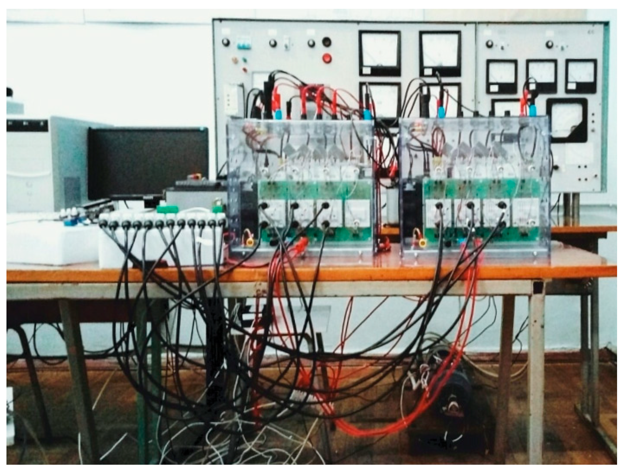
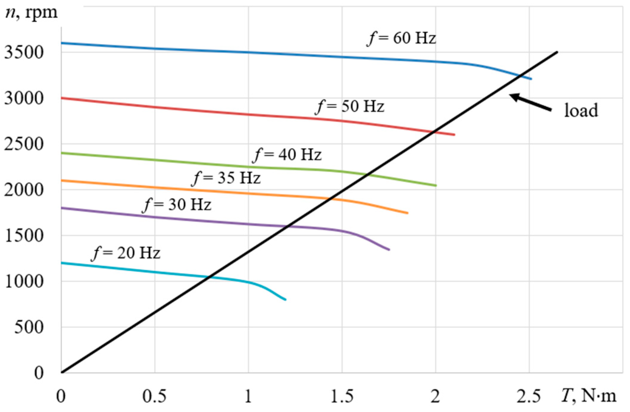
3. Experimental Study of Adjustable Asynchronous Electric Drive

To confirm the above theoretical provisions, experimental studies of a frequency-controlled asynchronous electric drive were carried out (Figure 1).
The asynchronous motor AIP71A2U3 is fed by the SEMITEACH-IGBT SKM50GB12T4 transistor frequency converter. The stator winding of the motor is star-connected. The mains voltage during the experiment was 380 V at a frequency of 50 Hz. The driver was controlled from the AVR-MT128 board with an integrated ATmega128 microcontroller. The program code implemented the frequency law for a constant moment U/f = const. The pulse width modulation frequency was set to 6 kHz.
When carrying out the experimental studies, the provisions given in [26] were fulfilled. We determined the powers and required coefficients by using the BORDO-421 device, and the oscillography of currents and voltages was carried out on both the grid and motor sides.
The oscillograms grid and motor sides are shown for an inverter frequency of 35 Hz and with a motor shaft load of 1.44 N m in Figure 2 and Figure 3, respectively.
Oscillograms look similar at other frequencies and loads. Their spectral analysis was carried out, and the coefficients of non-sinusoidal current and voltage distortions for the grid and motor sides were determined (Figure 3). From the FFT analysis diagram (fast Fourier transform) it can be seen that, in addition to the first (fundamental) harmonic, the harmonic composition contains higher harmonics, and the amplitudes of which vary depending on the harmonic number (Figure 3).
The power factors and the phase shift of the fundamental harmonic at the motor input are considered for a distorted system with non-sinusoidal distortions of currents and voltages (18). Distortion at the input of the drive is determined only by non-sinusoidal distortions of currents (19).
With the help of the program developed based on MATLAB, χED were found. The power factor χ on the motor side is determined in a similar way, i.e., χIM variable induction motor.
The power factors χ = P / S and the shift factor cos φ 1 = P / P 2 + Q 2 are calculated for both the grid and motor sides from the measured power values.
Table 1 shows the power components for the case under consideration.
The results of calculating the power factors and offset and harmonic distortion THDs, which were obtained by measuring instruments and by analyzing oscillograms using MATLAB, are presented in Table 2 and Table 3.
The drive had a linear load provided by a load generator (Figure 4). Experimentally, the control characteristics were obtained in the two above-described ways, which are the dependences of χED and cosφED (Figure 5), as well as χIM and cosφIM (Figure 6), on the rotational speed in a certain control range.
If the efficiency of the ASED is estimated for the entire specified control range, then χ and cosφ can be calculated as averaged values:
χ = 1 n 2 n 1 n 1 n 2 χ ( n i ) d n
cos φ = 1 n 2 n 1 n 1 n 2 cos φ ( n i ) d n
In this case, for the range 1050–3200 rpm, the averaged coefficients at the input of the frequency converter according to the measurements of devices are cos φED = 0.948 and χED = 0.558, and according to the processing of oscillograms, they are cos φED = 0.958 and χED = 0.511. At the motor input, the averaged coefficients have the following values according to the readings of the devices: cos φIM = 0.902 and χIM = 0.725; according to the processing of oscillograms, they are cos φIM = 0.86 and χIM = 0.682.
On the grid side, the values of the shift coefficients found by the two methods are close to 1, and the power factors χED found by the two methods differ insignificantly (χED = 0.558 for instruments and χED = 0.519 for the results of processing oscillograms). On the motor side, values of the shift coefficients are close to each other (cos φIM = 0.9 according to instruments and cos φIM = 0.852 according to the results of processing oscillograms), and the power factors χIM differ by 6.3% (χIM = 0.726 according to instruments and χIM = 0.678 according to the results of processing oscillograms).
If time operating load diagrams are known, i.e., operating time at each speed, due to the technological requirements for drive mechanisms, then the assessment of this range criterion must be performed considering the duration of operation at each control range point:
χ = i ( χ ( n i ) t n i ) i t n i ,
cos φ = i ( cos φ ( n i ) t n i ) i t n i .
where t n i is the time of motor operation at the corresponding speed and ni, i is the ordinal number of the tachogram stage.
If we assume that this motor rotates at 1700 rpm for 100 s, 2000 rpm for 300 s, and 3000 rpm for 200 s, then the coefficients according to the readings of the instruments (Figure 5 and Figure 6 blue lines) per cycle will be equal to χED = 0.564, χIM = 0.751, and cosφIM = 0.91. Similarly, we determine the coefficients when processing oscillograms (Figure 5 and Figure 6, red lines) as follows: χED = 0.506, χIM = 0.698, and cosφIM = 0.847. The cosφED values at the drive input are close to 1.

4. Conclusions

  • The analysis of electro-energetic and electromagnetic compatibility in distorted electrical systems requires considering not only the reactive power due to fundamental current phase shift and voltage but also other “inactive” powers, including reactive power due to the higher harmonic components. Any electrical system, especially a distorted one, requires determination of its electromagnetic and electro-energetic compatibility. Expressions of the power factor as a quantitative parameter of electro-energetic and electromagnetic compatibility for distorted systems are proposed.
  • The analysis and determination of the power components and power factor of a frequency-controlled asynchronous electric drive is carried out. The possibility of determining this coefficient in two ways is confirmed by using relatively inexpensive and generally available equipment, which is predominant in practical application.
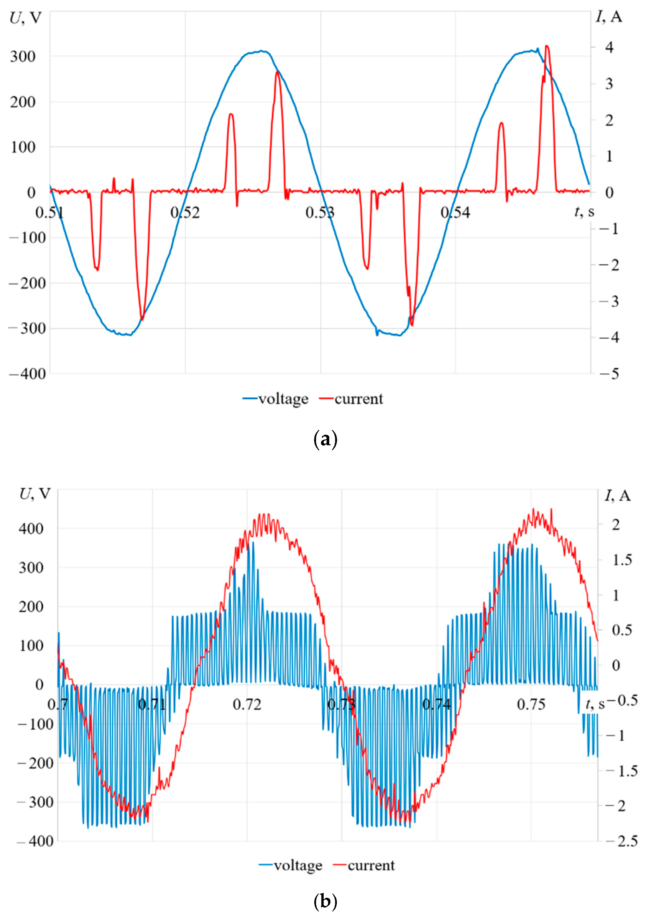
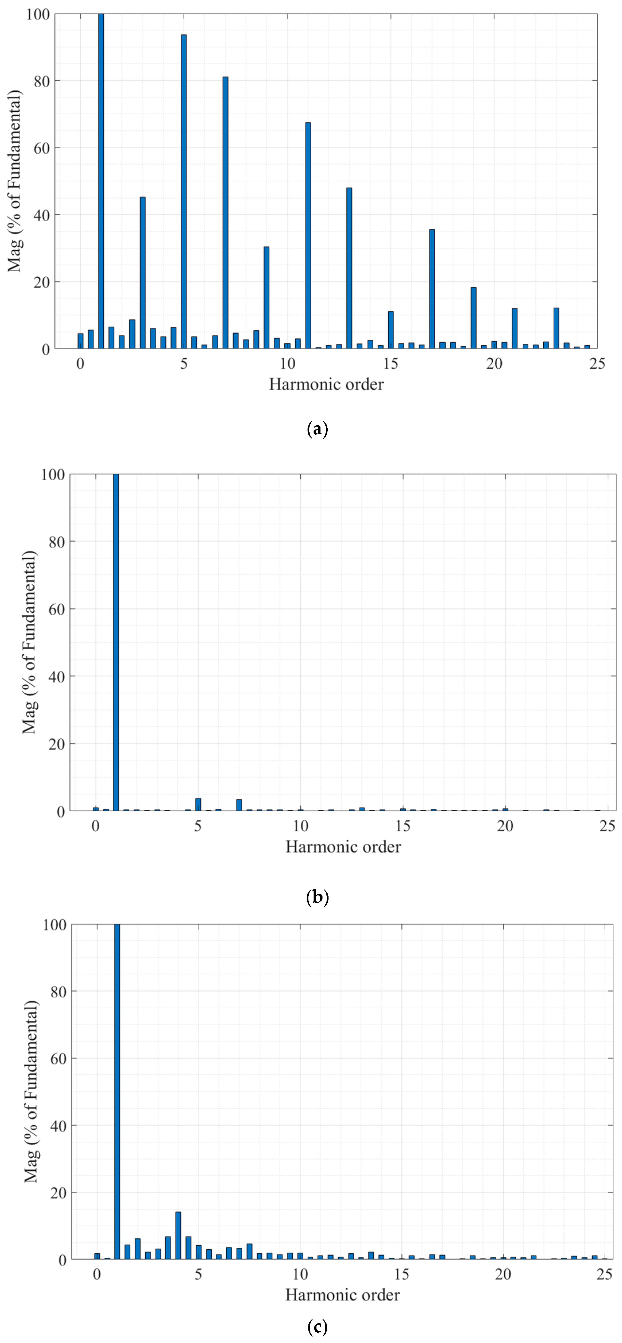
  • The balance of powers at different frequencies of voltages and currents of the electrical system of a controlled asynchronous electric drive is experimentally confirmed. The method for determining the coefficients from the results of oscillograms is more preferable. Measuring instruments are characterized by accuracy classes, the increase in which leads to a significant increase in their cost. There is a relative similarity of coefficient values determined from the measured power values and from the results of processing oscillograms using the coefficients of non-sinusoidal distortions. The shift coefficient on the grid side under consideration is practically equal to 1.
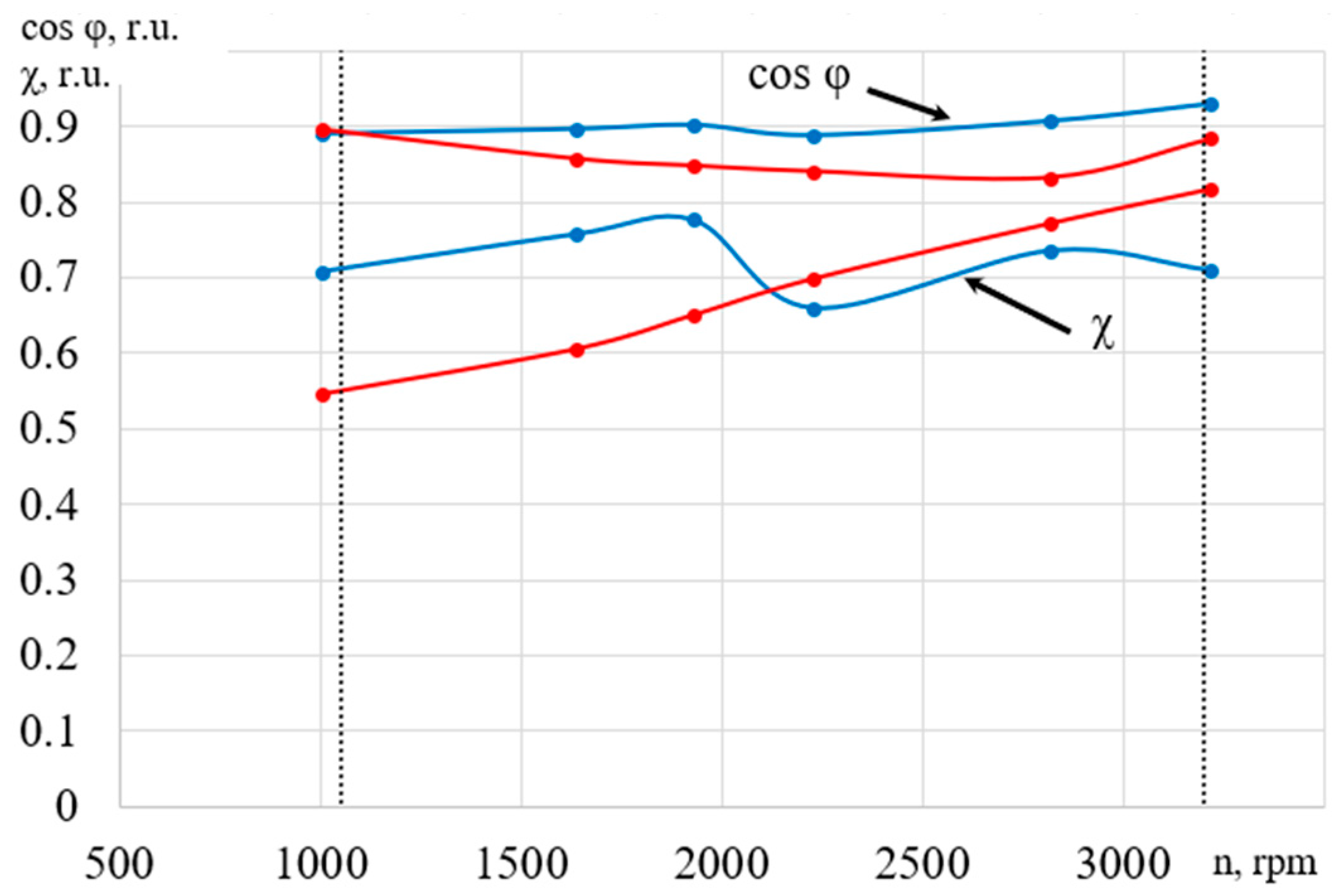
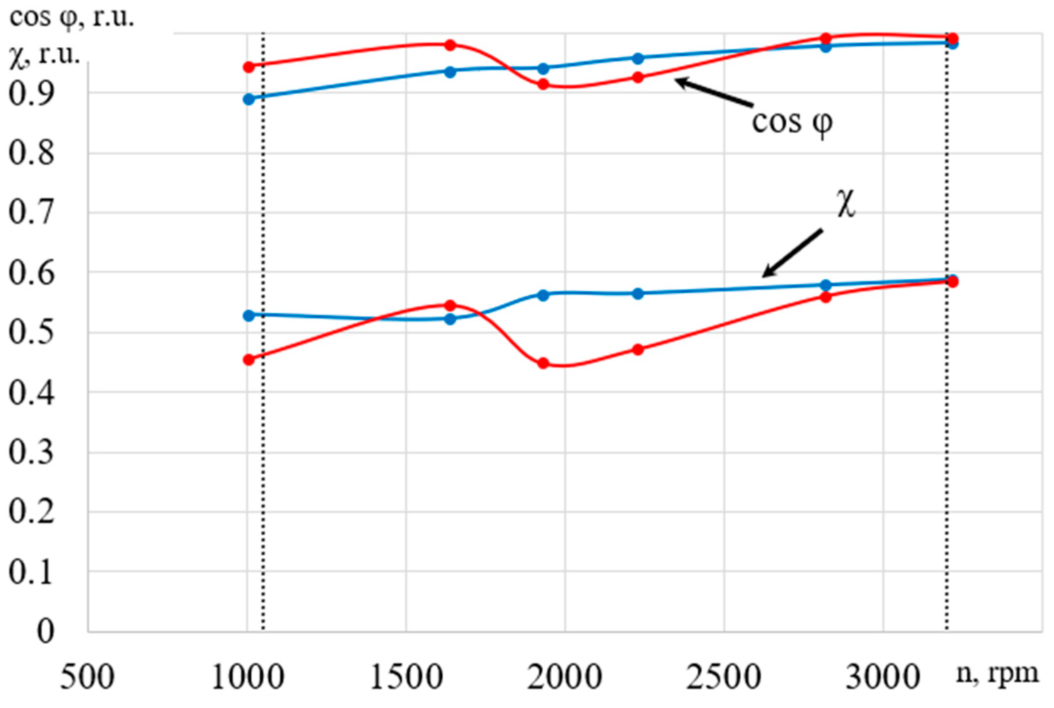
  • The power factor and phase shift factors of AM and ASED at a certain load are calculated as average over a certain range of speed or are determined by considering a given tachogram of speed changes. For the studies performed, the value of the power factors when operating on a certain tachogram based on the results of processing the oscillograms at the drive input and at the motor input are as follows: χED = 0.506, χIM = 0.698.

Author Contributions

Conceptualization, V.P. and J.P.; methodology, V.P.; software, J.P. and V.H.; validation, V.H., N.A. and Z.T.; formal analysis, J.P.; investigation, V.H.; resources, J.P.; data curation, V.H.; writing—original draft preparation, V.P.; writing—review and editing, V.P. and V.H.; visualization, N.A. and Z.T.; supervision, J.P.; project administration, V.P.; funding acquisition, J.P., N.A. and Z.T. All authors have read and agreed to the published version of the manuscript.

Funding

This research received no external funding.

Conflicts of Interest

The authors declare no conflict of interest.

Nomenclature

ε U —coefficients of voltage unbalance
ε I —coefficients of current unbalance
ε 0 U —coefficients of voltage lack of balance
ε 0 I —coefficients of current lack of balance
THD —total harmonic distortion
ASED —asynchronous electric drives
S M —apparent power
U A , U B , U C —effective values of phase voltages
I A , I B , I C —effective values of phase currents
U A 1 , U B 1 , U C 1 —effective values of the fundamental harmonics of phase voltages
I A 1 , I B 1 , I C 1 —effective values of the fundamental harmonics of phase currents
n U A n , n U B n , n U C n —total values of higher harmonics of voltages
n I A n , n I B n , n I C n —total values of higher harmonics of currents
D I —current distortion power
D U —voltage distortion power
D H —harmonic distortion power
U 0 , U 1 , U 2 —effective values of zero, direct and reverse voltage sequences
I 0 , I 1 , I 2 —effective values of zero, direct and reverse current sequences
P —active power
Q —reactive power
D —distortion power
S B —“pulsating” power
S 0 —“latent” power
S m —“modular” power
T H D I —total harmonic distortion of current
T H D U —total harmonic distortion of voltage
a —unity phasor a = ej120°
φ 1 —shift angle between the first harmonics of current and voltage
χ —power factor

References

  1. da Silva, R.P.B.; Quadros, R.; Shaker, H.R.; Carlos Pereira da Silva, L. Harmonic Interaction Effects on Power Quality and Electrical Energy Measurement System. In Proceedings of the 2019 International Symposium on Advanced Electrical and Communication Technologies (ISAECT), Rome, Italy, 27–29 November 2019. [Google Scholar]
  2. Petružela, M.; Blažek, V.; Vysocký, J. Analysis of Appliance Impact on Total Harmonic Distortion in Off-Grid System. Recent Advances in Electrical Engineering and Related Sciences: Theory and Application; Springer: Cham, Switzerland, 2020. [Google Scholar]
  3. Salman, M.; Haq, I.U.; Ahmad, T.; Ail, H.; Qamar, A.; Basit, A.; Khan, M.; Iqbal, J. Minimization of total harmonic distortions of cascaded H-bridge multilevel inverter by utilizing bio inspired AI algorithm. J. Wirel. Com. Netw. 2020, 66. [Google Scholar] [CrossRef] [Green Version]
  4. Manjesh Hasitha, K.; Bhoi, A.K.; Garg, A. Comparative Study of Harmonics and Total Harmonic Distortion of Five-Phase Inverter Drive with Five-Phase Multilevel Inverter Drive Using Simulink/MATLAB; Springer: Singapore, 2018. [Google Scholar]
  5. Benslimane, A.; Ouariachi, M.E.; Bouchnaif, J.; Grari, K. Analysis of the Electrical Unbalance Caused by the Moroccan High-Speed Railway in the High Voltage Power Grid for the Starting Horizon (2018) and the Horizon (2030). In Proceedings of the 1st International Conference on Electronic Engineering and Renewable Energy, Saidia, Morocco, 15–17 April 2018. [Google Scholar]
  6. Phan, A.T.; Wira, P.; Hermann, G. A dedicated state space for power system modeling and frequency and unbalance estimation. Evol. Syst. 2018, 9, 57–69. [Google Scholar] [CrossRef] [Green Version]
  7. Shi, H.; Zhuo, F.; Yi, H.; Geng, Z. Control strategy for microgrid under three-phase unbalance condition. J. Mod. Power Syst. Clean Energy 2016, 4, 94–102. [Google Scholar] [CrossRef] [Green Version]
  8. Mukund, R.P. Introduction to Electrical Power and Power Electronics; CRC Press Taylor & Francis Group: Boca Raton, FL, USA, 2013; p. 519. [Google Scholar]
  9. IEEE Std 1459-2010. IEEE Standart Definition for the Measurement of Electric Power Quantities Under Sinusoidal, Nonsinusoidal, Balanced, or Unbalanced Conditions; IEEE Power & Energy Society, IEEE-SA Standards Board; IEEE: Piscataway, NJ, USA, 2010. [Google Scholar]
  10. Melkebeek, J.A. Electrical Machines and Drives Fundamentals and Advanced Modelling; Springer: Cham, Switzerland, 2018; 740p. [Google Scholar]
  11. Stefanos, N.M. Power Electronics and Motor Drive Systems; Elsevier: London, UK, 2017; 987p. [Google Scholar]
  12. Pyrhonen, J.; Hrabovcova, R.V.; Semken, S. Electrical Machine Drives Control An Introduction; John Wiley & Sons Ltd.: Chichester, UK, 2016; 527p. [Google Scholar]
  13. Pivnyak, G.G.; Volkov, A.V. Modern Frequency-Controlled Asynchronous Electric Drives with Pulse-Width Modulation: Monograph; National Mining University: Dnepropetrovsk, Ukraine, 2006; 470p. [Google Scholar]
  14. IEC 60034-30-1. Rotating Electrical Machines. Part. 30-1. Efficiency Classes of Line Operated AC Motors (IE Code); International Electrotechnical Commission International Standard: Geneva, Switzerland, 2014; p. 54. [Google Scholar]
  15. IEC 60034-30-2. Rotating Electrical Machines. Part 30-2: Efficiency Classes of Variable Speed AC Motors (IE-Code); International Electrotechnical Commission International Standard: Geneva, Switzerland, 2016; p. 22. [Google Scholar]
  16. Mikitchenko, A.Y.; Shevchenko, A.N.; Biryukov, Y.A.; Shestakov, P.R. Efficiency of conversion of electrical energy in thyristor and transistor electric drives of excavators. Min. Inform. Anal. Bull. 2009, 12, 247–260. [Google Scholar]
  17. Andrienko, V.M. Determination of energy indicators of asynchronous motors when powered by static frequency converters. Electric. Eng. Electromech. 2010, 3, 5–7. [Google Scholar]
  18. Vasiliev, B.Y. Electric drive. Power engineering of an electric drive: A Textbook; SOLON-Press: Carmignano di Brenta, Italy, 2015; 268p. [Google Scholar]
  19. Kavitha, G.; Mohammed Rafeequdin, I. Hybrid Techniques for Reducing Total Harmonic Distortion in a Inverter-Fed Permanent Magnet—SM Drive System; Springer: Singapore, 2017. [Google Scholar]
  20. Adekitan, A.I. A New Definition of Voltage Unbalance Using Supply Phase Shift. J. Control. Autom. Electr. Syst. 2020, 31, 718–725. [Google Scholar] [CrossRef]
  21. Guasch-Pesquer, L.; Jaramillo-Matta, A.A.; Gonzalez-Molina, F.; Garcia-Rios, S. Analysis of Current Unbalance and Torque Ripple Generated by Simulations of Voltage Unbalance in Induction Motors. In Proceedings of the WEA 2017 Communications in Computer and Information Science, Cartagena, Colombia, 27–29 September 2017. [Google Scholar]
  22. Firago, B.I.; Palyavchik, L.B. The theory of electric drive. In Techno Perspective; Vysheysha Shkola: Minsk, Belarus, 2007; 585p. [Google Scholar]
  23. Petrushin, V.S.; Yenoktaiev, R.N.; Shestakov, O.I.; Prokopenko, N.S. Allowance for loss of the higher harmonic in the controlled induction motors. In Bulletin of NTU “KhPI”; Series: “Electric Machines and Electromechanical Energy Conversion”; NTU “KhPI”: Kharkiv, Ukraine, 2017; Volume 1, pp. 101–105. [Google Scholar]
  24. IEC/TS 60034-17:2006. Rotating Electrical Machines—Part 17: Cage Induction Motors When Fed from Converters—Application Guide; International Electrotechnical Commission International Standard: Geneva, Switzerland, 2006. [Google Scholar]
  25. IEC/TS 60034-25:2007. Rotating Electrical Machines—Part 25: Guidance for the Design and Performance of a.c. Motors Specifically Designed for Converter Supply; International Electrotechnical Commission International Standard: Geneva, Switzerland, 2007. [Google Scholar]
  26. IEC 60034-2-3. Rotating Electrical Machines. Part 2–3. Specific Test Methods for Determining Losses and Efficiency of Converter-Fed AC Induction Motors. Available online: https://files.stroyinf.ru/Data/619/61981.pdf (accessed on 21 May 2021).
Figure 1. General view of the experimental stand with an adjustable asynchronous electric drive.
Electronics 10 01676 g001
Figure 2. Oscillograms of phase voltages and currents grid side (a) and motor side (b) at a frequency of 35 Hz.
Electronics 10 01676 g002
Figure 3. Spectral analysis of the grid side current (a), motor current (b) and motor voltage (c).
Electronics 10 01676 g003
Figure 4. Family of the mechanical characteristics of the motor at different frequencies of the supply voltage and the dependence of the load.
Electronics 10 01676 g004
Figure 5. Dependences of the power factors χ and the shift cos φ on the rotational speed on the grid side, where red is the processing of oscillograms and blue is the measurements by devices.
Electronics 10 01676 g005
Figure 6. Dependences of the power factors χ and the shift cos φ on the rotational speed at the motor input, where red is the processing of oscillograms and blue is the measurements by instruments.
Electronics 10 01676 g006
Table 1. Power balance at 35 Hz inverter frequency and 1.44 Nm load according to oscillogram readings.
S, V·AP, WQ, VArD, VAr
Grid side921395175814
Motor side470338210246
Table 2. Calculation results of power factor and offset and harmonic distortion (grid side) at an inverter frequency of 35 Hz and a load of 1.44 N m.
ParameterMeasurement Method
DevicesOscillograms
χED0.5630.45
cosφ1 ED0.9420.914
THDI ED1.772
Table 3. Calculation results of power factors and offset and harmonic distortion (motor side) at an inverter frequency of 35 Hz and a load of 1.44 N m.
ParameterMeasurement Method
DevicesOscillograms
χIM0.7770.651
cosφ1 IM0.9020.848
THDI IM0.0826
THDU IM0.828
Publisher’s Note: MDPI stays neutral with regard to jurisdictional claims in published maps and institutional affiliations.

