Abstract
This technical paper proposes a new waveform combining the low-rate and high-rate data streams to detect the region-of-interest signal in a high-mobility environment using optical camera communication. The proposed technique augments the bit rate of the low-rate stream; consequently, the link setup time is reduced and the requirement of low frame rate camera is eliminated. Additionally, both the low-rate and high-rate data streams in the proposed bi-level pulse position modulation are decoded with a unique adaptive thresholding mechanism with a high frame rate camera. We also propose a vehicle localization scheme to assist the drivers in maintaining a safe following distance that can significantly reduce the frequency of accidents. Moreover, two neural networks are proposed to detect the light-emitting diodes (LEDs) for localization and communication, and to estimate the road curvature from different rear LED shapes of the forwarding vehicle, respectively. The system is implemented, and its performance is analyzed in Python 3.7. The implementation results show that the proposed system is able to achieve 75% localization accuracy, a 150 bps low-rate stream, and a 600 bps high-rate stream over a range of 25 m with a commercial 30 fps camera.
1. Introduction
Vehicle navigation systems first drew attention in the late 1960s in the United States. The related primary goals included reducing highway congestion, increasing fuel efficiency, guiding routes, avoiding vehicle collisions, and collecting tolls electronically [1]. Nowadays, advanced driver-assistance systems are being extensively researched to reduce the number of casualties due to road accidents. Vehicle positioning and vehicle to vehicle (V2V) communication have immense potential to reduce the number of road accidents, making it possible to save the lives of a significant number of people by providing nearby vehicular position information to drivers. In particular, an intelligent transportation system requires precise vehicle positioning to ensure a safe braking distance from surrounding vehicles. The selection of appropriate technology is a challenging task as the vehicular density is high in metropolitan areas. Using radio frequency (RF)-based technologies, the system performance is expected to degrade owing to the huge amount of electromagnetic interference. Moreover, regular long-term involvement with RF can lead to adverse effects on drivers’ health [2,3,4]. With the exponential growth of connected devices in 5G, which is supposed to become a more complex scenario in 6G, a visible light spectrum with bandwidth over thousands of times that of RF has attracted much interest from researchers.
Nowadays, most vehicles are equipped with one or more cameras to assist in driving and parking, and daytime-running lights to draw the attention of other road users. The main objective is to ensure safety and a better driving experience by providing views of blind spots. Optical camera communication (OCC) can take advantage of the built-in light-emitting diodes (LEDs) as a transmitter and the camera as a receiver [5,6]. Other key advantages of OCC technology include nearly interference-free communication and an unlicensed spectrum that can be used as a complement for the nearly saturated RF spectrum [7]. In a V2V communication scenario, the signal-to-noise ratio (SNR) is high, as the LEDs used for lighting have very high luminance. It offers a very strong line-of-sight (LOS) link set up at a long distance with a low bit error rate. Additionally, the effect of sunlight, a major challenge for other optical wireless communication systems in outdoor environments, can be effectively eliminated. Despite the high-speed switching capability of LEDs, the data rate of OCC systems is predominantly limited by the camera frame rate. Therefore, the significant advantages of OCC are often overshadowed by its low data rate. Researchers have already proposed a high-speed camera and multiple-input multiple-output technique [8,9,10] using an LED array to increase the data rate to one suitable for sensor data monitoring [11], patient monitoring [12], vehicular communication [13], and other low-rate indoor and outdoor applications [14,15].
At present, the global positioning system is considered one of the most effective solutions for automobile navigation systems. It requires signals from a minimum of four satellites for a particular time to determine its three-dimensional (3D) location information. However, it faces significant challenges when the high-frequency signal is blocked by solid objects, such as terrains, subways, towering buildings, and trees. Additionally, it provides self-localization information but cannot measure inter-vehicle distance [1].
Radio detection and ranging (RADAR) is another potential candidate for inter-vehicle distance measurement that suffers from low localization estimation accuracy in the lateral direction, as it measures the angle of an object from the phase difference of multiple antennas. Frequency-modulated continuous-wave RADAR measures the distance and velocity of the forwarding vehicles (FWV) by transmitting a continuous-wave and analyzing the frequency variation between the transmitted and received waves [16]. However, as vehicle corner part detection is impossible with RADAR, sensor fusion techniques are considered a viable solution. Camera and RADAR sensor fusion has recently been proposed for the improvement of individual camera or RADAR-based systems [17]. Here, a camera is used for the corner part detection of vehicles, and RADAR is used for the distance estimation. Still, this system suffers from considerable inaccuracy. Moreover, no V2V and vehicle to everything (V2X) communications link can be established via the camera for the deployment of the internet of vehicles (IoV). Vehicular ad hoc networks systems are used for vehicle localization and direct communication or through roadside units using RF. It involves the challenges in the high vehicular density areas owing to the interference from various signal sources [18].
To overcome the limitations of RF systems and support the massive connectivity of the IoV, researchers have proposed a multifunctional OCC capable of imaging, vehicular localization, and communication. Tanvir et al. have introduced OCC-integrated streetlamps to determine the position of FWVs to cope with the challenges associated with high-mobility transmitters and receivers [19]. However, they have not considered the diversity in the design of the taillights because this depends on the manufacturer. Therefore, the achieved system accuracy (10–20 cm) will eventually decrease in practical cases.
The position of the FWVs can also be measured from the rear LEDs using a backpropagation neural network with the help of two cameras [20]. However, in metropolitan areas, only one LED may be visible in the captured image owing to lots of traffic that challenge is addressed in [21]. Additionally, the distance measurement error caused by commercial low-resolution cameras is significantly reduced by splitting one pixel into multiple regions. However, no light was shed on the IoV.
In our proposed scheme, OCC is applied to transmit a vehicle’s identity (ID) to the following vehicles (FLVs) so that they can distinguish between the different transmitters. The FWVs’ location information is calculated from the projected LED coordinates on the image sensor (IS), and the moving direction of the FWVs and road curvature are determined from the rear LED shapes on the IS using a neural network (NN). Moreover, a novel modulation scheme, called bi-level pulse position modulation (BPPM), is proposed for optical vehicular communication whereby the same information is transmitted from both LEDs and decoded using a single camera. Thus, vehicle localization information can be obtained even if one rear LED is obscured with the necessary information obtained from another LED by virtually creating its coordinates. The main contributions of our work are as follows:
- A novel modulation technique is proposed for V2X communications wherein both low-rate and high-rate streams can be simultaneously decoded from the light intensities. This technique successfully converts two camera-based vehicular OCC systems into one;
- A vehicle localization scheme is proposed that can determine the inter-vehicular distance and angle from the rear LED shapes of the FWVs using a single camera. It can localize an FWV of any size and any taillight design via the assistance of the OCC system;
- To reduce accidents at road bends, a road curvature estimation technique from the rear LED shapes of the FWVs is implemented. A mathematical approach using OCC as well as a more accurate NN-based approach is explained in the following sections.
In this study, first, we formulated the localization and road curvature estimation problems along with a new modulation scheme to improve the OCC performance. Then, we implemented the transmitter and receiver, and subsequently, we decoded the information sent from the LEDs. Simultaneously, we implemented the localization and road curvature measurement algorithms. The performance of the proposed algorithms and the data-decoding mechanism is then evaluated in Python environment. The rest of the article is organized as follows: The system overview is briefly explained in Section 2. Section 3 illustrates the proposed system, and the performance of the system is discussed in Section 4. Finally, bottom lines are drawn in Section 5.
2. System Overview
The proposed OCC based vehicle localization technique is shown in Figure 1. The taillights of every vehicle broadcast the vehicle ID and other information to other FLVs. A high-speed camera is mounted on the front side of every vehicle as a receiver to capture the taillights of the FWVs, which are detected using deep learning among the numerous interfering light sources in the road. Both localization and necessary information can be received from the blinking patterns of the LEDs. The modulation frequency is maintained at over 100 Hz to make the blinking pattern indistinguishable from that of human eyes [22].
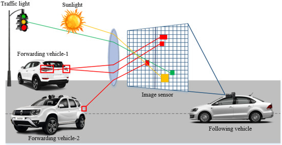
Figure 1.
OCC-based vehicle localization scenario from the rear LED shapes of the vehicles.
The IS of the FLVs can receive data from multiple vehicles concurrently owing to its spatial analysis capability. Additionally, up-to-date advancements in image processing techniques can efficiently eliminate the effect of noises from sunlight and streetlights. Therefore, a highly reliable LOS link can be established. In real-world scenarios, numerous vehicles will be on the road, so identification of every vehicle is necessary. Thus, OCC-integrated vehicles transmit a low-rate stream as their ID apart from a high-rate communication data stream so that they can be distinguished from other vehicles on the basis of their unique ID. This technique reduces the extremely low-rate OCC link setup time in a high-mobility environment. As the position of the FWVs and FLVs changes quickly as a result of their high-mobility, the camera of the latter is considered the reference point of the coordinate system for the distance estimation between the FWVs and FLVs.
Three general on-road scenarios are considered here, i.e., the vertical distance between FWVs and FLVs can increase or decrease, the FWVs can move laterally, and the FWVs can turn either left or right. In the first two cases, both rear LED sizes remain equal, but in the last case, they become unequal. The size of the LEDs in the captured image decreases with an increase in distance, whereas the coordinates of the LEDs varies with the lateral movement of the FWVs, FLVs, or both, as shown in Figure 2a–c. This distance can be calculated with the variation in LED size; after a certain distance, the LEDs become too small to be detectable. This system will work provided that the projected LED image on the IS covers a minimum of a one-unit pixel area. This system can also be integrated with an RF system in such a way that when the LED size falls below the threshold level, it will switch to the RF network. However, vehicles at a large distance impose a smaller threat than closer vehicles do. Thus, a hybrid system for large distance estimation is considered superfluous.
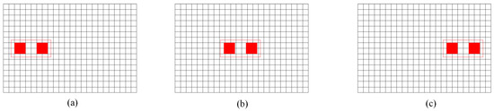
Figure 2.
Alternation of LED coordinates of an FWV moving from right to left with respect to the FLV on an image sensor. (a) FWV is at the right side of the FLV. (b) FWV is straight with respect to FLV. (c) FWV is at the left side of FLV.
3. Proposed Scheme
3.1. Proposed OCC System for V2V Scenario
Figure 3 shows the complete architecture of the proposed system. In general, we used two different low-rate and high-rate data streams transmitted from each of the rear LEDs for the source identification and data transmission, respectively. A combination of both streams, i.e., a hybrid stream, propagated through the optical channel and was received in the IS. Motion blur was expected in the captured images owing to the vehicles’ high-mobility. On the receiver side, the region-of-interest (RoI) was detected in the captured images using an NN, and the data decoding and localization mechanisms were executed eventually. As the intensity of the LED in the camera sensor varied with the distance between vehicles, the detection threshold of the high-rate stream was kept constant, whereas the threshold for the low-rate stream was dynamically adjusted with the help of the high and low-level amplitudes of the high-rate stream. Here, the receiver camera had to be a global shutter type since this performs better than a rolling shutter camera in a high-mobility environment. It can capture the hybrid waveform that is decoded to retrieve the high-rate and low-rate streams simultaneously. As a rolling shutter camera scans the pixels row by row, significant distortion may occur owing to the high-mobility, whereas a global shutter camera reads all pixels at the same time to detect all LED states simultaneously, showing superior performance in high-mobility environments. An explanation of the individual subsystems is provided in the following sections.
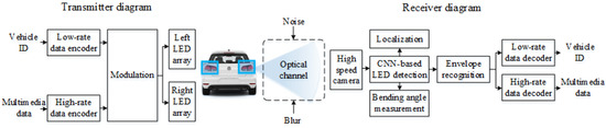
Figure 3.
Proposed OCC architecture for vehicle localization and communication.
3.2. Transmitter
In general, LEDs that transmit visible light are primarily used as vehicle headlights or backlights, which are mainly utilized as the transmitter in OCC. An LED array might be used to increase the data transmission rate, but as the distance increases, it becomes difficult for the camera to recognize and classify each LED. Therefore, an LED array can be considered for short distance data transmission and it can be segmented into several groups for medium distances [23]. For long distances, the LED array can be considered as a single LED.
Two types of vehicular data, i.e., the vehicular ID and multimedia data, were encoded as the low-rate and high-rate data streams and simultaneously transmitted using a single LED. The vehicular ID was used to distinguish between different vehicles, whereas the multimedia data were transmitted after establishing a connection with a specific vehicle. To modulate both data streams in a single LED, we proposed BPPM utilizing multiple power levels of the LED. Data decoding using different intensity levels is challenging, so we considered three intensity levels, i.e., high, intermediate, and low, for feasibility.
According to the PHY IV mode of IEEE 802.15.7-2018, a modulation technique for vehicular communication should offer detection and tracking of several transmitters, as well as communication data. The OCC transmitter is designed in such a way that it can transmit the high-rate and low-rate data streams together as a hybrid waveform for the successful establishment of a communication link. Existing schemes standardized in IEEE 802.15.7-2018, i.e., twinkle variable pulse position modulation (Twinkle-VPPM) and hybrid spatial phase-shift keying (HS-PSK) are designed so that they transmit undersampled frequency-shift on–off keying (UFSOOK) and spatial 2-PSK (S2-PSK) as low-rate data streams, and VPPM, and dimmable spatial 8-PSK (DS8-PSK) as high-rate streams, respectively. However, HS-PSK and Twinkle-VPPM require two cameras to receive the data streams. In Twinkle-VPPM, a low-rate UFSOOK stream is generated by varying the pulse width of the high-rate VPPM stream. On the other hand, in HS-PSK, S2-PSK is generated by varying the intensity of DS8-PSK among seven possible dimming levels. The low-rate and high-rate streams are decoded using a low-speed and a high-speed camera, respectively. For DS8-PSK, a reference LED group consisting of eight LEDs is required to decode every 3 bits of data [13]. Consequently, the number of bits transmitted per image frame is lower than the number of LEDs in the LED array. Additionally, one of the rear LEDs of the vehicle can go out of the camera’s field of view or become non-LOS owing to blockage. These challenges are overcome in the proposed BPPM scheme by transmitting same hybrid waveform from each of the rear LEDs.
As shown in Figure 4, each of the rear LEDs transmitted the same information concurrently in our proposed scheme. High-speed data streams were modulated with a PPM scheme, and 1 and 0 bits were represented by a pulse of the same amplitude at the opposite end of the bit period. Low-speed data streams were transmitted by modulating the pulse amplitudes of the high-speed streams using two different intensity levels. For Level 1, the amplitudes of the pulses were assigned to the highest level, and for Level 0, the amplitudes of the pulses were assigned to an intermediate level between the high and low levels. Two threshold values, i.e., and , were used to decode the low-rate and high-rate streams, respectively. To remediate the flickering effect observed by the human eye, the chosen modulation frequency was above 100 Hz. It is worth noting that the human eye perceives the average level of intensity transmitted by an LED. Therefore, the average intensity level must be kept constant for comfortable driving. Consequently, we increased the amplitude of the PPM signal and reduced the duty cycle to keep the average intensity level constant. Furthermore, the bit period of the low-rate data stream was chosen so that the modulation frequency did not fall below 100 Hz.
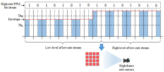
Figure 4.
Proposed BPPM scheme for optical vehicular communication using a single camera.
3.3. Receiver
3.3.1. LED Detection
In the V2X environment, different types of LEDs are deployed for various purposes, such as signaling, indicating, decoration, digital signage, and data transmission. For data transmission, OCC is a well-known technique wherein the LEDs serve as a transmitter and the camera as a receiver. On the receiver side, different techniques are applied to extract data from the corresponding LED images. Before the data processing, the location of the LEDs needs to be identified using the RoI and NN-based detection technique. In a vehicular scenario, the LEDs size and shape are not constant and may vary with distance, relative speed, road curvature, etc. In such cases, RoI detection is performed by adjusting the aspect ratio of the light intensity that contains different features. This technique is mainly performed using region-based active contour approaches that represent the segmentation of the images into defined regions. Again, RoI signaling is an OCC mode that has been proposed in IEEE 802.15.7-2018 PHY IV. Therefore, the transmitter needs to send the short-length vehicle ID and long-length communication data simultaneously. To start, the low-rate stream is extracted from the composite waveform to decode the vehicle ID; then, the other information associated with the high-rate stream is obtained from a recognized transmitter. However, one of the key performance indexes, time complexity is suboptimal in this scenario because no information can be decoded during the link setup time.
In a mobile scenario, the IS experiences blur, and the shape of the light source changes, which cannot be solved using the RoI-based detection technique. Therefore, here, we used an NN-based technique for LED detection based on the training data. Two NNs were designed here, one to detect and track vehicular LEDs and the other to estimate the road curvature (Section 3.3.3).
We used a convolutional NN (CNN), which is considered a powerful tool for image and video processing, pattern and speech recognition, and natural language processing. A CNN extracts features and learns automatically from the input images. It analyzes a small number of pixels instead of all the pixels for LED detection, thus reducing both the computational time and complexity. It has several layers, namely, the convolutional layer, pooling layer, and fully connected layer. The convolutional layer plays a key role in producing proposed regions and feature maps, whereas the pooling layer’s purpose is to downsample the images while keeping all the features. Repetition of these blocks can be used to design deep NNs. The fully connected layer is generally the final layer of the architecture. The output shows that the class of the input image that is shown in Figure 5. Here, 1000 images of different road curvatures labeled with different angles were used to train the model. We used of the total images for the training with the help of Darknet for our implementation using OpenCV in Python. To train the weight value, we used yolov3.weights with yolov3_training.cfg and name.txt.
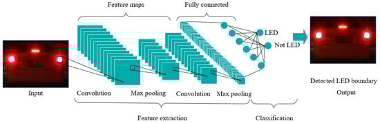
Figure 5.
A CNN-based vehicular taillight detection scheme.
3.3.2. Vehicle Localization
The distance and angular position of the FWVs were determined via the Cartesian or polar coordinates of the LEDs on the IS. In this regard, the IS was envisioned as a two-dimensional (2D) coordinate system wherein the 3D camera coordinates were converted into a 2D matrix or vector. The LED coordinates were continuously changing over time, making precise distance measurement challenging. Thus, the shapes of the rear LEDs were compared to determine the direction of movement of the FWVs. If the FWVs were moving straight, the size of the rear LEDs on the IS in the FLV’s front camera was the same. The FWVs turning to the left or right could be detected from the rear LED shapes owing to their dissimilar appearance on the IS. The projected image of the left LED appeared larger compared with that of the right LED when the FWVs turned left, and vice versa. In particular, after the OCC link was established, the distance between the two rear LEDs was forwarded from the FWVs to the FLVs. If the distance of the LED and its projected image from the camera lens was O and o, respectively, the general lens equation for an IS with a focal length of f was presented as follows
The magnification factor is used to relate the ratio of the projected area of the LED on the IS, , and the actual size of the LED, , with the ratio of the distance of the LED from the lens, D, and the distance of the projected image on the IS, d, from the lens. It is written as follows
If the condition is satisfied, the preceding two equations are combined to measure the distance (D) directly as
where a is the unit pixel length and is the number of pixels of the projected image on the IS. The absolute value of all parameters had to be taken to avoid the negative value of distance. Therefore, the distance of the vehicle was directly proportional to the square root of the actual LED size and inversely proportional to the square root of the number of pixels of the projected image on the IS.
Measurement of the distance from FLV to FWV is challenging and often accompanied by a significant amount of inaccuracy owing to the vehicles’ high-mobility. Thus, the distance measurement of an FWV from any fixed point is impossible. Therefore, in this work, the FWV distance was measured from the IS of the FLV. Cartesian, polar, or any other coordinate systems could be used for the localization. After detecting the rear LEDs of the FWV, the distance between the FLV and FWV was calculated via photogrammetry. The projected image areas of the rear LEDs of the FWV were decreased as the distance from the FLV was increased. When the front vehicle was on the right side of the FLV and the distances of the left and right rear LEDs of the FWV from the FLV were and , respectively, Equations (6) and (7) could be written according to the Pythagorean theorem as
where is the distance between the left and right rear LEDs of the FWV, and C is the horizontal distance of the nearest rear LED of the FWV perpendicular to the vertical distance, which could be expressed as
Subsequently, the perpendicular distance (D) was calculated using Equations (6)–(8).
Two axes were used to find the center of the plane to determine the lateral position of the FWVs with respect to the FLVs. When the front vehicle was on the left side of the FLV, the distance was calculated as follows
When the front vehicle is on the same line as the FLV, the distance was calculated as
Then, the angular distance of the left and right LEDs, and the center of the vehicle were calculated as
The overall algorithm to localize the FWVs is shown in Algorithm 1.
| Algorithm 1 Vehicle localization and communication scheme. |
| Input: captured images, training.weights, classes.txt, testing.cfg. Output: , , .
|
3.3.3. Road Curvature Estimation
Using the actual vehicle size along with the determined direction obtained using OCC, the amount of road curvature was determined from the rear LED shapes of the FWV. The rear LED shapes of the FWV projected on the IS of the FLV in different directions are shown in Figure 6. When the FWV turned left with respect to the FLV, the distance between the two rear LEDs and the size of the right rear LED in the IS appeared to decrease, as shown in Figure 6a. The larger the road curvature, the smaller the size of the right rear LED. The projected image of the left LED experienced a similar situation when the FWV turned right, as shown in Figure 6c. When the FWV moved straight with respect to the FLV, the size of the both LEDs appeared to be same which is depicted in Figure 6b. The procedure for determining the road curvature is presented in Figure 7.
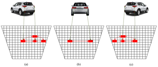
Figure 6.
Change of rear LED shapes when the forwarding vehicle (a) turns left, (b) moves straight, and (c) turns right.
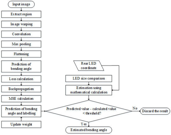
Figure 7.
Flowchart of detection and measurement of road bending angle from LED shapes.
A CNN with two hidden layers was used to classify the images at different angular conditions. At first, the NN was trained with 5000 images with their corresponding road curvature angles. The dimensions of the input and output vectors were 5000 × 6 and 5000 × 1, respectively, i.e., the dimension of the dataset was 5000 × 7. Numerous light sources can exist in an image, including several backlights of on-road and off-road vehicles. If all pixels were given as input to the NN, the time complexity of the network would be enormously high. Therefore, the RoI was detected, and the interfering light sources were removed. Next, each pair of vehicular taillights was extracted as individual warped images. Then, a 4 × 4 convolutional filter was utilized to extract the features, whereas max pooling with a 2 × 2 filter further reduced the size of the warped images, preserving all features. This pooled feature map was flattened into one column, which was fed as the input to the NN.
In this work, the non-linear softmax function was used, as the most attention was paid to the convergence efficiency. As a result, the penalty was imposed on the classification accuracy of the training data rather than the discriminative power of the learned bending angle representations. Thus, the filter weights were updated through the backpropagation mechanism to set the optimal filter value for testing purposes. The images were labeled with the estimated bending angle, and the mean square error (MSE) was calculated in the testing step.
The road curvature could also be estimated trigonometrically. First, the coordinates of the LEDs were taken from the warped images, as mentioned above. Second, the distance per unit pixel was calculated with the prior knowledge of the distance between the rear LED pair obtained using OCC. When the FWV entered a curve, its direction was determined from the dissimilar shapes of the rear LED pair, and it seemed that the distance between the LEDs shrunk even though it actually remained constant. Third, the apparent distance between the LEDs was estimated with the previously calculated distance per pixel. Finally, by analyzing the hypothetical triangle formed, as shown in Figure 8a,b, the bending angle was calculated using the cosine function as follows
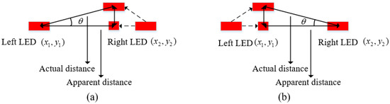
Figure 8.
Hypothetical triangle for calculation of bending angle when the FWV turns (a) left and (b) right.
This process was valid until the LEDs did not overlap in the IS.
4. Results
We constructed a vehicle taillight prototype to assess the performance of our proposed system economically. The implementation parameters are listed in Table 1. The taillight pair was randomly moved at three different orientations, i.e., left, right, and straight; a set of implementation results is shown in Figure 9. The implementation results were verified by measuring the deviation with the actual values. The deviations were under the tolerance limit, which was set at .

Table 1.
Implementation parameters.
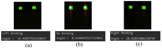
Figure 9.
The projected rear LED image of FWV on the image sensor of FLV when it enters into a road that (a) curves in the left direction, (b) goes straight, and (c) curves in the right direction.
Figure 10 shows that the MSE in angle calculation decreased as the number of iterations increased. The iteration rate was varied up to 1200 iterations to select the optimum learning rate. The learning rate changed very slowly after iteration 700 and became nearly constant around iteration 1100. The learning rate was set at 0.001.
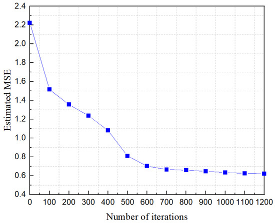
Figure 10.
Reduction of error in angle calculation with the number of iterations.
The distance estimation accuracy was also determined which is shown in Figure 11. The distance of the FWV from the FLV was estimated via necessary experiments and training with the previously recorded data. For identical rear LEDs of an FWV, the detected contour size would increase if an FLV approached it, and vice versa. Therefore, an experiment was performed to record the LED contour area and the corresponding distances. For instance, a circular LED with a diameter of 3 mm was considered, and 500 samples were recorded within a range of 50 m. The system was tested in a scenario, and the distance was measured by comparing it with the dataset. The accuracy decreased sharply when the distance increased to over 20 m because the change in the detected LED contour size decreased after a certain distance was reached. The inaccuracy of detecting the pixel coordinates increased as the distance increased. As a result, the estimation accuracy of the low-resolution camera was unsatisfactory at a large distance. At a long distance, a better approximation can be achieved by diving the pixels into n segments or using a high-resolution camera.
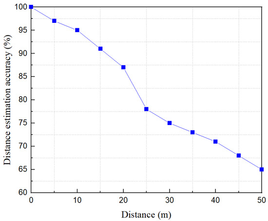
Figure 11.
Estimation of distance measurement accuracy.
The OCC data were decoded from the light intensity received in the IS. In the case of a single LED transmitter, bright and dark stripes were generated according to the ON and OFF states of the LED owing to the camera’s rolling shutter effect. In our work, two types of bright stripes were generated, one for the high-power-level signal and the other for the low-power-level signal. The stripe patterns received in the IS are shown in Figure 12. The thickness of the stripes was dependent on the frequency of the modulated signal. The high power signals created a brighter stripe than did the low power signals in the IS. Every two consecutive high-frequency data bits’ amplitude was modulated according to the low-rate stream. Two different threshold levels (i.e., and ) were used to retrieve the transmitted data from the stripe pattern. Moreover, was compared with every bit to detect the high-rate data stream, and was compared with the intensity level of every two consecutive data bits to detect the low-rate stream.
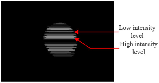
Figure 12.
Received stripe patterns in the camera receiver.
As the light intensity varies with the variation of distance, the data rate remarkably depends on the inter-vehicular distance. To illustrate the effect of transmitted power on data rate, data rate is plotted against distance at two different power levels (i.e., 2 and 5 dB) in Figure 13. The data rate of the high-rate stream of 2 dB power level falls below 200 bps whereas it is approximately 600 bps for 5 dB power level at 25 m distance. The difference in data rate between low-rate streams was also maintained at approximately 50 bps up to 30 m which is a crucial factor in determining link setup time in a high mobility environment. Additionally, the OCC channel capacity was strongly dependent on the camera frame rate, which could be determined from Shanon’s channel capacity formula [24].
where , W, and represent the photo-receptor sampling rate in frames per second, number of attainable pixels per frame, and signal-to-interference-plus-noise ratio for every pixel, respectively.
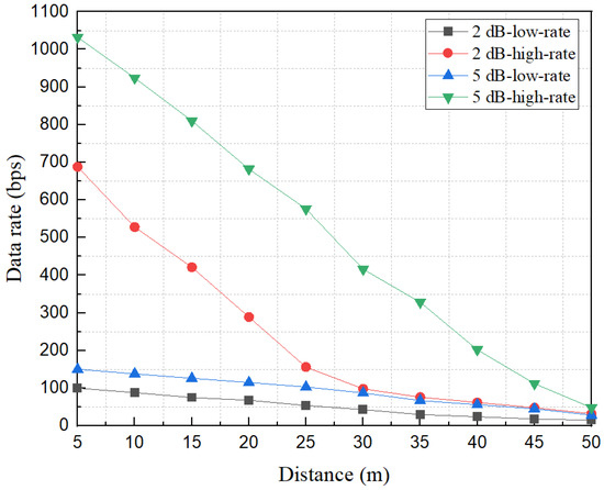
Figure 13.
Variation of data-rate with distance at 2 dB and 5 dB transmitter power level.
The optical power received depended on both the distance between the transmitter and receiver and the difference between the two threshold levels that played a vital role in the system performance. The bit-error-rate (BER) performance of the proposed system versus the difference between the two threshold levels while keeping the value constant is shown in Figure 14. When the difference between the two levels increased, the probability of bit corruption decreased, which resulted in a sharp fall of the BER. However, the selection of the optimum threshold value should consider the required illumination level and sensitivity of the IS. The BER of our proposed scheme was deter-mined with the following equation
where , , and refers to the threshold value, received power, and noise power spectral density. b is equal to the transmitted bit value and l is the transmitted bit sequence length.
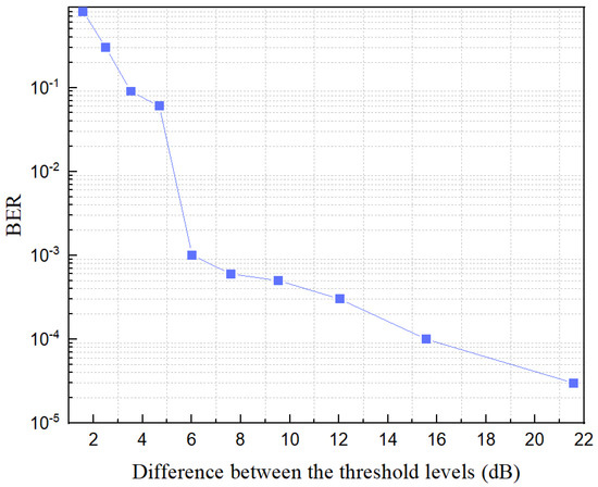
Figure 14.
BER vs. difference between two threshold levels.
5. Conclusions
In this article, a new modulation technique for vehicular OCC systems was proposed to transform the current two camera-based systems into one. The proposed system not only is economical but also overcomes several technical issues of the up-to-date standardized modulation techniques. Although OCC is a communication technique, we provided two driver-assistance systems: vehicle localization and road curvature estimation from the rear LED shapes of FWVs. Two NN-based approaches were taken to detect LEDs and estimate the road curvature. The localization resolution, data rate, and maximum communication distance could be further improved using a high-quality IS.
Author Contributions
The contribution of the authors are as follows: conceptualization, M.O.A.; methodology, M.O.A. and M.K.H.; software, M.F.A.; validation, M.O.A., M.K.H., and M.F.A.; formal analysis, M.S. and I.J.; writing—original draft preparation, M.O.A.; writing—review and editing, M.F.A., M.K.H., M.S., and M.H.R.; supervision, Y.M.J. All authors have read and agreed to the published version of the manuscript.
Funding
This work was supported in part by Institute for Information & Communications Technology Promotion (IITP) grant funded by the Korea government (MSIT) (No.2017-0-00824, Development of Intelligent and Hybrid OCC-LiFi Systems for Next Generation Optical Wireless Communications) and in part by the MSIT (Ministry of Science and ICT), Korea, under the ITRC (Information Technology Research Center) support program (IITP-2021-0-01396) supervised by the IITP (Institute for Information & Communications Technology Planning & Evaluation).
Conflicts of Interest
The authors declare no conflict of interest.
Nomenclatures
| 2D | Two-dimensional |
| 3D | Three-dimensional |
| 5G | 5th Generation |
| 6G | 6th Generation |
| BER | Bit-error-rate |
| BPPM | Bi-level pulse position modulation |
| CNN | Convolutional neural network |
| DS8-PSK | Dimmable spatial 8 phase-shift keying |
| FLV | Following vehicle |
| FWV | Forwarding vehicle |
| HS-PSK | Hybrid spatial phase-shift keying |
| ID | Identity |
| IoV | Internet of vehicles |
| IS | Image sensor |
| LED | Light-emitting-diode |
| LOS | Line-of-sight |
| MSE | Mean square error |
| NN | Neural network |
| OCC | Optical camera communication |
| RADAR | Radio detection and ranging |
| RF | Radio frequency |
| RoI | Region-of-interest |
| S2-PSK | Spatial 2 phase-shift keying |
| SNR | Signal-to-noise ratio |
| Twinkle-VPPM | Twinkle variable pulse position modulation |
| UFSOOK | Undersampled frequency-shift on–off keying |
| V2V | Vehicle to vehicle |
| V2X | Vehicle to everything |
References
- Abbott, E.; Powell, D. Land-Vehicle Navigation Using GPS. Proc. IEEE 1999, 87, 145–162. [Google Scholar] [CrossRef] [Green Version]
- Rsa, L.; Ga, M. Effects of Wireless Devices on Human Body. J. Comput. Sci. Syst. Biol. 2016, 9, 119–124. [Google Scholar] [CrossRef]
- Radiofrequency (RF) Radiation, USA. Health Physics Society. Available online: https://hps.org/hpspublications/articles/ (accessed on 3 October 2020).
- Non-Ionizing Electromagnetic Radiation in the Radiofrequency Spectrum and Its Effects on Human Health. Latin America. Available online: http://www.wirelesshealth.org.br/downloads/LatinAmericanScienceReviewReport.pdf (accessed on 3 October 2020).
- Pathak, P.H.; Feng, X.; Hu, P.; Mohapatra, P. Visible Light Communication, Networking, and Sensing: A Survey, Potential and Challenges. IEEE Commun. Surv. Tutor. 2015, 17, 2047–2077. [Google Scholar] [CrossRef]
- Nagura, T.; Yamazato, T.; Katayama, M.; Yendo, T.; Fujii, T.; Okada, H. Improved Decoding Methods of Visible Light Communication System for ITS Using LED Array and High-Speed Camera. In Proceedings of the IEEE Vehicular Technology Conference, Taipei, Taiwan, 16–19 May 2010. [Google Scholar]
- Hasan, M.K.; Le, N.T.; Shahjalal, M.; Chowdhury, M.Z.; Jang, Y.M. Simultaneous Data Transmission Using Multilevel LED in Hybrid OCC/LiFi System: Concept and Demonstration. IEEE Commun. Lett. 2019, 23, 2296–2300. [Google Scholar] [CrossRef]
- Nguyen, T.; Islam, A.; Yamazato, T.; Jang, Y.M. Technical Issues on IEEE 802.15.7m Image Sensor Communication Standardization. IEEE Commun. Mag. 2018, 56, 213–218. [Google Scholar] [CrossRef]
- Nguyen, T.; Islam, A.; Jang, Y.M. Region-of-Interest Signaling Vehicular System Using Optical Camera Communications. IEEE Photonics J. 2017, 9, 1–20. [Google Scholar] [CrossRef]
- Nguyen, T.; Islam, A.; Hossan, T.; Jang, Y.M. Current Status and Performance Analysis of Optical Camera Communication Technologies for 5G Networks. IEEE Access 2017, 5, 4574–4594. [Google Scholar] [CrossRef]
- Ahmed, M.F.; Hasan, M.K.; Shahjalal, M.; Alam, M.M.; Jang, Y.M. Experimental Demonstration of Continuous Sensor Data Monitoring Using Neural Network-Based Optical Camera Communications. IEEE Photonics J. 2020, 12, 1–11. [Google Scholar] [CrossRef]
- Ahmed, M.F.; Hasan, M.K.; Shahjalal, M.; Alam, M.M.; Jang, Y.M. Design and Implementation of an OCC-Based Real-Time Heart Rate and Pulse-Oxygen Saturation Monitoring System. IEEE Access 2020, 8, 198740–198747. [Google Scholar] [CrossRef]
- Thieu, M.D.; Pham, T.L.; Nguyen, T.; Jang, Y.M. Optical-RoI-Signaling for Vehicular Communications. IEEE Access 2019, 7, 69873–69891. [Google Scholar] [CrossRef]
- Shahjalal, M.; Hossan, M.T.; Hasan, M.K.; Chowdhury, M.Z.; Jang, Y.M. An Implementation Approach and Performance Analysis of Image Sensor Based Multilateral Indoor Localization and Navigation System. Wirel. Commun. Mob. Comput. 2018, 2018. [Google Scholar] [CrossRef] [Green Version]
- Hossan, M.T.; Chowdhury, M.Z.; Islam, A.; Jang, Y.M. A Novel Indoor Mobile Localization System Based on Optical Camera Communication. Wirel. Commun. Mob. Comput. 2018, 2018. [Google Scholar] [CrossRef] [Green Version]
- Jeng, S.; Chieng, W.; Lu, H. Estimating Speed Using a Side-Looking Single-Radar Vehicle Detector. IEEE Trans. Intell. Transp. Syst. 2014, 15, 607–614. [Google Scholar] [CrossRef]
- Kang, D.; Kum, D. Camera and Radar Sensor Fusion for Robust Vehicle Localization via Vehicle Part Localization. IEEE Access 2020, 8, 75223–75236. [Google Scholar] [CrossRef]
- Ladd, A.M.; Bekris, K.E.; Rudys, A.P.; Wallach, D.S.; Kavraki, L.E. On the Feasibility of Using Wireless Ethernet for Indoor Localization. IEEE Trans. Robot. Autom. 2004, 20, 555–559. [Google Scholar] [CrossRef] [Green Version]
- Hossan, M.T.; Chowdhury, M.Z.; Hasan, M.K.; Shahjalal, M.; Nguyen, T.; Le, N.T.; Jang, Y.M. A New Vehicle Localization Scheme Based on Combined Optical Camera Communication and Photogrammetry. Mob. Inf. Syst. 2018, 2018. [Google Scholar] [CrossRef] [Green Version]
- Ifthekhar, M.S.; Saha, N.; Jang, Y.M. Stereo-Vision-Based Cooperative-Vehicle Positioning Using OCC and Neural Networks. Opt. Commun. 2015, 352, 166–180. [Google Scholar] [CrossRef]
- Tram, V.T.B.; Yoo, M. Vehicle-to-Vehicle Distance Estimation Using a Low-Resolution Camera Based on Visible Light Communications. IEEE Access 2018, 6, 4521–4527. [Google Scholar] [CrossRef]
- Aoyama, H.; Oshima, M. Visible Light Communication Using a Conventional Image Sensor. In Proceedings of the Annual IEEE Consumer Communications and Networking Conference (CCNC), Las Vegas, NV, USA, 9–12 January 2015. [Google Scholar]
- Do, T.; Yoo, M. Multiple Exposure Coding for Short and Long Dual Transmission in Vehicle Optical Camera Communication. IEEE Access 2019, 7, 35148–35161. [Google Scholar] [CrossRef]
- Ashok, A.; Jain, S.; Gruteser, M.; Mandayam, N.; Yuan, W.; Dana, K. Capacity of Screen—Camera Communications Under Perspective Distortions. Pervasive Mob. Comput. 2015, 16, 239–250. [Google Scholar] [CrossRef]
Publisher’s Note: MDPI stays neutral with regard to jurisdictional claims in published maps and institutional affiliations. |
© 2021 by the authors. Licensee MDPI, Basel, Switzerland. This article is an open access article distributed under the terms and conditions of the Creative Commons Attribution (CC BY) license (https://creativecommons.org/licenses/by/4.0/).