
Hardware-in-the-Loop and Digital Control Techniques Applied to Single-Phase PFC Converters

 ,
,  ,
,  ,
,  and
and
Abstract
1. Introduction
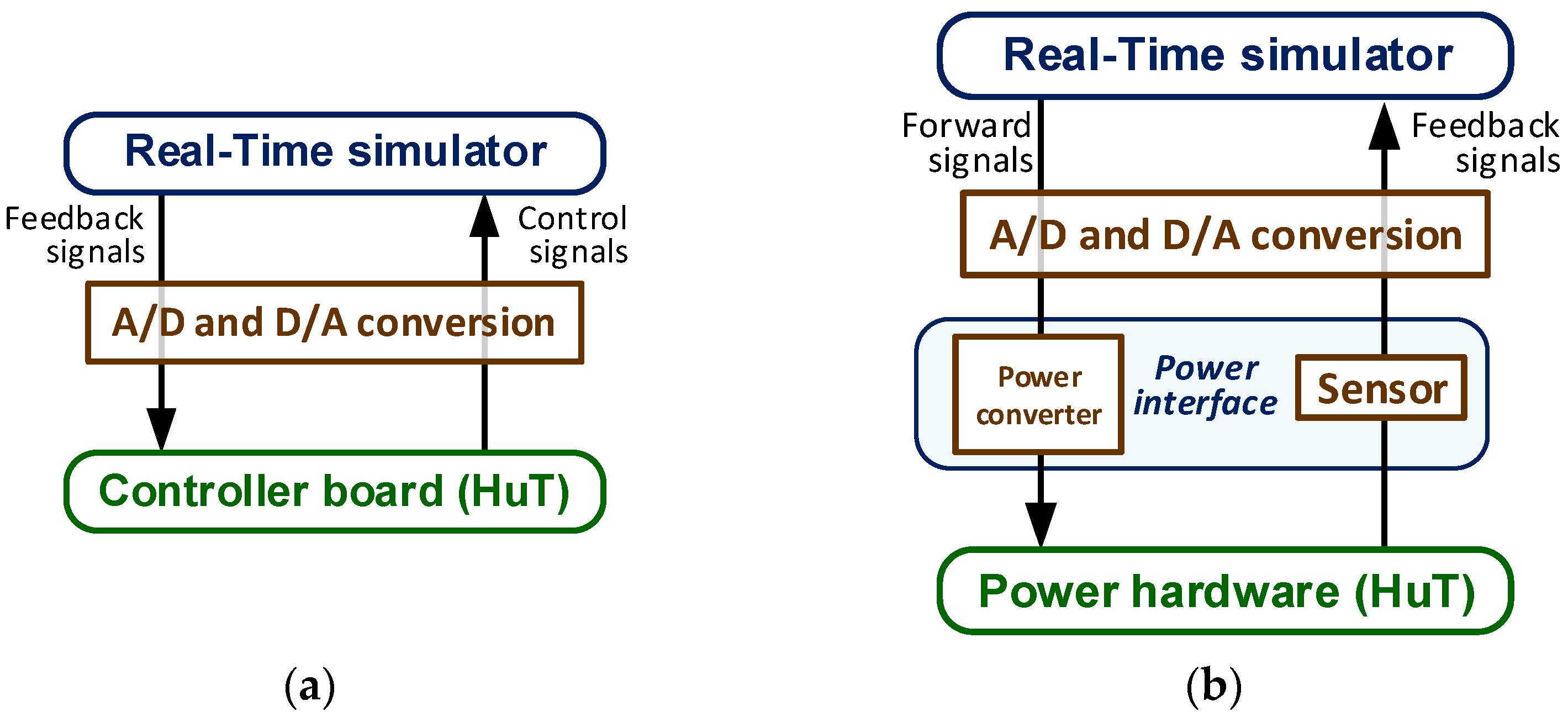
2. HIL Technology
- several processors working in parallel that jointly execute the simulation in real-time;
- a computer in which the offline model is prepared in order to subsequently upload it to the destination platform and monitor the simulation results in real-time;
- input and output terminals to interact with external hardware and
- a communication system that allows the exchange of data between the different blocks that make up the system.
Commercial HIL
3. Converter Modeling
3.1. Mathematical Model
3.2. Arithmetical Possibilities
- Real Arithmetic: this is the standard numeric type that uses double-precision floating-point format. It cannot be synthesized, but it is useful to create a first approximation.
- Float Arithmetic: this is a synthesizable floating-point arithmetic. It has the versatility of floating point, but it needs many hardware resources.
- Fixed Arithmetic: this is a fixed-point arithmetic. The designer must decide the number of bits to the integer and the fractional parts of every variable, and it needs much more design effort.
4. Test
- -
- Statistical tests [61], such as the Monte Carlo method, that require multiple iterations to simulate failure cases.
- -
- Low-cost multi-solver real-time simulation environment [62], namely the real-time extension of the virtual test bed (VTB-RT). In this proposal, for a given hardware platform, the minimum time resolution is limited and only a limited bandwidth of the system under test can be used. So it is necessary to pay attention to the compromise between the VTB-RT platform cost and the bandwidth of the system under test.
- -
- Reconfigurable HIL based on a top-down design flow [63] analyzed through a fault-tolerant shunt active power filter application. In [64], it is also shown how HIL devices are used to assist in the design, optimization and quality assurance of controllers from the early design stage all the way to the type testing and release testing stage.
- -
- HIL for the validation, in the time and frequency domains, of the input and output impedances of converters achieving ultra-low latency in real time [65]. This work also shows a comparison between real-time emulation and a reference hardware design under steady-state and transient conditions.
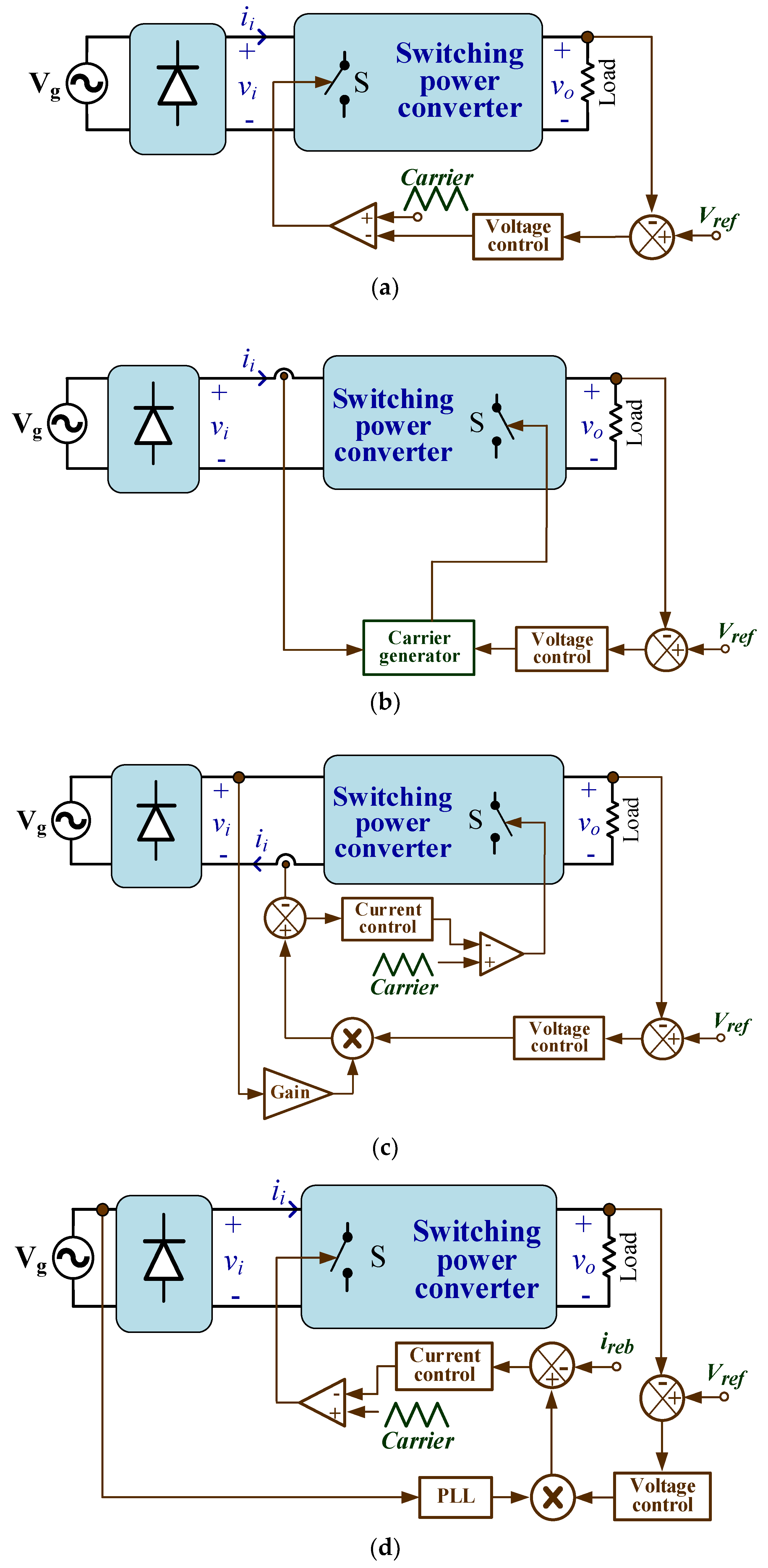
5. Digital Control
- Group I: Operation in discontinuous conduction mode (DCM) or the boundary condition between the continuous conduction mode (CCM) and DCM (Figure 2a).
- Group II: Non-linear carrier (NLC) control of the line current, where the switching instants are identified by the comparison of the current with a carrier signal, hysteresis band or a sliding surface that imposes the proportionality between the peak, valley, or average current and the input voltage in each switching period (Figure 2b).
- Group III: Linear control of the average current. Noise immunity improves compared to the NLC technique at the expense of reducing the bandwidth of the current control (Figure 2c).
- Group IV: Phasor-based control. The input voltage is assumed to be sinusoidal, so the modulation function that imposes the line current must be sinusoidal (Figure 2d).
- Its bandwidth of the current acquisition stage is smaller than in the non-linear version.
- In bidirectional PFCs, the non-linear control may exhibit non-stable operating conditions.
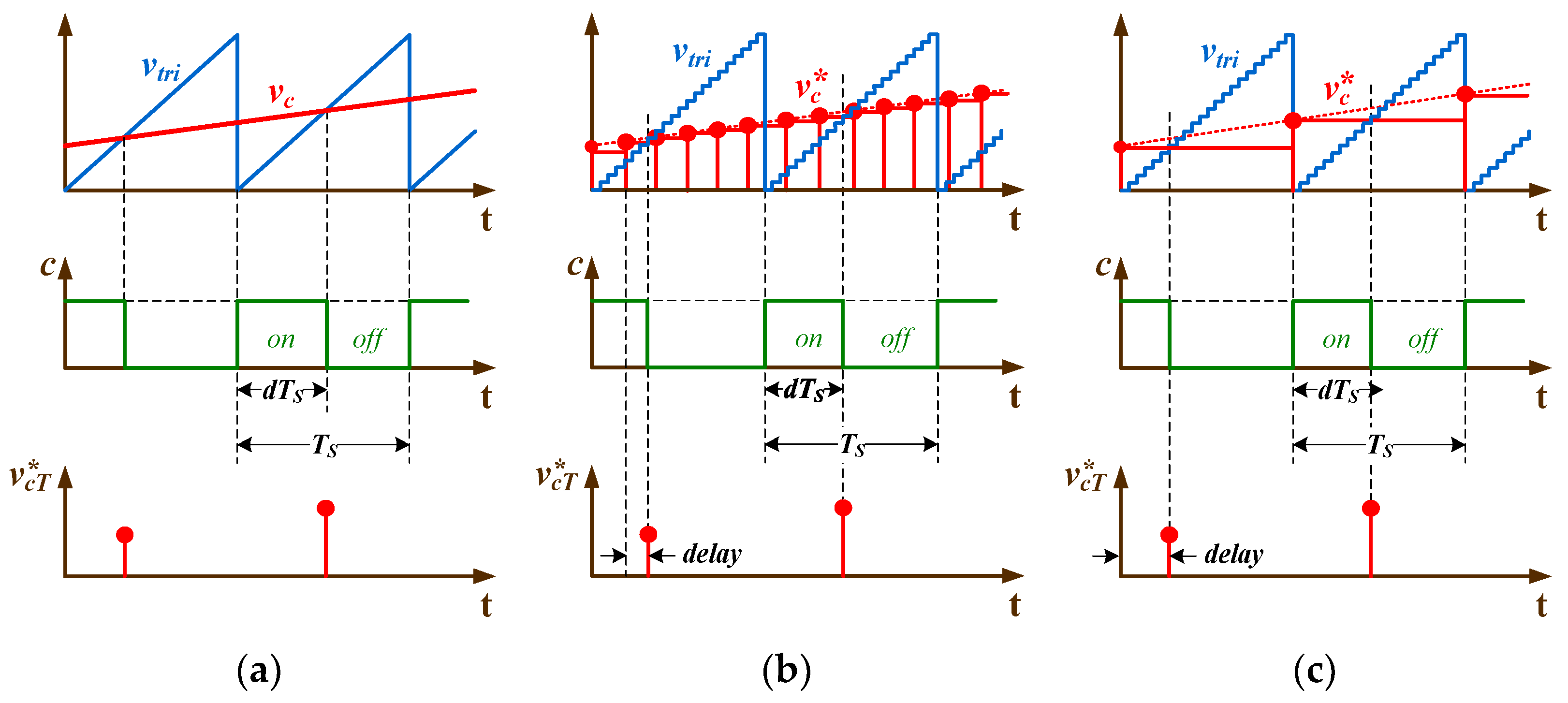
PWM
6. Conclusions
Author Contributions
Funding
Conflicts of Interest
References
- Commission, I.E. Electromagnetic Compatibility EMC—Part 3-2: Limits for Harmonic Current Emissions (Equipment Input Current ≤ 16 A per Phase); 2021; Volume 2. Available online: https://infostore.saiglobal.com/preview/422560892461.pdf?sku=1144674_SAIG_NSAI_NSAI_2712803 (accessed on 24 June 2021).
- Nguyen, H.V.; Lee, D. Reducing the Dc-Link Capacitance: A Bridgeless PFC Boost Rectifier That Reduces the Second-Order Power Ripple at the Dc Output. IEEE Ind. Appl. Mag. 2018, 24, 23–34. [Google Scholar] [CrossRef]
- Potera, R.R.; Han, T.J. Silicon Carbide Diodes in Power-Factor Correction Circuits: Device and Circuit Design Aspects. IEEE Power Electron. Mag. 2019, 6, 34–39. [Google Scholar] [CrossRef]
- Yan, S.; Tan, S.; Lee, C.; Chaudhuri, B.; Hui, S.Y.R. Use of Smart Loads for Power Quality Improvement. IEEE J. Emerging Sel. Top. Power Electron. 2017, 5, 504–512. [Google Scholar] [CrossRef]
- Ghosh, S.; Giambiasi, N. Modeling and Simulation of Mixed-Signal Electronic Designs—Enabling Analog and Discrete Subsystems to Be Represented Uniformly within a Single Framework. IEEE Circuits Devices Mag. 2006, 22, 47–52. [Google Scholar] [CrossRef]
- Pecheux, F.; Lallement, C.; Vachoux, A. VHDL-AMS and Verilog-AMS as Alternative Hardware Description Languages for Efficient Modeling of Multidiscipline Systems. IEEE Trans. Comput. Aided Des. Integr. Circuits Syst. 2005, 24, 204–225. [Google Scholar] [CrossRef]
- Sanchez, A.; de Castro, A.; Garrido, J. A Comparison of Simulation and Hardware-in-the- Loop Alternatives for Digital Control of Power Converters. IEEE Trans. Ind. Inform. 2012, 8, 491–500. [Google Scholar] [CrossRef]
- Larruscain, G.; Tapia, G.; Susperregui, A.; Martinez, M.I. Student-Tailored Final Year Project on Microcontroller-Based Hardware-in-the-Loop Speed Control of a Wind Generator. Int. J. Electr. Eng. Educ. 2018, 55, 213–233. [Google Scholar] [CrossRef]
- Ahmad, Z.; Torres, J.R.; Veera Kumar, N.; Rakhshani, E.; Palensky, P.; van der Meijden, M. A Power Hardware-in-the-Loop Based Method for FAPR Compliance Testing of the Wind Turbine Converters Control. Energies 2020, 13, 5203. [Google Scholar] [CrossRef]
- Ledin, J.A. Hardware-in-the-Loop Simulation. 1999. Available online: https://idsc.ethz.ch/content/dam/ethz/special-interest/mavt/dynamic-systems-n-control/idsc-dam/Lectures/Embedded-Control-Systems/AdditionalMaterial/Applications/APP_Hardware-in-the-Loop_Simulation.pdf (accessed on 24 June 2021).
- Ren, W.; Steurer, M.; Baldwin, T.L. Improve the Stability and the Accuracy of Power Hardware-in-the-Loop Simulation by Selecting Appropriate Interface Algorithms. IEEE Trans. Ind. Appl. 2008, 44, 1286–1294. [Google Scholar] [CrossRef]
- Jia, J.; Yang, G.; Nielsen, A.H.; Roenne-Hansen, P. Hardware-in-the-Loop Tests on Distance Protection Considering VSC Fault-Ride-through Control Strategies. J. Eng. 2018, 2018, 824–829. [Google Scholar] [CrossRef]
- Vu, P.; Nguyen, Q.; Tran, M.; Todeschini, G.; Santoso, S. Adaptive Backstepping Approach for Dc-Side Controllers of Z-Source Inverters in Grid-Tied PV System Applications. IET Power Electron. 2018, 11, 2346–2354. [Google Scholar] [CrossRef]
- Amin, M.; Aziz, G.A.A.; Durkin, J.; Mohammed, O.A. A Hardware-in-the-Loop Realization of Speed Sensorless Control of PMa-SynRM With Steady-State and Transient Performances Enhancement. IEEE Trans. Ind. Appl. 2019, 55, 5331–5342. [Google Scholar] [CrossRef]
- Tian, J.; Liu, J.; Shu, J.; Tang, J.; Yang, J. Engineering Modelling of Wind Turbine Applied in Real-Time Simulation with Hardware-in-Loop and Optimising Control. IET Power Electron. 2018, 11, 2490–2498. [Google Scholar] [CrossRef]
- Kotsampopoulos, P.C.; Kleftakis, V.A.; Hatziargyriou, N.D. Laboratory Education of Modern Power Systems Using PHIL Simulation. IEEE Trans. Power Syst. 2017, 32, 3992–4001. [Google Scholar] [CrossRef]
- García-Martínez, E.; Sanz, J.F.; Muñoz-Cruzado, J.; Perié, J.M. A Review of PHIL Testing for Smart Grids—Selection Guide, Classification and Online Database Analysis. Electronics 2020, 9, 382. [Google Scholar] [CrossRef]
- El Mariachet, J.; Guan, Y.; Matas, J.; Martín, H.; Li, M.; Guerrero, J.M. HIL-Assessed Fast and Accurate Single-Phase Power Calculation Algorithm for Voltage Source Inverters Supplying to High Total Demand Distortion Nonlinear Loads. Electronics 2020, 9, 1643. [Google Scholar] [CrossRef]
- Lucía, Ó.; Urriza, I.; Barragán, L.A.; Navarro, D.; Jiménez, Ó.; Burdío, J.M. Real-Time FPGA-Based Hardware-in-the-Loop Simulation Test Bench Applied to Multiple-Output Power Converters. IEEE Trans. Ind. Appl. 2011, 47, 853–860. [Google Scholar] [CrossRef]
- Sankaranarayanan, V.; Shirazi, M.; Gao, Y.; Ghosh, A.; Erickson, R.W.; Maksimovic, D. Controller Hardware-in-the-Loop Validation of a Modular Control Architecture for a Composite DC-DC Converter. In Proceedings of the 2019 20th Workshop on Control and Modeling for Power Electronics (COMPEL), Toronto, ON, Canada, 16–19 June 2019; pp. 1–7. [Google Scholar]
- Saralegui, R.; Sanchez, A.; Martínez-García, M.S.; Novo, J.; Castro, A. de Comparison of Numerical Methods for Hardware-In-the-Loop Simulation of Switched-Mode Power Supplies. In Proceedings of the 2018 IEEE 19th Workshop on Control and Modeling for Power Electronics (COMPEL), Padova, Italy, 25–28 June 2018; pp. 1–6. [Google Scholar]
- Karaarslan, A. The Application of Hardware in the Loop for Single Phase Converters Based on DSP Controller at Solar Energy Systems. Int. J. Electr. Energy 2016, 4, 127–132. [Google Scholar] [CrossRef][Green Version]
- Kiffe, A.; Schulte, T. FPGA-Based Hardware-in-the-Loop Simulation of a Rectifier with Power Factor Correction. In Proceedings of the 2015 17th European Conference on Power Electronics and Applications (EPE’15 ECCE-Europe), Geneva, Switzerland, 8–10 September 2015; pp. 1–8. [Google Scholar]
- Woods, R.; McAllister, J.; Lightbody, G.; Yi, Y. FPGA-Based Implementation of Signal Processing Systems, 2nd ed.; John Wiley & Sons Inc.: Hoboken, NJ, USA, 2017; ISBN 978-1-119-07795-4. [Google Scholar]
- Faruque, M.D.O.; Strasser, T.; Lauss, G.; Jalili-Marandi, V.; Forsyth, P.; Dufour, C.; Dinavahi, V.; Monti, A.; Kotsampopoulos, P.; Martinez, J.A.; et al. Real-Time Simulation Technologies for Power Systems Design, Testing, and Analysis. IEEE Power Energy Technol. Syst. J. 2015, 2, 63–73. [Google Scholar] [CrossRef]
- Jandaghi, B.; Dinavahi, V. Hardware-in-the-Loop Emulation of Linear Induction Motor Drive for MagLev Application. IEEE Trans. Plasma Sci. 2016, 44, 679–686. [Google Scholar] [CrossRef]
- Parma, G.G.; Dinavahi, V. Real-Time Digital Hardware Simulation of Power Electronics and Drives. IEEE Trans. Power Deliv. 2007, 22, 1235–1246. [Google Scholar] [CrossRef]
- Matar, M.; Iravani, R. FPGA Implementation of the Power Electronic Converter Model for Real-Time Simulation of Electromagnetic Transients. IEEE Trans. Power Deliv. 2010, 25, 852–860. [Google Scholar] [CrossRef]
- Montano, F.; Ould-Bachir, T.; David, J.P. An Evaluation of a High-Level Synthesis Approach to the FPGA-Based Submicrosecond Real-Time Simulation of Power Converters. IEEE Trans. Ind. Electron. 2018, 65, 636–644. [Google Scholar] [CrossRef]
- Martínez-García, M.S.; de Castro, A.; Sanchez, A.; Garrido, J. Word Length Selection Method for HIL Power Converter Models. Int. J. Electr. Power Energy Syst. 2021, 129, 106721. [Google Scholar] [CrossRef]
- Monti, A.; Stevic, M.; Vogel, S.; Doncker, R.W.D.; Bompard, E.; Estebsari, A.; Profumo, F.; Hovsapian, R.; Mohanpurkar, M.; Flicker, J.D.; et al. A Global Real-Time Superlab: Enabling High Penetration of Power Electronics in the Electric Grid. IEEE Power Electron. Mag. 2018, 5, 35–44. [Google Scholar] [CrossRef]
- Nigam, S.; Ajala, O.; Dominguez-Garcia, A.D. A Controller Hardware-in-the-Loop Testbed: Verification and Validation of Microgrid Control Architectures. IEEE Electrif. Mag. 2020, 8, 92–100. [Google Scholar] [CrossRef]
- Vijay, A.S.; Doolla, S.; Chandorkar, M.C. Real-Time Testing Approaches for Microgrids. IEEE J. Emerg. Sel. Top. Power Electron. 2017, 5, 1356–1376. [Google Scholar] [CrossRef]
- Sanchez, A.; de Castro, A.; Garrido, J. Parametrizable Fixed-Point Arithmetic for HIL With Small Simulation Steps. IEEE J. Emerg. Sel. Top. Power Electron. 2019, 7, 2467–2475. [Google Scholar] [CrossRef]
- Ibarra, L.; Rosales, A.; Ponce, P.; Molina, A.; Ayyanar, R. Overview of Real-Time Simulation as a Supporting Effort to Smart-Grid Attainment. Energies 2017, 10, 817. [Google Scholar] [CrossRef]
- Rodríguez-Andina, J.J.; Valdés-Peña, M.D.; Moure, M.J. Advanced Features and Industrial Applications of FPGAs—A Review. IEEE Trans. Ind. Inform. 2015, 11, 853–864. [Google Scholar] [CrossRef]
- SpHIL. Sp Control Technologies. Available online: http://spcontroltechnologies.com/sphil/ (accessed on 24 June 2021).
- Chakraborty, S.; Mazuela, M.; Tran, D.-D.; Corea-Araujo, J.A.; Lan, Y.; Loiti, A.A.; Garmier, P.; Aizpuru, I.; Hegazy, O. Scalable Modeling Approach and Robust Hardware-in-the-Loop Testing of an Optimized Interleaved Bidirectional HV DC/DC Converter for Electric Vehicle Drivetrains. IEEE Access 2020, 8, 115515–115536. [Google Scholar] [CrossRef]
- Guillaud, X.; Faruque, M.O.; Teninge, A.; Hariri, A.H.; Vanfretti, L.; Paolone, M.; Dinavahi, V.; Mitra, P.; Lauss, G.; Dufour, C.; et al. Applications of Real-Time Simulation Technologies in Power and Energy Systems. IEEE Power Energy Technol. Syst. J. 2015, 2, 103–115. [Google Scholar] [CrossRef]
- Parizad, A.; Mohamadian, S.; Iranian, M.E.; Guerrero, J.M. Power System Real-Time Emulation: A Practical Virtual Instrumentation to Complete Electric Power System Modeling. IEEE Trans. Ind. Inform. 2019, 15, 889–900. [Google Scholar] [CrossRef]
- Jafarian, H.; Kim, N.; Parkhideh, B. Decentralized Control Strategy for AC-Stacked PV Inverter Architecture Under Grid Background Harmonics. IEEE J. Emerg. Sel. Top. Power Electron. 2018, 6, 84–93. [Google Scholar] [CrossRef]
- Srdic, S.; Liang, X.; Zhang, C.; Yu, W.; Lukic, S. A SiC-Based High-Performance Medium-Voltage Fast Charger for Plug-in Electric Vehicles. In Proceedings of the 2016 IEEE Energy Conversion Congress and Exposition (ECCE), Milwaukee, WI, USA, 18–22 September 2016; pp. 1–6. [Google Scholar]
- CRTS (HIL). Available online: https://powersmartcontrol.com/solutions/crts-hil/ (accessed on 2 May 2021).
- Delavari, A.; Brunelle, P.; Kamwa, I. Real-Time Closed-Loop PQ Control of NPC Multi-Level Converter Using OPAL-RT and Speedgoat Simulators. In Proceedings of the 2018 IEEE Electrical Power and Energy Conference (EPEC), Toronto, ON, Canada, 10–11 October 2018; pp. 1–5. [Google Scholar]
- Martínez, J.R.; Rengifo, H.R.; Córdoba, J.S.; Palacios, J.; Posada, J. Design and Implementation of a Multiplier SEPIC Converter to Emulate a Photovoltaic System Using Power HIL. In Proceedings of the 2019 FISE-IEEE/CIGRE Conference—Living the energy Transition (FISE/CIGRE), Medellin, Colombia, 4–6 December 2019; pp. 1–7. [Google Scholar]
- Estrada, L.; Vázquez, N.; Vaquero, J.; de Castro, Á.; Arau, J. Real-Time Hardware in the Loop Simulation Methodology for Power Converters Using LabVIEW FPGA. Energies 2020, 13, 373. [Google Scholar] [CrossRef]
- Zamiri, E.; Sanchez, A.; Yushkova, M.; Martínez-García, M.S.; de Castro, A. Comparison of Different Design Alternatives for Hardware-in-the-Loop of Power Converters. Electronics 2021, 10, 926. [Google Scholar] [CrossRef]
- Carpiuc, S.; Schiesser, M.; Villegas, C. Current Control and FPGA–Based Real–Time Simulation of Grid–Tied Inverters. In Proceedings of the 2020 22nd European Conference on Power Electronics and Applications (EPE’20 ECCE Europe), Lyon, France, 7–10 September 2020; pp. P.1–P.7. [Google Scholar]
- Amor Peinado, P. Estudio Avanzado de Herramientas Comerciales En HIL; Universidad Autónoma de Madrid: Madrid, Spain, 2020. [Google Scholar]
- Ayachit, A.; Kazimierczuk, M.K. Averaged Small-Signal Model of PWM DC-DC Converters in CCM Including Switching Power Loss. IEEE Trans. Circuits Syst. II Express Briefs 2019, 66, 262–266. [Google Scholar] [CrossRef]
- Narimani, M.; Moschopoulos, G. Modeling and Control of a Single-Stage Three-Level Power Factor Correction AC-DC Converter. In Proceedings of the 2011 24th Canadian Conference on Electrical and Computer Engineering(CCECE), Niagara Falls, ON, Canada, 8–11 May 2011; pp. 000583–000586. [Google Scholar]
- Bai, H.; Liu, C.; Breaz, E.; Al-Haddad, K.; Gao, F. A Review on the Device-Level Real-Time Simulation of Power Electronic Converters: Motivations for Improving Performance. IEEE Ind. Electron. Mag. 2021, 15, 12–27. [Google Scholar] [CrossRef]
- Eickson, R.W.; Maksimovic, D. Fundamentals of Power Electronics, 2nd ed.; Springer: Norwell, MA, USA, 2001; ISBN 978-0-7923-7270-7. [Google Scholar]
- Ji, F.; Fan, H.; Sun, Y. Modelling a FPGA-Based LLC Converter for Real-Time Hardware-in-the-Loop (HIL) Simulation. In Proceedings of the 2016 IEEE 8th International Power Electronics and Motion Control Conference (IPEMC-ECCE Asia), Hefei, China, 22–26 May 2016; pp. 1016–1019. [Google Scholar]
- Sira-Ramirez, H.; deNieto, M.D. A Lagrangian Approach to Average Modeling of Pulsewidth-Modulation Controlled DC-to-DC Power Converters. IEEE Trans. Circuits Syst. I Fundam. Theory Appl. 1996, 43, 427. [Google Scholar] [CrossRef]
- Rosa, A.H.R.; Morais, L.M.F.; Seleme, I.S. Hardware in the Loop Simulation of Non Linear Control Methods Applied for Power Converters. In Proceedings of the 2015 IEEE 13th Brazilian Power Electronics Conference and 1st Southern Power Electronics Conference (COBEP/SPEC), Fortaleza, Brazil, 29 November–2 December 2015; pp. 1–6. [Google Scholar]
- NAVARRO, D.; CORTES, D.; GALAZ-LARIOS, M. A Port-Hamiltonian Approach to Control DC-DC Power Converters. Stud. Inform. Control. 2017, 26. [Google Scholar] [CrossRef]
- Rosa, A.H.R.; Morais, L.M.F.; Seleme, I.S. A Study and Comparison of Nonlinear Control Techniques Apply to Second Order Power Converters Using HIL Simulation. In Proceedings of the 2016 12th IEEE International Conference on Industry Applications (INDUSCON), Curitiba, Brazil, 20–23 November 2016; pp. 1–8. [Google Scholar]
- Dufour, C.; Cense, S.; Bélanger, J. FPGA-Based Switched Reluctance Motor Drive and DC-DC Converter Models for High-Bandwidth HIL Real-Time Simulator. In Proceedings of the 2013 15th European Conference on Power Electronics and Applications (EPE), Lille, France, 2–6 September 2013; pp. 1–8. [Google Scholar]
- Lamo, P.; de Castro, Á.; Brañas, C.; Azcondo, F.J. Emulator of a Boost Converter for Educational Purposes. Electronics 2020, 9, 1883. [Google Scholar] [CrossRef]
- Paquin, J.; Belanger, J.; Snider, L.A.; Pirolli, C. Wei Li Monte-Carlo Study on a Large-Scale Power System Model in Real-Time Using EMEGAsim. In Proceedings of the 2009 IEEE Energy Conversion Congress and Exposition, San Jose, CA, USA, 20–24 September 2009; pp. 3194–3202. [Google Scholar]
- Lu, B.; Wu, X.; Figueroa, H.; Monti, A. A Low-Cost Real-Time Hardware-in-the-Loop Testing Approach of Power Electronics Controls. IEEE Trans. Ind. Electron. 2007, 54, 919–931. [Google Scholar] [CrossRef]
- Karimi, S.; Poure, P.; Saadate, S. An HIL-Based Reconfigurable Platform for Design, Implementation, and Verification of Electrical System Digital Controllers. IEEE Trans. Ind. Electron. 2010, 57, 1226–1236. [Google Scholar] [CrossRef]
- Adzic, E.; Grabic, S.; Vekic, M.; Porobic, V.; Celanovic, N.F. Hardware-in-the-Loop Optimization of the 3-Phase Grid Connected Converter Controller. In Proceedings of the IECON 2013—39th Annual Conference of the IEEE Industrial Electronics Society, Vienna, Austria, 10–13 November 2013; pp. 5392–5397. [Google Scholar]
- Chai, E.; Celanovic, I.; Poon, J. Validation of Frequency- and Time-Domain Fidelity of an Ultra-Low Latency Hardware-in-the-Loop (HIL) Emulator. In Proceedings of the 2013 IEEE 14th Workshop on Control and Modeling for Power Electronics (COMPEL), Salt Lake City, UT, USA, 23–26 June 2013; pp. 1–5. [Google Scholar]
- Grégoire, L.; Al-Haddad, K.; Nanjundaiah, G. Hardware-in-the-Loop (HIL) to Reduce the Development Cost of Power Electronic Converters. In Proceedings of the India International Conference on Power Electronics 2010 (IICPE2010), New Delhi, India, 28–30 January 2011; pp. 1–6. [Google Scholar]
- Lamo, P.; Ruiz, G.A.; Pigazo, A.; Azcondo, F.J. Low THDi Controller for Current Sensorless Single Phase Rectifiers Using a Two-Sample Phase Locked Loop. In Proceedings of the 2019 20th Workshop on Control and Modeling for Power Electronics (COMPEL), Toronto, CO, Canada, 17–20 June 2019; pp. 1–5. [Google Scholar]
- Lopez, V.M.; Azcondo, F.J.; de Castro, A.; Zane, R. Universal Digital Controller for Boost CCM Power Factor Correction Stages Based on Current Rebuilding Concept. Power Electron. IEEE Trans. 2014, 29, 3818–3829. [Google Scholar] [CrossRef]
- Sanchez, A.; de Castro, A.; López, V.M.; Azcondo, F.J.; Garrido, J. Single ADC Digital PFC Controller Using Precalculated Duty Cycles. IEEE Trans. Power Electron. 2014, 29, 996–1005. [Google Scholar] [CrossRef]
- López, F.; López-Martín, V.M.; Azcondo, F.J.; Corradini, L.; Pigazo, A. Current-Sensorless Power Factor Correction With Predictive Controllers. IEEE J. Emerg. Sel. Top. Power Electron. 2019, 7, 891–900. [Google Scholar] [CrossRef]
- Rosa, A.H.R.; De Souza, T.M.; Morais, L.M.F.; Seleme, S.I. Adaptive and Nonlinear Control Techniques Applied to SEPIC Converter in DC-DC, PFC, CCM and DCM Modes Using HIL Simulation. Energies 2018, 11, 602. [Google Scholar] [CrossRef]
- Rosa, A.H.R.; Morais, L.M.F.; Fortes, G.O.; Seleme Júnior, S.I. Practical Considerations of Nonlinear Control Techniques Applied to Static Power Converters: A Survey and Comparative Study. Int. J. Electr. Power Energy Syst. 2021, 127, 106545. [Google Scholar] [CrossRef]
- Bouafassa, A.; Fernández-Ramírez, L.M.; Babes, B. Power Quality Improvements of Arc Welding Power Supplies by Modified Bridgeless SEPIC PFC Converter. J. Power Electron. 2020, 20, 1445–1455. [Google Scholar] [CrossRef]
- Amiri, P.; Gautam, D.; Botting, C.; Eberle, W.; Wang, L. Real-Time Hardware-in-the-Loop Simulation and Control of Totem Pole PFC Converter. In Proceedings of the 2020 IEEE 21st Workshop on Control and Modeling for Power Electronics (COMPEL), Aalborg, Denmark, 9–12 November 2020; pp. 1–7. [Google Scholar]
- Monmasson, E.; Cirstea, M.N. FPGA Design Methodology for Industrial Control Systems—A Review. IEEE Trans. Ind. Electron. 2007, 54, 1824–1842. [Google Scholar] [CrossRef]
- Corradini, L. Analysis and Implementation of Digital Control Architectures for DC-DC Switching Converters. Ph.D. Thesis, University of Padua, Padova, Italy, January 2008. [Google Scholar]
- Peterchev, A.V.; Sanders, S.R. Quantization Resolution and Limit Cycling in Digitally Controlled PWM Converters. IEEE Trans. Power Electron. 2003, 18, 301–308. [Google Scholar] [CrossRef]
- Kang, R.; Kim, S.; Yang, I.; Jeong, K.; Kang, C.; Kim, G. The Use of FPGA in HIL Simulation of Three Phase Interleaved DC-DC Converter. In Proceedings of the 2012 IEEE Vehicle Power and Propulsion Conference, Seoul, Korea, 9–12 October 2012; pp. 772–776. [Google Scholar]
- Van de Sype, D.M.; De Gusseme, K.; Van den Bossche, A.P.; Melkebeek, J.A. Small-Signal Laplace-Domain Analysis of Uniformly-Sampled Pulse-Width Modulators. In Proceedings of the 2004 IEEE 35th Annual Power Electronics Specialists Conference (IEEE Cat. No.04CH37551), Aachen, Germany, 20–25 June 2004; Volume 6, pp. 4292–4298. [Google Scholar]
- HIL602|Typhoon HIL.HIL. Available online: https://www.typhoon-hil.com/ (accessed on 24 June 2021).


| Typhoon HIL | LabVIEW | Simulink | |||
|---|---|---|---|---|---|
| Control Design & Simulation | LabVIEW FPGA | Real Time Desktop | Real Time | ||
| Solvers | Exact Trapezoidal Euler | Runge-Kutta 1 (Euler), 2, 3, 4, 23 (variable), 45 (variable) BDF (variable) Adams-Moulton (variable) Rosenbrock (variable) Discrete States Only SDIRK4 (variable) Radau 5, 9, 13 (Variable Order) (variable) Gear’s Method (variable) | The solver used is defined in the logical and mathematical model chosen during the realization of each design. | Discrete (no continuous states) Ode8 (Dormand-Prince) Ode5 (Dormand-Prince) Ode4 (Runge-Kutta) Ode3 (Bogacki-Shampirne) Ode2 (Heun) Ode1 (Euler) Ode14x (extrapolation) | |
| Data acquisition | Allows data export in various formats during simulation in HIL SCADA (CSV, HDF5, HDF5, MAT, TDMS) HIL402 has built-in oscilloscopes. | Allows to export results directly in Excel or clipboard. | Need other hardware to display the simulated signals. | The data of the different signals can be saved and/or plotted. | |
| Clock frequency | With the HIL402 hardware virtual machine: 50 MHz | Simulating loops of “Control Design & Simulation” at different frequencies (1 kHz, 1 MHz and in between). Maximum frequency in real time (RT): 1 kHz | MyRIO-1900 Maximum Clock Rate with Zynq-7000 FPGA: 40 MHz | Maximum possible frequency in real time (RT) in normal mode: 1 kHz In external mode: 20 kHz | Depends on the hardware to be used. |
| Switching frequency | With the HIL402 hardware virtual machine: 200 kHz | The switching frequency shall not be higher than the clock: 1 kHz | Depends on the hardware to be used, but never higher than the clock frequency: 40 MHz | In normal mode: 1 kHz In external mode it is a function of the selected Duty: fSW = fCLK × Duty | Depends on the hardware to be used. |
| Minimum simulation step | With HIL402 hardware: 500 ns | 1 ms | Depends on the model with a theoretical minimum of 25 ns (40 MHz clock). | In normal mode: 1 ms In external mode: 50 μs | |
| Real Time simulation | Works in Real Time on the HIL402 virtual machine. | Simulation at various frequencies (on a PC with 1 kHz clocks or derivatives and with a 1 MHz NI HW or similar), but to be a real real-time simulation, only 1 kHz is allowed with steps or steps of periods of 1 ms. | Realtime on specified NI hardware: myRIO-1900. | In real time at the specified frequencies using the computer’s own processor. In external mode the circuit model is converted to a C/C ++ model which implies a higher frequency to simulate. | In real time on the hardware connected to the equipment and linked to the designed model. |
| Resource utilization/occupied area | Shows summary of HW resources, memory and SW size. Use more high-level built-in resources. | Does not show details. | During the board design, the report shows low-level components (slices, LUTs, DSPs…). | Allows analysis of the use of resources. | |
| Licensing | Free “Typhoon HIL Control Center” software download and registration. Virtual machine with a 1-year license. | LabView 2019 and Multisim 14.2 require a license or the 45-day free trial. | Need the NI myRIO module included with the hardware, and the LabVIEW FPGA payment module. | Simulink Real Time Desktop (not Simulink Real Time) requires license. To make the circuit designs, you need a paid “Simscape Electrical” or a 1-month free trial version. | |
| Type of simulation | On-line | Off-line | On-line | Off-line | On-line |
| Proposal | Mathematical Model | Converter | Experimental Verification | Platform |
|---|---|---|---|---|
| [47] | LTI + State Space | LLC resonant | PSIM | FPGA |
| [24] | Average switch approach | AC-DC PFC | MATLAB/Simulink (CHIL simulation) | PC |
| [34] | State space/Euler Lagrange | Buck | LT3430-1/LTC3892-1/MAX1685 | FPGA |
| [50] | Euler-Lagrange | Boost, Buck and SEPIC | MATLAB/Simulink (Real plant) | DSP |
| [25] | Padé approximation with oversampling | Rectifier PFC | MATLAB/Simulation (Real plant) | FPGA |
| Operation | DSP48E | LUT | Timing |
|---|---|---|---|
| float32 × float32 | 3 | 135 | 52.435 ns |
| float32 + float32 | 2 | 195 | 88.970 ns |
| int32 × int32 | 4 | 231 | 19.315 ns |
| int32 + int32 | 0 | 186 | 4.658 ns |
| Operation | DSP48E | LUT | Timing |
|---|---|---|---|
| float32 × float32 | 0 | 675 | 78.780 ns |
| float32 × float32 | 1 | 267 | 67.505 ns |
| float32 × float32 | 2 | 122 | 54.690 ns |
| float32 × float32 | 3 | 135 | 52.435 ns |
Publisher’s Note: MDPI stays neutral with regard to jurisdictional claims in published maps and institutional affiliations. |
© 2021 by the authors. Licensee MDPI, Basel, Switzerland. This article is an open access article distributed under the terms and conditions of the Creative Commons Attribution (CC BY) license (https://creativecommons.org/licenses/by/4.0/).
Share and Cite
Lamo, P.; de Castro, A.; Sanchez, A.; Ruiz, G.A.; Azcondo, F.J.; Pigazo, A. Hardware-in-the-Loop and Digital Control Techniques Applied to Single-Phase PFC Converters. Electronics 2021, 10, 1563. https://doi.org/10.3390/electronics10131563
Lamo P, de Castro A, Sanchez A, Ruiz GA, Azcondo FJ, Pigazo A. Hardware-in-the-Loop and Digital Control Techniques Applied to Single-Phase PFC Converters. Electronics. 2021; 10(13):1563. https://doi.org/10.3390/electronics10131563
Chicago/Turabian StyleLamo, Paula, Angel de Castro, Alberto Sanchez, Gustavo A. Ruiz, Francisco J. Azcondo, and Alberto Pigazo. 2021. "Hardware-in-the-Loop and Digital Control Techniques Applied to Single-Phase PFC Converters" Electronics 10, no. 13: 1563. https://doi.org/10.3390/electronics10131563
APA StyleLamo, P., de Castro, A., Sanchez, A., Ruiz, G. A., Azcondo, F. J., & Pigazo, A. (2021). Hardware-in-the-Loop and Digital Control Techniques Applied to Single-Phase PFC Converters. Electronics, 10(13), 1563. https://doi.org/10.3390/electronics10131563