
Cost-Efficient EM-Driven Size Reduction of Antenna Structures by Multi-Fidelity Simulation Models


Abstract
:1. Introduction
2. Optimization-Based Antenna Miniaturization with Multi-Fidelity Simulations
2.1. Optimization-Based Size Reduction. Problem Formulation
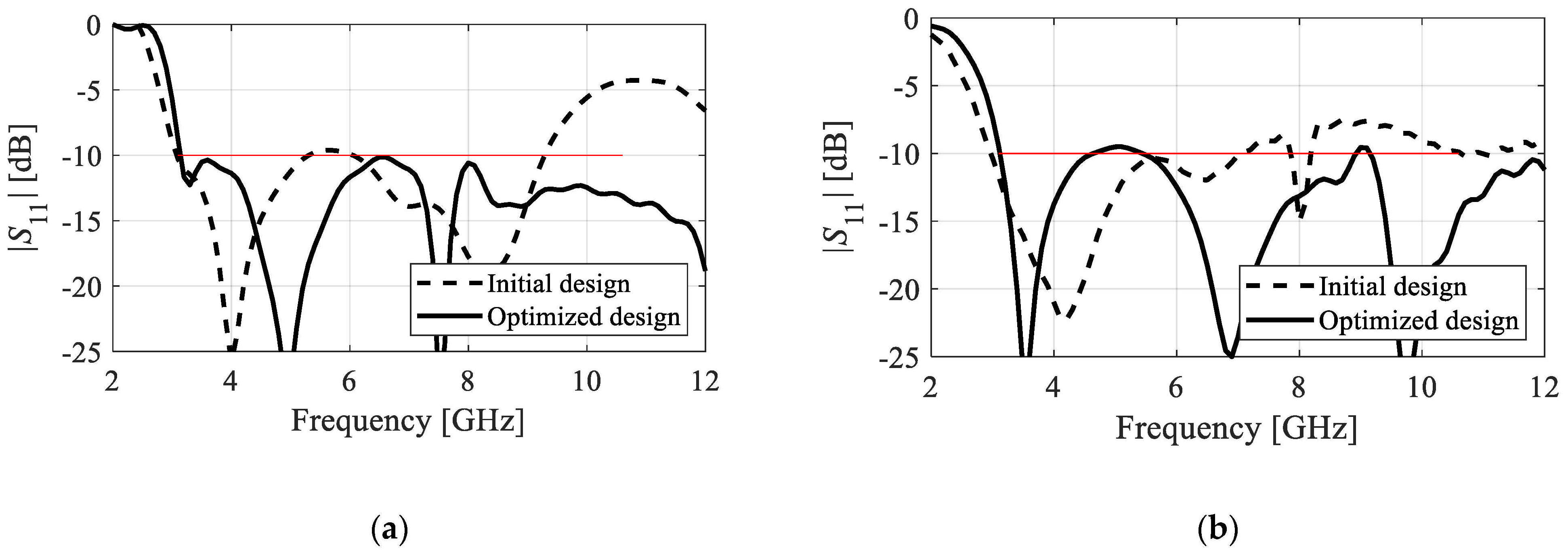
- Ensuring that the antenna reflection S11(x,f) does not exceed −10 dB within the operating frequency range F, i.e., |S11(x,f)| ≤ −10 dB for f ∈ F. The penalty function can be of a form c(x) = [(max{S(x) + 10,0})/10]2, where S(x) = max{f ∈ F: |S11(x,f)|}. Here, the utilization of the second power ensures smoothness of UP at the feasible region boundary. The latter is important as most constraints are active at the optimum design. In general, adjusting the power factor allows for controlling the constraint ‘hardness’; the second power provides a certain leeway for small violations.
- Ensuring that the axial ratio AR(x,f) of a CP antenna does not exceed 3 dB within the operating range F, i.e., AR(x,f) ≤ 3 dB for f ∈ F. The penalty function can be of a form c(x) = [(max{AR(x) − 3,0})/3]2, where AR(x) = max{f ∈ F: AR(x,f)}.
2.2. Reference Algorithm: Trust-Region Gradient-Based Procedure
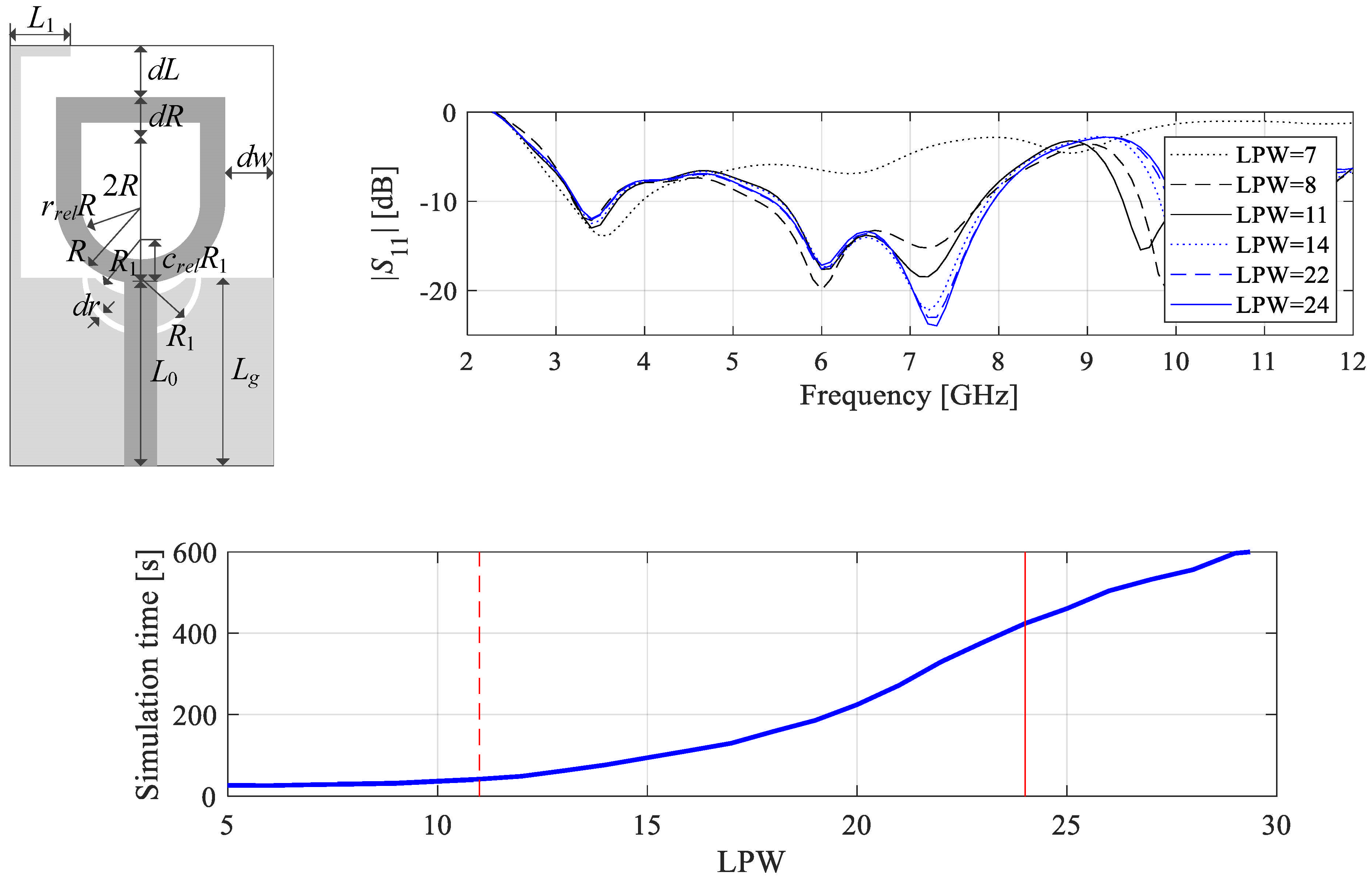
2.3. Multi-Fidelity Simulation Models
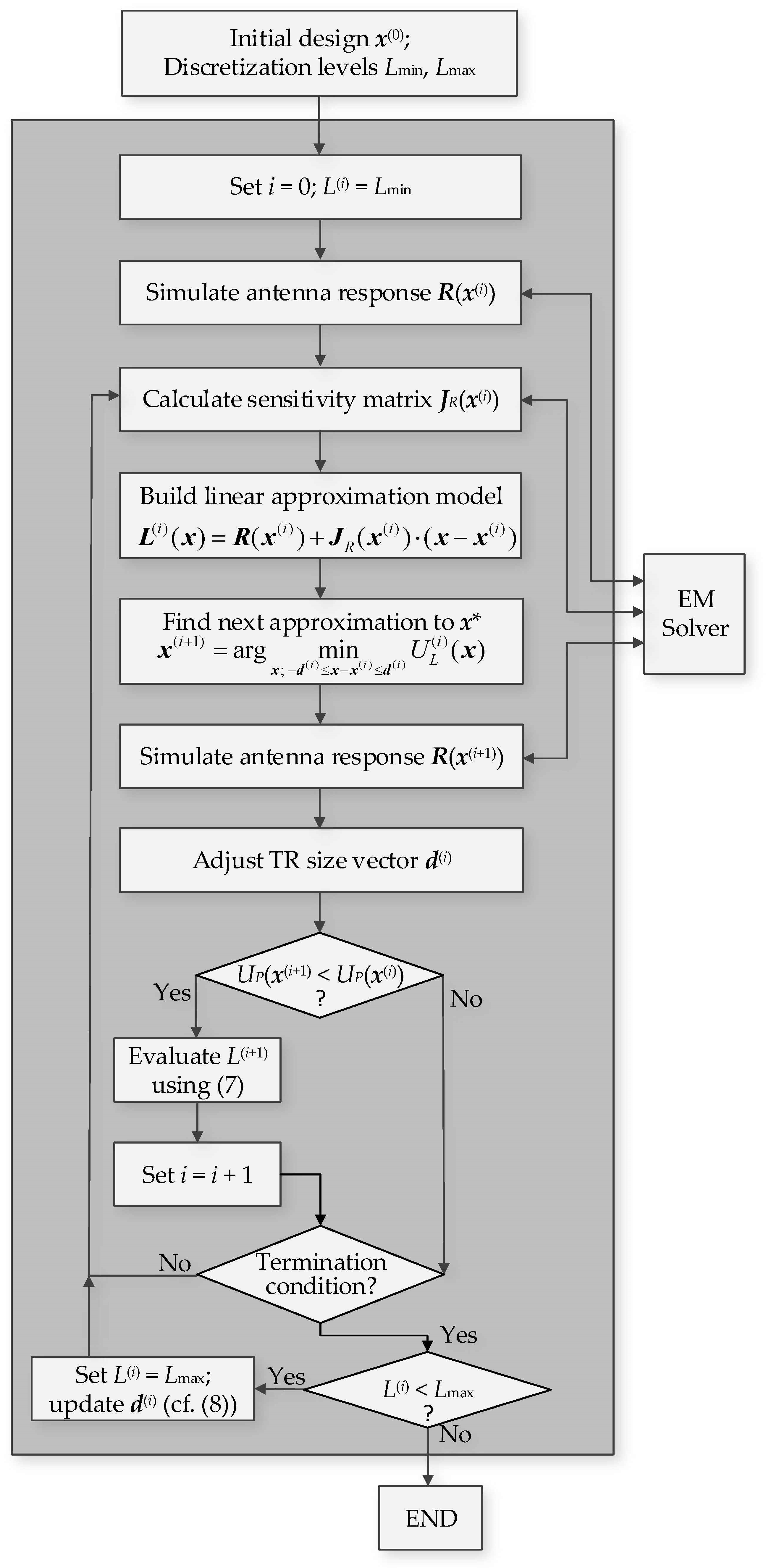
2.4. Model Management Scheme
- To enable a reduction of the computational cost of the algorithm, the optimization process should be initiated with the lowest-fidelity model;
- To ensure reliability of the process, the final stages of the algorithm should involve the high-fidelity model;
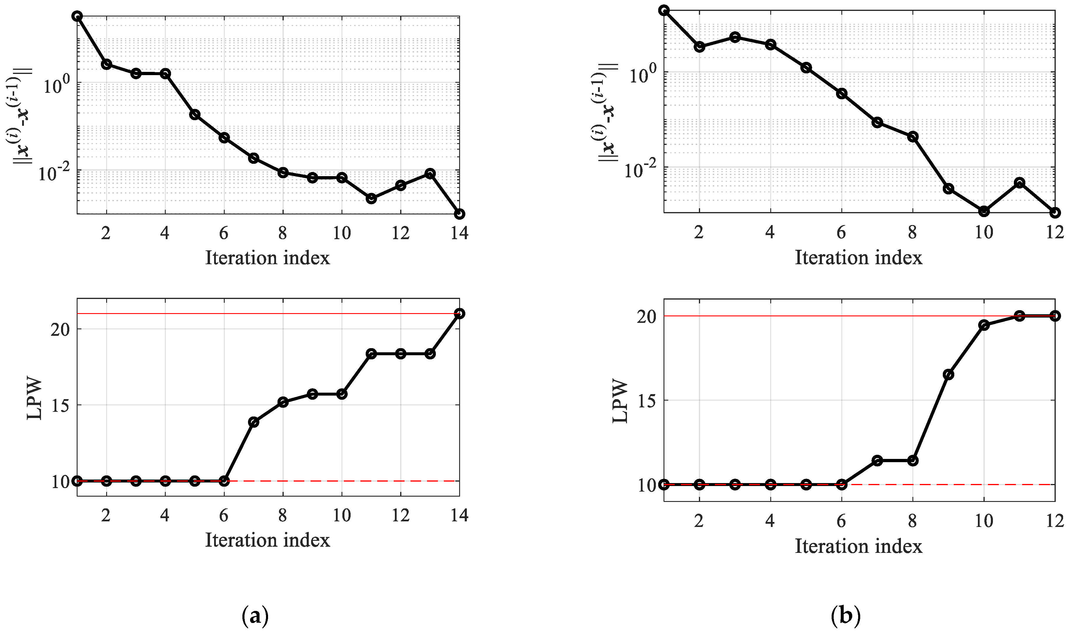
- The transition towards higher-fidelity models should be gradual and governed by the reliable factors that determine the optimization status, in particular the expected distance from the optimum. Here, we use the convergence status, measured by the distance between two subsequent iteration points ||x(i+1) − x(i)|| (convergence in argument), but also the improvement of the objective function value UP(x(i+1)) − UP(x(i)); reduction of both indicates that the optimization process is getting closer to termination;
- In order to facilitate the stability of the optimization process, the transition between the models of various fidelities should be possibly smooth with respect to the factors mentioned above.
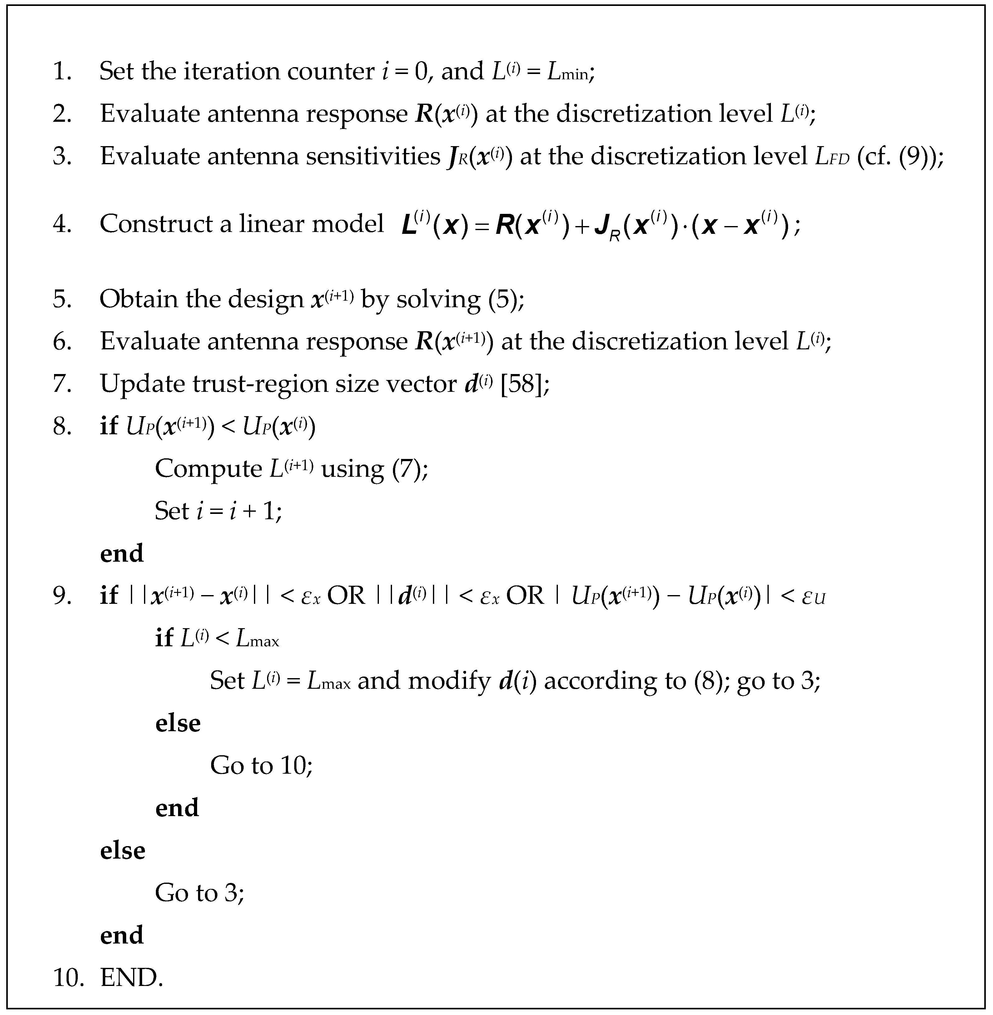
2.5. Optimization Algorithm
- εx, εU—algorithm termination thresholds, decided upon based on the required resolution of the optimization procedure (Section 2.4);
- M—threshold for initiating discretization level increase (Section 2.4);
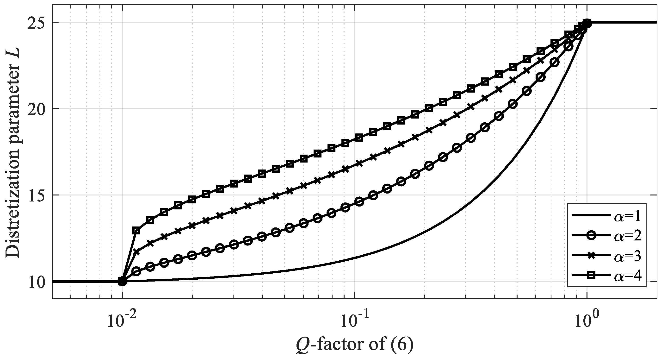
- α—shape parameter of the discretization level profile (Section 2.4);
- λ—parameter for setting discretization level LFD for sensitivity estimation, cf. (10);
- Md—trust-region size multiplication factor (cf. (8)).
3. Demonstration Case Studies and Benchmarking
3.1. Benchmark Antennas
3.2. Experimental Setup
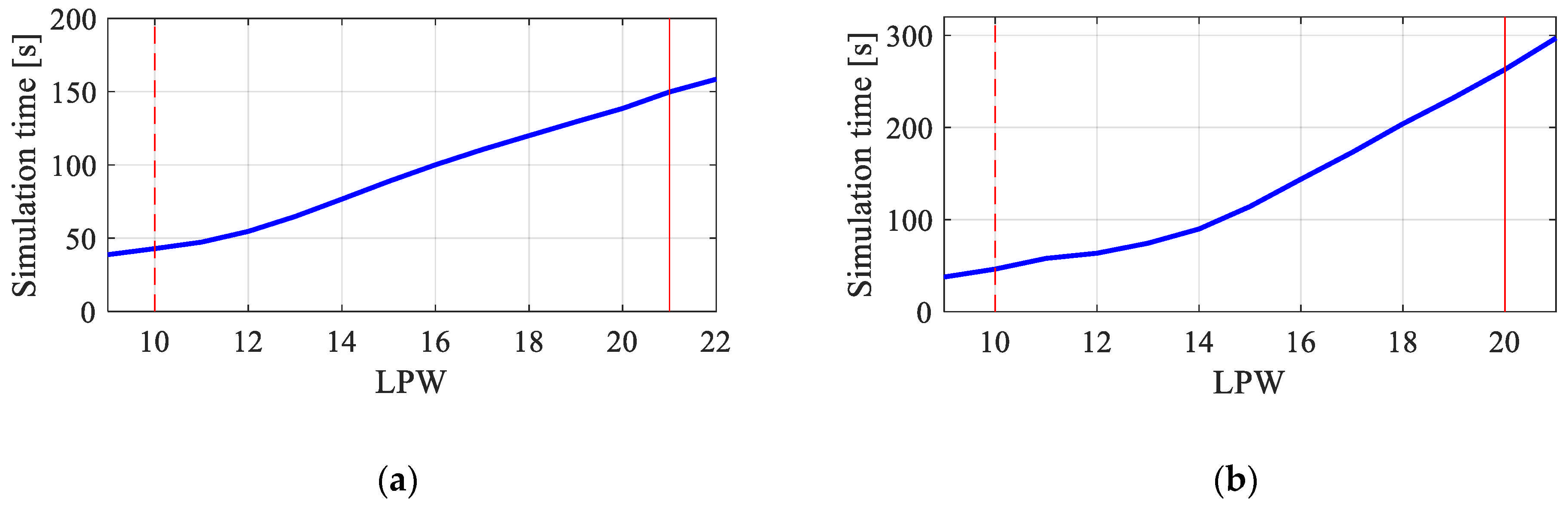
- Computational cost of the optimization process expressed in terms of the equivalent number of high-fidelity EM simulations of the antenna structure at hand; in the case of multi-fidelity algorithm, the simulation times of the model at a given level of fidelity are recalculated into the equivalent number of high-fidelity analyzes using the curves presented in Figure 6;
- Design quality measures as the average antenna footprint at the optimized design;
- Repeatability of results measures by means of the standard deviation of the obtained antenna footprint area. Clearly, the standard deviation will be positive even for the reference algorithm due to the aforementioned multimodality; consequently, the potential quality degradation should be considered as compared to the respective figures for the reference algorithm rather than to the zero value.
3.3. Results and Discussion
4. Conclusions
Author Contributions
Funding
Acknowledgments
Conflicts of Interest
References
- Yang, Y.; Sun, B.; Guo, J. A low-cost, single-layer, dual circularly polarized antenna for millimeter-wave applications. IEEE Ant. Wirel. Prop. Lett. 2019, 184, 651–655. [Google Scholar] [CrossRef]
- Bilgic, M.M.; Yegin, K. Modified annular ring antenna for GPS and SDARS automotive applications. IEEE Ant. Wirel. Prop. Lett. 2016, 15, 1442–1445. [Google Scholar] [CrossRef]
- Mobashsher, A.T.; Pretorius, A.J.; Abbosh, A.M. Low-profile vertical polarized slotted antenna for on-road RFID-enabled intelligent parking. IEEE Trans. Ant. Propag. 2020, 68, 527–532. [Google Scholar] [CrossRef]
- Qian, J.; Chen, F.; Xiang, K.; Chu, Q. Resonator-loaded multi-band microstrip slot antennas with bidirectional radiation patterns. IEEE Trans. Ant. Propag. 2019, 67, 6661–6666. [Google Scholar] [CrossRef]
- Liu, J.; Su, T.; Liu, Z. High-gain grating antenna with surface wave launcher array. IEEE Ant. Wirel. Prop. Lett. 2018, 17, 706–709. [Google Scholar] [CrossRef]
- Huang, H.; Gao, S.; Lin, S.; Ge, L. A wideband water patch antenna with polarization diversity. IEEE Ant. Wirel. Prop. Lett. 2020, 19, 1113–1117. [Google Scholar] [CrossRef]
- Yang, X.; Ge, L.; Ji, Y.; Zeng, X.; Luk, K.M. Design of low-profile multi-band half-mode substrate-integrated waveguide antennas. IEEE Trans. Ant. Propag. 2019, 67, 6639–6644. [Google Scholar] [CrossRef]
- Yang, H.; Fan, Y.; Liu, X. A compact dual-band stacked patch antenna with dual circular polarizations for BeiDou navigation satellite systems. IEEE Ant. Wirel. Prop. Lett. 2019, 18, 1472–1476. [Google Scholar] [CrossRef]
- Jha, K.R.; Bukhari, B.; Singh, C.; Mishra, G.; Sharma, S.K. Compact planar multistandard MIMO antenna for IoT applications. IEEE Trans. Ant. Propag. 2018, 66, 3327–3336. [Google Scholar] [CrossRef]
- Xue, K.; Yang, D.; Guo, C.; Zhai, H.; Li, H.; Zeng, Y. A dual-polarized filtering base-station antenna with compact size for 5G applications. IEEE Ant. Wirel. Prop. Lett. 2020, 19, 1316–1320. [Google Scholar] [CrossRef]
- Agneessens, S.; Lemey, S.; Vervust, T.; Rogier, H. Wearable, small, and robust: The circular quarter-mode textile antenna. IEEE Ant. Wirel. Prop. Lett. 2015, 14, 1482–1485. [Google Scholar] [CrossRef]
- Alqadami, A.S.M.; Nguyen-Trong, N.; Mohammed, B.; Stancombe, A.E.; Heitzmann, M.T.; Abbosh, A. Compact unidirectional conformal antenna based on flexible high-permittivity custom-made substrate for wearable wideband electromagnetic head imaging system. IEEE Trans. Ant. Propag. 2020, 68, 183–194. [Google Scholar] [CrossRef]
- Pandit, S.; Mohan, A.; Ray, P. Compact frequency-reconfigurable MIMO antenna for microwave sensing applications in WLAN and WiMAX frequency bands. IEEE Sens. Lett. 2008, 2, 1–4. [Google Scholar] [CrossRef]
- Pires, N.; Parra, T.; Skrivervik, A.K.; Moreira, A.A. Design and measurement of a differential printed antenna for a wireless sensor network node. IEEE Ant. Wirel. Prop. Lett. 2017, 16, 2228–2231. [Google Scholar] [CrossRef]
- Roshna, T.K.; Deepak, U.; Sajitha, V.R.; Vasudevan, K.; Mohanan, P. A compact UWB MIMO antenna with reflector to enhance isolation. IEEE Trans. Ant. Propag. 2015, 63, 1873–1877. [Google Scholar] [CrossRef]
- Koziel, S.; Cheng, Q.S.; Li, S. Optimization-driven antenna design framework with multiple performance constraints. Int. J. RF Microw. CAE 2018, 28, e21208. [Google Scholar] [CrossRef]
- Liu, J.; Esselle, K.P.; Hay, S.G.; Zhong, S. Effects of printed UWB antenna miniaturization on pulse fidelity and pattern stability. IEEE Trans. Ant. Prop. 2014, 62, 3903–3910. [Google Scholar] [CrossRef]
- Haq, M.A.; Koziel, S. Feedline alterations for optimization-based design of compact super wideband MIMO antennas in parallel configuration. IEEE Ant. Wirel. Prop. Lett. 2019, 18, 1986–1990. [Google Scholar]
- Reddy, V.V.; Sarma, N.V.S.N. Compact circularly polarized asymmetrical fractal boundary microstrip antenna for wireless applications. IEEE Ant. Wirel. Prop. Lett. 2014, 13, 118–121. [Google Scholar] [CrossRef]
- Haq, M.A.; Koziel, S. Ground plane alterations for design of high-isolation compact wideband MIMO antenna. IEEE Access 2018, 6, 48978–48983. [Google Scholar] [CrossRef]
- Teni, G.; Zhang, N.; Qiu, J.; Zhang, P. Research on a novel miniaturized antipodal Vivaldi antenna with improved radiation. IEEE Ant. Wirel. Prop. Lett. 2013, 12, 417–420. [Google Scholar] [CrossRef]
- Ren, J.; Hu, W.; Yin, Y.; Fan, R. Compact printed MIMO antenna for UWB applications. IEEE Ant. Wirel. Prop. Lett. 2014, 13, 1517–1520. [Google Scholar]
- Qin, X.; Li, Y. Compact dual-polarized cross-slot antenna with colocated feeding. IEEE Trans. Ant. Propag. 2019, 67, 7139–7143. [Google Scholar] [CrossRef]
- Tu, W.H.; Hsu, W.H.; Chang, K. Compact 5.8-GHz rectenna using stepped-impedance dipole antenna. IEEE Ant. Wirel. Prop. Lett. 2007, 6, 282–284. [Google Scholar] [CrossRef]
- Tao, J.; Feng, Q. Compact ultrawideband MIMO antenna with half-slot structure. IEEE Ant. Wirel. Prop. Lett. 2017, 16, 792–795. [Google Scholar] [CrossRef]
- Reddy, B.R.S.; Vakula, D. Compact zigzag-shaped-slit microstrip antenna with circular defected ground structure for wireless applications. IEEE Ant. Wirel. Prop. Lett. 2015, 14, 678–681. [Google Scholar] [CrossRef]
- Prajapati, P.R.; Murthy, G.G.K.; Patnaik, A.; Kartikeyan, M.V. Design and testing of a compact circularly polarised microstrip antenna with fractal defected ground structure for L-band applications. IET Microw. Ant. Prop. 2015, 9, 1179–1185. [Google Scholar] [CrossRef]
- Park, J.P.; Han, S.M.; Itoh, T. A rectenna design with harmonic-rejecting circular-sector antenna. IEEE Ant. Wirel. Prop. Lett. 2004, 3, 52–54. [Google Scholar] [CrossRef]
- Dahlan, A.; Kamarudin, M.R. Shorted microstrip patch antenna with parasitic element. J. Electr. Waves. Appl. 2010, 24, 327–339. [Google Scholar] [CrossRef]
- Kasgari, M.A.; Rahim, S.K.A.; Khalily, M. Two segments compact dielectric resonator antenna for UWB application. IEEE Ant. Wirel. Prop. Lett. 2012, 1, 1533–1536. [Google Scholar]
- Haq, M.A.; Koziel, S.; Cheng, Q.S. Miniaturization of wideband antennas by means of feed line topology alterations. IET Microw. Ant. Prop. 2018, 12, 2128–2134. [Google Scholar] [CrossRef]
- Haq, M.A.; Koziel, S. Quantitative assessment of wideband antenna geometry modifications for size-reduction-oriented design. AEU Int. J. Electr. Comm. 2018, 90, 45–52. [Google Scholar] [CrossRef]
- Kim, S.; Nam, S. Compact ultrawideband antenna on folded ground plane. IEEE Trans. Ant. Propag. 2020, 68, 7179–7183. [Google Scholar] [CrossRef]
- Cui, Y.; Luo, P.; Gong, Q.; Li, R. A compact tri-band horizontally polarized omnidirectional antenna for UAV applications. IEEE Ant. Wirel. Prop. Lett. 2019, 18, 601–605. [Google Scholar] [CrossRef]
- Johanesson, D.O.; Koziel, S. Feasible space boundary search for improved optimization-based miniaturization of antenna structures. IET Microw. Ant. Prop. 2018, 12, 1273–1278. [Google Scholar] [CrossRef]
- Johanesson, D.O.; Koziel, S.; Bekasiewicz, A. EM-driven constrained miniaturization of antennas using adaptive in-band reflection acceptance threshold. Int. J. Numer. Model. 2019, 32, e2513. [Google Scholar] [CrossRef]
- Koziel, S. Objective relaxation algorithm for reliable simulation-driven size reduction of antenna structure. IEEE Ant. Wirel. Prop. Lett. 2017, 16, 1949–1952. [Google Scholar] [CrossRef]
- Tomasson, J.A.; Koziel, S.; Pietrenko-Dabrowska, A. Quasi-global optimization of antenna structures using principal components and affine subspace-spanned surrogates. IEEE Access 2020, 8, 50078–50084. [Google Scholar] [CrossRef]
- Kolda, T.G.; Lewis, R.M.; Torczon, V. Optimization by direct search: New perspectives on some classical and modern methods. SIAM Rev. 2003, 45, 385–482. [Google Scholar] [CrossRef]
- Lalbakhsh, A.; Afzal, M.U.; Esselle, K.P. Multiobjective particle swarm optimization to design a time-delay equalizer metasurface for an electromagnetic band-gap resonator antenna. IEEE Ant. Wirel. Prop. Lett. 2017, 16, 915. [Google Scholar] [CrossRef]
- Zhao, W.J.; Liu, E.X.; Wang, B.; Gao, S.P.; Png, C.E. Differential evolutionary optimization of an equivalent dipole model for electromagnetic emission analysis. IEEE Trans. Electromagn. Comp. 2018, 60, 1635–1639. [Google Scholar] [CrossRef]
- Rajagopalan, H.; Kovitz, J.M.; Rahmat-Samii, Y. MEMS reconfigurable optimized E-shaped patch antenna design for cognitive radio. IEEE Trans. Ant. Propag. 2014, 62, 1056–1064. [Google Scholar] [CrossRef]
- Tziris, E.N.; Lazaridis, P.I.; Zaharis, Z.D.; Cosmas, J.P.; Mistry, K.K.; Glover, I.A. Optimized planar elliptical dipole antenna for UWB EMC applications. IEEE Trans. Electr. Comp. 2019, 61, 1377–1384. [Google Scholar] [CrossRef]
- Singh, U.; Rattan, M. Design of thinned concentric circular antenna arrays using firefly algorithm. IET Microw. Ant. Prop. 2014, 8, 894–900. [Google Scholar] [CrossRef]
- Koziel, S.; Ogurtsov, S.; Cheng, Q.S.; Bandler, J.W. Rapid EM-based microwave design optimization exploiting shape-preserving response prediction and adjoint sensitivities. IET Microw. Ant. Prop. 2014, 8, 775–781. [Google Scholar] [CrossRef]
- Hassan, E.; Noreland, D.; Augustine, R.; Wadbro, E.; Berggren, M. Topology optimization of planar antennas for wideband near-field coupling. IEEE Trans. Ant. Prop. 2015, 63, 4208–4213. [Google Scholar] [CrossRef]
- Koziel, S.; Pietrenko-Dabrowska, A. Expedited optimization of antenna input characteristics with adaptive Broyden updates. Eng. Comp. 2019, 37, 851–862. [Google Scholar] [CrossRef]
- Koziel, S.; Pietrenko-Dabrowska, A. Expedited feature-based quasi-global optimization of multi-band antennas with Jacobian variability tracking. IEEE Access 2020, 8, 83907–83915. [Google Scholar] [CrossRef]
- Cervantes-González, J.C.; Rayas-Sánchez, J.A.; López, C.A.; Camacho-Pérez, J.R.; Brito-Brito, Z.; Chávez-Hurtado, J.L. Space mapping optimization of handset antennas considering EM effects of mobile phone components and human body. Int. J. RF Microw. CAE 2016, 26, 121–128. [Google Scholar] [CrossRef]
- Koziel, S.; Ogurtsov, S. Antenna Design by Simulation—Driven Optimization; Springer: New York, NY, USA, 2014. [Google Scholar]
- Easum, J.A.; Nagar, J.; Werner, P.L.; Werner, D.H. Efficient multi-objective antenna optimization with tolerance analysis through the use of surrogate models. IEEE Trans. Ant. Prop. 2018, 66, 6706–6715. [Google Scholar] [CrossRef]
- Bandler, J.W.; Cheng, Q.S.; Dakroury, S.A.; Mohamed, A.S.; Bakr, M.H.; Madsen, K.; Sondergaard, J. Space mapping: The state of the art. IEEE Trans. Microw. Theory Tech. 2004, 52, 337–361. [Google Scholar] [CrossRef]
- Zhang, C.; Feng, F.; Gongal-Reddy, V.; Zhang, Q.J.; Bandler, J.W. Cognition-driven formulation of space mapping for equal-ripple optimization of microwave filters. IEEE Trans. Microw. Theory Techn. 2015, 63, 2154–2165. [Google Scholar] [CrossRef]
- Koziel, S.; Leifsson, L. Simulation—Driven Design by Knowledge—Based Response Correction Techniques; Springer: New York, NY, USA, 2016. [Google Scholar]
- Koziel, S.; Unnsteinsson, S.D. Expedited design closure of antennas by means of trust-region-based adaptive response scaling. IEEE Antennas Wirel. Prop. Lett. 2018, 17, 1099–1103. [Google Scholar] [CrossRef]
- Koziel, S. Fast simulation-driven antenna design using response-feature surrogates. Int. J. RF Microw. CAE 2015, 25, 394–402. [Google Scholar] [CrossRef]
- Koziel, S.; Ogurtsov, S.; Zieniutycz, W.; Sorokosz, L. Expedited design of microstrip antenna subarrays using surrogate-based optimization. IEEE Ant. Wirel. Prop. Lett. 2014, 13, 635–638. [Google Scholar] [CrossRef]
- Hassan, A.K.S.O.; Etman, A.S.; Soliman, E.A. Optimization of a novel nano antenna with two radiation modes using kriging surrogate models. IEEE Photonic J. 2018, 10, 4800807. [Google Scholar] [CrossRef]
- Barmuta, P.; Ferranti, F.; Gibiino, G.P.; Lewandowski, A.; Schreurs, D.M.M.P. Compact behavioral models of nonlinear active devices using response surface methodology. IEEE Trans. Microw. Theory Tech. 2015, 63, 56–64. [Google Scholar] [CrossRef]
- Rawat, A.; Yadav, R.N.; Shrivastava, S.C. Neural network applications in smart antenna arrays: A review. AEU Int. J. Elec. Comm. 2012, 66, 903–912. [Google Scholar] [CrossRef]
- Petrocchi, A.; Kaintura, A.; Avolio, G.; Spina, D.; Dhaene, T.; Raffo, A.; Schreurs, D.M.P.-P. Measurement uncertainty propagation in transistor model parameters via polynomial chaos expansion. IEEE Microw. Wirel. Comp. Lett. 2017, 27, 572–574. [Google Scholar] [CrossRef] [Green Version]
- Cai, J.; King, J.; Yu, C.; Liu, J.; Sun, L. Support vector regression-based behavioral modeling technique for RF power transistors. IEEE Microw. Wirel. Comp. Lett. 2018, 28, 428–430. [Google Scholar] [CrossRef]
- De Villiers, D.I.L.; Couckuyt, I.; Dhaene, T. Multi-objective optimization of reflector antennas using kriging and probability of improvement. In Proceedings of the 2017 IEEE International Symposium on Antennas and Propagation & USNC/URSI National Radio Science Meeting, San Diego, CA, USA, 9–14 July 2017. [Google Scholar]
- Tak, J.; Kantemur, A.; Sharma, Y.; Xin, H. A 3-D-printed W-band slotted waveguide array antenna optimized using machine learning. IEEE Ant. Wirel. Prop. Lett. 2018, 17, 2008–2012. [Google Scholar] [CrossRef]
- Koziel, S.; Pietrenko-Dabrowska, A. Performance—Driven Surrogate Modeling of High—Frequency Structures; Springer: New York, NY, USA, 2020. [Google Scholar]
- Koziel, S.; Mosler, F.; Reitzinger, S.; Thoma, P. Robust microwave design optimization using adjoint sensitivity and trust regions. Int. J. RF Microw. CAE 2012, 22, 10–19. [Google Scholar] [CrossRef]
- Koziel, S.; Pietrenko-Dabrowska, A. Reduced-cost electromagnetic-driven optimization of antenna structures by means of trust-region gradient-search with sparse Jacobian updates. IET Microw. Ant. Prop. 2019, 13, 1646–1652. [Google Scholar] [CrossRef]
- Koziel, S.; Unnsteinsson, S.D.; Bekasiewicz, A. Low-fidelity model considerations for simulation-based optimization of miniaturized wideband antennas. IET Microw. Ant. Prop. 2018, 12, 1613–1619. [Google Scholar] [CrossRef]
- Koziel, S.; Ogurtsov, S. Model management for cost-efficient surrogate-based optimization of antennas using variable-fidelity electromagnetic simulations. IET Microw. Ant. Prop. 2012, 6, 1643–1650. [Google Scholar] [CrossRef]
- Ullah, U.; Koziel, S.; Mabrouk, I.B. Rapid re-design and bandwidth/size trade-offs for compact wideband circular polarization antennas using inverse surrogates and fast EM-based parameter tuning. IEEE Trans. Ant. Prop. 2019, 68, 81–89. [Google Scholar] [CrossRef]
- Conn, A.R.; Gould, N.I.M.; Toint, P.L. Trust Region Methods; MPS-SIAM Series on Optimization: Philadelphia, PA, USA, 2000. [Google Scholar]
- Su, Y.; Li, J.; Fan, Z.; Chen, R. Shaping optimization of double reflector antenna based on manifold mapping. In Proceedings of the 2017 International Applied Computational Electromagnetics Society Symposium (ACES 2017), Suzhou, China, 1–2 August 2017. [Google Scholar]
- Liu, B.; Koziel, S.; Ali, N. SADEA-II: A generalized method for efficient global optimization of antenna design. J. Comp. Design Eng. 2017, 4, 86–97. [Google Scholar] [CrossRef]
- Koziel, S.; Bekasiewicz, A.; Couckuyt, I.; Dhaene, T. Efficient multi-objective simulation-driven antenna design using co-kriging. IEEE Trans. Antennas Prop. 2014, 62, 5900–5905. [Google Scholar] [CrossRef]
- Jacobs, J.P.; Koziel, S. Two-stage framework for efficient Gaussian process modeling of antenna input characteristics. IEEE Trans. Antennas Prop. 2014, 62, 706–713. [Google Scholar] [CrossRef] [Green Version]
- Alsath, M.G.N.; Kanagasabai, M. Compact UWB monopole antenna for automotive communications. IEEE Trans. Ant. Prop. 2015, 63, 4204–4208. [Google Scholar] [CrossRef]
- Koziel, S.; Bekasiewicz, A. Low-cost multi-objective optimization of antennas using Pareto front exploration and response features. In Proceedings of the 2016 IEEE International Symposium on Antennas and Propagation (APSURSI 2016), Fajardo, Puerto Rico, 26 June–1 July 2016. [Google Scholar]
- Haq, M.A.; Koziel, S. Simulation-based optimization for rigorous assessment of ground plane modifications in compact UWB antenna design. Int. J. RF Microw. CAE 2018, 28, e21204. [Google Scholar] [CrossRef]


| Antenna | Substrate | Designable Parameters (mm) | Other Parameters (mm) |
|---|---|---|---|
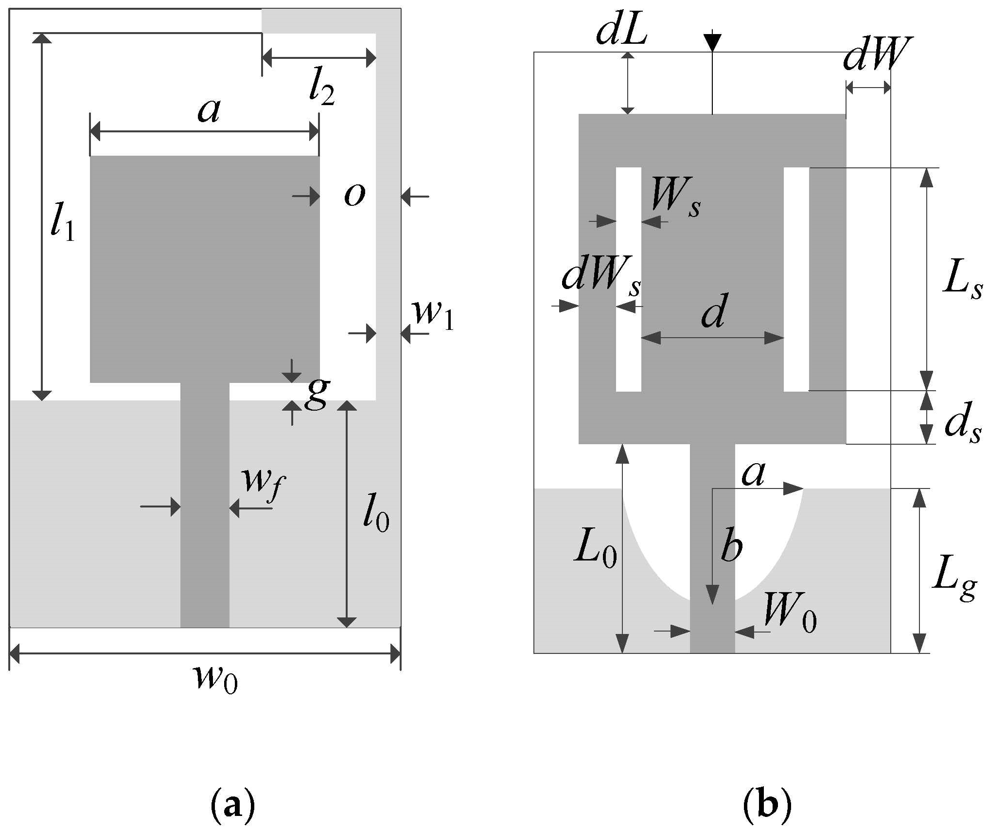
| I [77] | RF-35 (εr = 3.5, h = 0.762 mm) | x = [l0 g a l1 l2 w1 o]T | w0 = 2o + a, wf = 1.7 |
| II [78] | FR4 (εr = 4.3, h = 1.55 mm) | x = [Lg L0 Ls Ws d dL ds dWs dW a b]T | W0 = 3.0 |
| Antenna | Lowest-Fidelity Model | High-Fidelity Model | ||
|---|---|---|---|---|
| Lmin | Simulation Time [s] | Lmax | Simulation Time [s] | |
| I | 10 | 42 | 21 | 150 |
| II | 10 | 46 | 20 | 265 |
| Algorithm | Performance Figure | ||||
|---|---|---|---|---|---|
| Cost 1 | Cost Savings 2 | Footprint Area A (mm2) 3 | ΔA (mm2) 4 | Std(A) (mm2) 5 | |
| Conventional TR search | 106.8 | - | 308.2 | - | 37.2 |
| Multi-fidelity (this work) | 34.7 | 67.5% | 310.5 | 2.3 | 41.3 |
| Algorithm | Performance Figure | ||||
|---|---|---|---|---|---|
| Cost 1 | Cost Savings 2 | Footprint Area A (mm2) 3 | ΔA (mm2) 4 | Std(A) (mm2) 5 | |
| Conventional TR search | 164.9 | - | 212.8 | - | 14.2 |
| Multi-fidelity (this work) | 39.4 | 76.1% | 209.1 | −3.7 | 5.6 |
Publisher’s Note: MDPI stays neutral with regard to jurisdictional claims in published maps and institutional affiliations. |
© 2021 by the authors. Licensee MDPI, Basel, Switzerland. This article is an open access article distributed under the terms and conditions of the Creative Commons Attribution (CC BY) license (https://creativecommons.org/licenses/by/4.0/).
Share and Cite
Pietrenko-Dabrowska, A.; Koziel, S. Cost-Efficient EM-Driven Size Reduction of Antenna Structures by Multi-Fidelity Simulation Models. Electronics 2021, 10, 1536. https://doi.org/10.3390/electronics10131536
Pietrenko-Dabrowska A, Koziel S. Cost-Efficient EM-Driven Size Reduction of Antenna Structures by Multi-Fidelity Simulation Models. Electronics. 2021; 10(13):1536. https://doi.org/10.3390/electronics10131536
Chicago/Turabian StylePietrenko-Dabrowska, Anna, and Slawomir Koziel. 2021. "Cost-Efficient EM-Driven Size Reduction of Antenna Structures by Multi-Fidelity Simulation Models" Electronics 10, no. 13: 1536. https://doi.org/10.3390/electronics10131536
APA StylePietrenko-Dabrowska, A., & Koziel, S. (2021). Cost-Efficient EM-Driven Size Reduction of Antenna Structures by Multi-Fidelity Simulation Models. Electronics, 10(13), 1536. https://doi.org/10.3390/electronics10131536