
Memcapacitor and Meminductor Circuit Emulators: A Review

 ,
,  , ,
, ,  and
and 
Abstract
:1. Introduction
2. Memcapacitor Emulators
3. Meminductor Emulators
4. Universal Emulators: Memcapacitors and Meminductor
5. Conclusions
Author Contributions
Funding
Conflicts of Interest
References
- Chua, L. Memristor-The Missing Circuit Element. IEEE Trans. Circuit Theory 1971, 18, 507–519. [Google Scholar] [CrossRef]
- Chua, L.O.; Kang, S.M. Memristive Devices and Systems. Proc. IEEE 1976, 64, 209–223. [Google Scholar] [CrossRef]
- Chua, L.O.; Kocarev, L.; Eckert, K.; Itoh, M. Experimental Chaos Synchronization in Chua’s Circuit. Int. J. Bifurc. Chaos 1992, 2, 705–708. [Google Scholar] [CrossRef]
- Chua, L.O. State Space Theory of Nonlinear Two- Terminal Higher-Order Elements. J. Frankl. Inst. 1983, 316, 1–50. [Google Scholar] [CrossRef]
- Chua, L.O. Chua’s Circuit: An Overview Ten Years Later. J. Circuits Syst. Comput. 1994, 4, 117–159. [Google Scholar] [CrossRef]
- Süsse, R.; Domhardt, A.; Reinhard, M. Calculation of Electrical Circuits with Fractional Characteristics of Construction Elements. Forsch. Ing. 2005, 69, 230–235. [Google Scholar] [CrossRef]
- Strukov, D.B.; Snider, G.S.; Stewart, D.R.; Williams, R.S. The Missing Memristor Found. Nature 2008, 453, 80–83. [Google Scholar] [CrossRef]
- Jo, S.H.; Chang, T.; Ebong, I.; Bhadviya, B.B.; Mazumder, P.; Lu, W. Nanoscale Memristor Device as Synapse in Neuromorphic Systems. Nano Lett. 2010, 10, 1297–1301. [Google Scholar] [CrossRef] [PubMed]
- Pershin, Y.V.; Di Ventra, M. Experimental Demonstration of Associative Memory with Memristive Neural Networks. Neural Netw. 2010, 23, 881–886. [Google Scholar] [CrossRef] [Green Version]
- Azghadi, M.R.; Linares-Barranco, B.; Abbott, D.; Leong, P.H.W. A Hybrid CMOS-Memristor Neuromorphic Synapse. IEEE Trans. Biomed. Circuits Syst. 2017, 11, 434–445. [Google Scholar] [CrossRef] [Green Version]
- Prezioso, M.; Merrikh-Bayat, F.; Hoskins, B.D.; Adam, G.C.; Likharev, K.K.; Strukov, D.B. Training and Operation of an Integrated Neuromorphic Network Based on Metal-Oxide Memristors. Nature 2015, 521, 61–64. [Google Scholar] [CrossRef] [PubMed] [Green Version]
- Kozma, R.; Pino, R.E.; Pazienza, G.E. (Eds.) Advances in Neuromorphic Memristor Science and Applications; Springer: Dordrecht, The Netherlands, 2012; ISBN 978-94-007-4490-5. [Google Scholar]
- Shin, S.; Kim, K.; Kang, S. Memristor Applications for Programmable Analog ICs. IEEE Trans. Nanotechnol. 2011, 10, 266–274. [Google Scholar] [CrossRef]
- Merrikh-Bayat, F.; Shouraki, S.B. Memristor-Based Circuits for Performing Basic Arithmetic Operations. Procedia Comput. Sci. 2011, 3, 128–132. [Google Scholar] [CrossRef] [Green Version]
- Pershin, Y.V.; Ventra, M.D. Practical Approach to Programmable Analog Circuits With Memristors. IEEE Trans. Circuits Syst. I Regul. Pap. 2010, 57, 1857–1864. [Google Scholar] [CrossRef] [Green Version]
- Pershin, Y.V.; Sazonov, E.; Di Ventra, M. Analogue-to-Digital and Digital-to-Analogue Conversion with Memristive Devices. Electron. Lett. 2012, 48, 73. [Google Scholar] [CrossRef] [Green Version]
- Vourkas, I.; Sirakoulis, G.C. Emerging Memristor-Based Logic Circuit Design Approaches: A Review. IEEE Circuits Syst. Mag. 2016, 16, 15–30. [Google Scholar] [CrossRef]
- Chen, S.; Mahmoodi, M.R.; Shi, Y.; Mahata, C.; Yuan, B.; Liang, X.; Wen, C.; Hui, F.; Akinwande, D.; Strukov, D.B.; et al. Wafer-Scale Integration of Two-Dimensional Materials in High-Density Memristive Crossbar Arrays for Artificial Neural Networks. Nat. Electron. 2020, 3, 638–645. [Google Scholar] [CrossRef]
- Yuan, B.; Liang, X.; Zhong, L.; Shi, Y.; Palumbo, F.; Chen, S.; Hui, F.; Jing, X.; Villena, M.A.; Jiang, L.; et al. 150 Nm × 200 Nm Cross-Point Hexagonal Boron Nitride-Based Memristors. Adv. Electron. Mater. 2020, 6, 1900115. [Google Scholar] [CrossRef]
- Zhu, K.; Liang, X.; Yuan, B.; Villena, M.A.; Wen, C.; Wang, T.; Chen, S.; Hui, F.; Shi, Y.; Lanza, M. Graphene–Boron Nitride–Graphene Cross-Point Memristors with Three Stable Resistive States. ACS Appl. Mater. Interfaces 2019, 11, 37999–38005. [Google Scholar] [CrossRef]
- Driscoll, T.; Quinn, J.; Klein, S.; Kim, H.T.; Kim, B.J.; Pershin, Y.V.; Di Ventra, M.; Basov, D.N. Memristive Adaptive Filters. Appl. Phys. Lett. 2010, 97, 093502. [Google Scholar] [CrossRef] [Green Version]
- Buscarino, A.; Fortuna, L.; Frasca, M.; Valentina Gambuzza, L. A Chaotic Circuit Based on Hewlett-Packard Memristor. Chaos 2012, 22, 023136. [Google Scholar] [CrossRef] [PubMed]
- Muthuswamy, B.; Kokate, P.P. Memristor-Based Chaotic Circuits. IETE Tech. Rev. 2009, 26, 417–429. [Google Scholar] [CrossRef] [Green Version]
- Xu, C.; Dong, X.; Jouppi, N.P.; Xie, Y. Design Implications of Memristor-Based RRAM Cross-Point Structures. In Proceedings of the 2011 Design, Automation Test in Europe, Grenoble, France, 14–18 March 2011; pp. 1–6. [Google Scholar]
- Secco, J.; Corinto, F.; Sebastian, A. Flux–Charge Memristor Model for Phase Change Memory. IEEE Trans. Circuits Syst. II Express Briefs 2018, 65, 111–114. [Google Scholar] [CrossRef]
- Almurib, H.A.F.; Kumar, T.N.; Lombardi, F. Design and Evaluation of a Memristor-Based Look-up Table for Non-Volatile Field Programmable Gate Arrays. IET Circuits Devices Syst. 2016, 10, 292–300. [Google Scholar] [CrossRef]
- Ting, Y.-H.; Chen, J.-Y.; Huang, C.-W.; Huang, T.-K.; Hsieh, C.-Y.; Wu, W.-W. Observation of Resistive Switching Behavior in Crossbar Core–Shell Ni/NiO Nanowires Memristor. Small 2018, 14, 1703153. [Google Scholar] [CrossRef] [PubMed]
- Miao, F.; Yi, W.; Goldfarb, I.; Yang, J.J.; Zhang, M.-X.; Pickett, M.D.; Strachan, J.P.; Medeiros-Ribeiro, G.; Williams, R.S. Continuous Electrical Tuning of the Chemical Composition of TaOx-Based Memristors. ACS Nano 2012, 6, 2312–2318. [Google Scholar] [CrossRef] [PubMed]
- Chen, Y.; Liu, G.; Wang, C.; Zhang, W.; Li, R.-W.; Wang, L. Polymer Memristor for Information Storage and Neuromorphic Applications. Mater. Horiz. 2014, 1, 489–506. [Google Scholar] [CrossRef]
- Zhang, L.; Gong, T.; Wang, H.; Guo, Z.; Zhang, H. Memristive Devices Based on Emerging Two-Dimensional Materials beyond Graphene. Nanoscale 2019, 11, 12413–12435. [Google Scholar] [CrossRef]
- Romero, F.J.; Toral, A.; Medina-Rull, A.; Moraila-Martinez, C.L.; Morales, D.P.; Ohata, A.; Godoy, A.; Ruiz, F.G.; Rodriguez, N. Resistive Switching in Graphene Oxide. Front. Mater. 2020, 7. [Google Scholar] [CrossRef] [Green Version]
- Romero, F.J.; Toral-Lopez, A.; Ohata, A.; Morales, D.P.; Ruiz, F.G.; Godoy, A.; Rodriguez, N. Laser-Fabricated Reduced Graphene Oxide Memristors. Nanomaterials 2019, 9, 897. [Google Scholar] [CrossRef] [Green Version]
- Sahu, D.P.; Jetty, P.; Jammalamadaka, S.N. Graphene Oxide Based Synaptic Memristor Device for Neuromorphic Computing. Nanotechnology 2021, 32, 155701. [Google Scholar] [CrossRef] [PubMed]
- Ventra, M.D.; Pershin, Y.V.; Chua, L.O. Circuit Elements With Memory: Memristors, Memcapacitors, and Meminductors. Proc. IEEE 2009, 97, 1717–1724. [Google Scholar] [CrossRef] [Green Version]
- Romero, F.J.; Escudero, M.; Medina-Garcia, A.; Morales, D.P.; Rodriguez, N. Meminductor Emulator Based on a Modified Antoniou’s Gyrator Circuit. Electronics 2020, 9, 1407. [Google Scholar] [CrossRef]
- Liang, Y.; Chen, H.; Yu, D.S. A Practical Implementation of a Floating Memristor-Less Meminductor Emulator. IEEE Trans. Circuits Syst. II Express Briefs 2014, 61, 299–303. [Google Scholar] [CrossRef]
- The Computer That Stores and Processes Information at the Same Time. Available online: https://www.technologyreview.com/2012/11/21/181520/the-computer-that-stores-and-processes-information-at-the-same-time/ (accessed on 15 May 2021).
- Pershin, Y.V.; Di Ventra, M. Memcomputing: A Computing Paradigm to Store and Process Information on the Same Physical Platform. In Proceedings of the 2014 International Workshop on Computational Electronics (IWCE), Paris, France, 3–6 June 2014; pp. 1–2. [Google Scholar]
- Di Ventra, M.; Pershin, Y.V. The Parallel Approach. Nat. Phys. 2013, 9, 200–202. [Google Scholar] [CrossRef]
- Fouda, M.E.; Radwan, A.G. Charge Controlled Memristor-Less Memcapacitor Emulator. Electron. Lett. 2012, 48, 1454–1455. [Google Scholar] [CrossRef]
- Biolek, D.; Biolek, Z.; Biolkova, V. SPICE Modelling of Memcapacitor. Electron. Lett. 2010, 46, 520–522. [Google Scholar] [CrossRef]
- Sah, M.P.; Yang, C.; Budhathoki, R.K.; Kim, H.; Yoo, H.J. Implementation of a Memcapacitor Emulator with Off-the-Shelf Devices. Elektron. Elektrotechnika 2013, 19, 54–58. [Google Scholar] [CrossRef]
- Romero, F.J.; Morales, D.P.; Godoy, A.; Ruiz, F.G.; Tienda-Luna, I.M.; Ohata, A.; Rodriguez, N. Memcapacitor Emulator Based on the Miller Effect. Int. J. Circuit Theory Appl. 2019, 47, 572–579. [Google Scholar] [CrossRef]
- Wang, X.Y.; Fitch, A.L.; Iu, H.H.C.; Qi, W.G. Design of a Memcapacitor Emulator Based on a Memristor. Phys. Lett. A 2012, 376, 394–399. [Google Scholar] [CrossRef]
- Pershin, Y.V.; Ventra, M.D. Emulation of Floating Memcapacitors and Meminductors Using Current Conveyors. Electron. Lett. 2011, 47, 243–244. [Google Scholar] [CrossRef] [Green Version]
- Yu, D.S.; Liang, Y.; Chen, H.; Iu, H.H.C. Design of a Practical Memcapacitor Emulator Without Grounded Restriction. IEEE Trans. Circuits Syst. II Express Briefs 2013, 60, 207–211. [Google Scholar] [CrossRef]
- Yesil, A.; Babacan, Y. Electronically Controllable Memcapacitor Circuit with Experimental Results. IEEE Trans. Circuits Syst. II Express Briefs 2021, 68, 1443–1447. [Google Scholar] [CrossRef]
- Vista, J.; Ranjan, A. Simple Charge Controlled Floating Memcapacitor Emulator Using DXCCDITA. Analog. Integr. Circuits Signal Process. 2020, 104, 37–46. [Google Scholar] [CrossRef]
- Wang, S.-F. The Gyrator for Transforming Nano Memristor into Meminductor. Circuit World 2016, 42, 197–200. [Google Scholar] [CrossRef]
- Romero, F.J.; Medina-Garcia, A.; Escudero, M.; Morales, D.P.; Rodriguez, N. Design and Implementation of a Floating Meminductor Emulator upon Riordan Gyrator. AEU Int. J. Electron. Commun. 2021, 133, 153671. [Google Scholar] [CrossRef]
- Sah, M.P.; Budhathoki, R.K.; Yang, C.; Kim, H. Mutator-Based Meminductor Emulator for Circuit Applications. Circuits Syst. Signal Process. 2014, 33, 2363–2383. [Google Scholar] [CrossRef]
- Sah, M.P.; Budhathoki, R.K.; Yang, C.; Kim, H. A Mutator-Based Meminductor Emulator Circuit. In Proceedings of the 2014 IEEE International Symposium on Circuits and Systems (ISCAS), Melbourne, VIC, Australia, 1–5 June 2014; pp. 2249–2252. [Google Scholar]
- Liang, Y.; Ying, S.; Bingmeng, H.; Lu, C.; Jing, S. Design and Characteristic Analysis of Floating Flux-Controlled Meminductor Emulator. J. Syst. Simul. 2018, 30, 1337. [Google Scholar] [CrossRef]
- Sozen, H.; Cam, U. A Novel Floating/Grounded Meminductor Emulator. J. Circuits Syst. Comput. 2020, 29, 2050247. [Google Scholar] [CrossRef]
- Fouda, M.E.; Radwan, A.G. Memristor-Less Current- and Voltage-Controlled Meminductor Emulators. In Proceedings of the 2014 21st IEEE International Conference on Electronics, Circuits and Systems (ICECS), Marseille, France, 7–10 December 2014; pp. 279–282. [Google Scholar]
- Elwakil, A.S.; Fouda, M.E.; Radwan, A.G. A Simple Model of Double-Loop Hysteresis Behavior in Memristive Elements. IEEE Trans. Circuits Syst. II Express Briefs 2013, 60, 487–491. [Google Scholar] [CrossRef]
- Konal, M.; Kacar, F. Electronically Tunable Meminductor Based on OTA. AEU Int. J. Electron. Commun. 2020, 126, 153391. [Google Scholar] [CrossRef]
- Vista, J.; Ranjan, A. High Frequency Meminductor Emulator Employing VDTA and Its Application. IEEE Trans. Comput. Aided Des. Integr. Circuits Syst. 2020, 39, 2020–2028. [Google Scholar] [CrossRef]
- Babacan, Y. An Operational Transconductance Amplifier-Based Memcapacitor and Meminductor. Istanb. Univ. J. Electr. Electron. Eng. 2018, 18, 36–38. [Google Scholar] [CrossRef]
- Çam Taşkıran, Z.G.; Sağbaş, M.; Ayten, U.E.; Sedef, H. A New Universal Mutator Circuit for Memcapacitor and Meminductor Elements. AEU Int. J. Electron. Commun. 2020, 119, 153180. [Google Scholar] [CrossRef]
- Yu, D.; Liang, Y.; Iu, H.H.C.; Chua, L.O. A Universal Mutator for Transformations Among Memristor, Memcapacitor, and Meminductor. IEEE Trans. Circuits Syst. II Express Briefs 2014, 61, 758–762. [Google Scholar] [CrossRef]
- Yu, D.; Zhao, X.; Sun, T.; Iu, H.H.C.; Fernando, T. A Simple Floating Mutator for Emulating Memristor, Memcapacitor, and Meminductor. IEEE Trans. Circuits Syst. II Express Briefs 2020, 67, 1334–1338. [Google Scholar] [CrossRef]
- Zhao, Q.; Wang, C.; Zhang, X. A Universal Emulator for Memristor, Memcapacitor, and Meminductor and Its Chaotic Circuit. Chaos 2019, 29, 013141. [Google Scholar] [CrossRef]


| Reference | Mutator | Configuration | Control Variable | Key Components | Experimental |
|---|---|---|---|---|---|
| Fouda and Radwan [40] | No | Grounded | Charge | Op amps Analog multiplier Copy of the input current | No |
| Sah et al. [42] | No | Grounded | Charge | Op amps Analog multiplier | Yes |
| Romero et al. [43] | Yes | Grounded | Voltage | Op amps Memristor 1 | Yes |
| Wang et al. [44] | Yes | Grounded | Voltage | Current conveyors Memristor 1 | Yes |
| Pershin and Di Ventra [45] | Yes | Floating | Voltage | Current conveyors Inductor Memristor | No |
| Yesil and Babacan [47] | No | Grounded | Charge | Current conveyor OTA Analog multiplier | Yes |
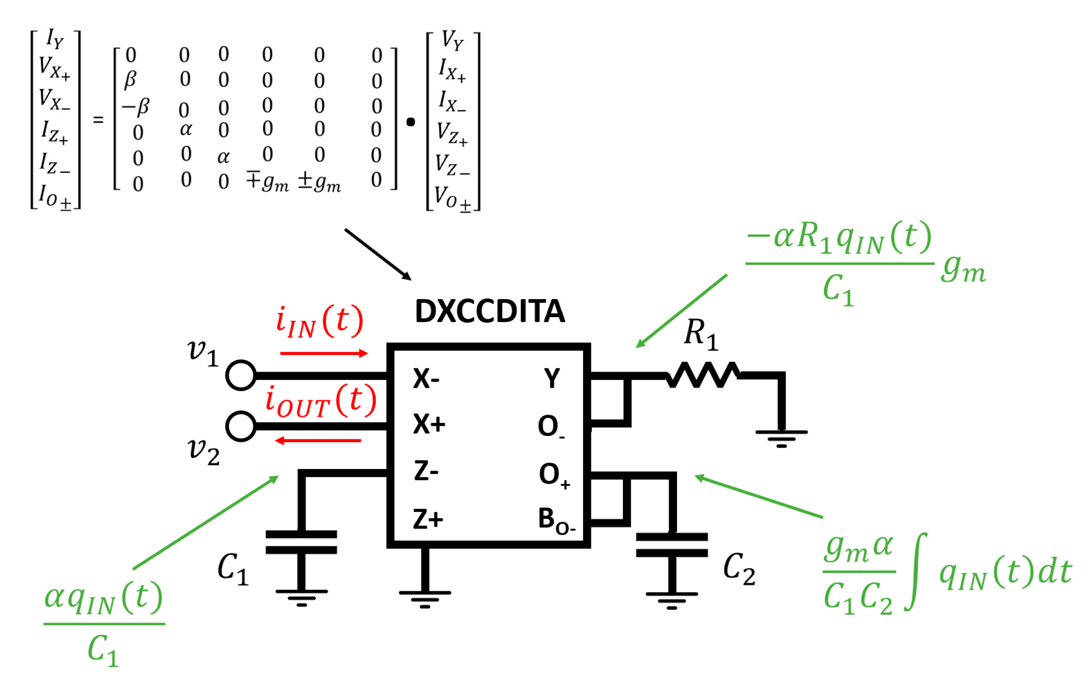
| Vista and Ranjan [48] | No | Floating | Charge | Custom DXCCDITA | No |
| Reference | Mutator | Configuration | Control Variable | Key Components | Experimental |
|---|---|---|---|---|---|
| Wang [49] | Yes | Grounded | Flux | Op amps, Memristor 1 | No |
| Romero et al. [35] | Yes | Grounded | Flux | Op amps, Memristor | No |
| Romero et al. [50] | Yes | Floating | Flux | Op amps, Memristor | Yes |
| Sah et al. [51] | Yes | Grounded | Flux | Current conveyor, Op amps, Memristor 1 | Yes |
| Sha et al. [52] | Yes | Grounded | Flux | Current conveyors, Memristor | No |
| Liang et al. [36] | Yes | Floating | Flux | Current conveyor, Op amps, Memristor | Yes |
| Fouda and Radwan [55] | No | Grounded | Current | Current conveyor, Analog multiplier, Adder | No |
| Reference | Emulator | Mutator | Conf. | Control Variable | Key Components | Experimental |
|---|---|---|---|---|---|---|
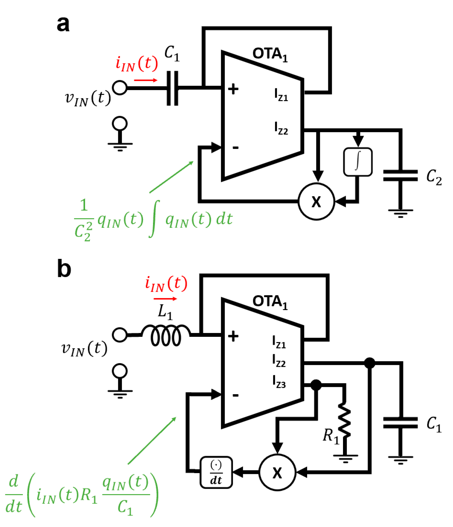
| Babacan [59] | Memcap. | No | Grounded | Charge | OTA Integrator Differentiator Multiplier | No |
| Memind. | Current | |||||
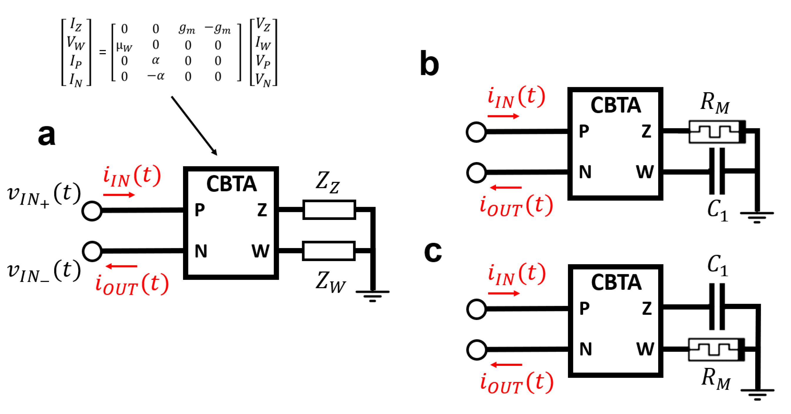
| Taşkiran et al. [60] | Memcap. | Yes | Floating | Voltage | Custom CBTA Memristor 1 | No |
| Memind. | Flux | |||||
| Yu et al. [61] | Memcap. | Yes | Grounded | Voltage | Current Conveyor Memristor | Yes |
| Memind. | Flux | |||||
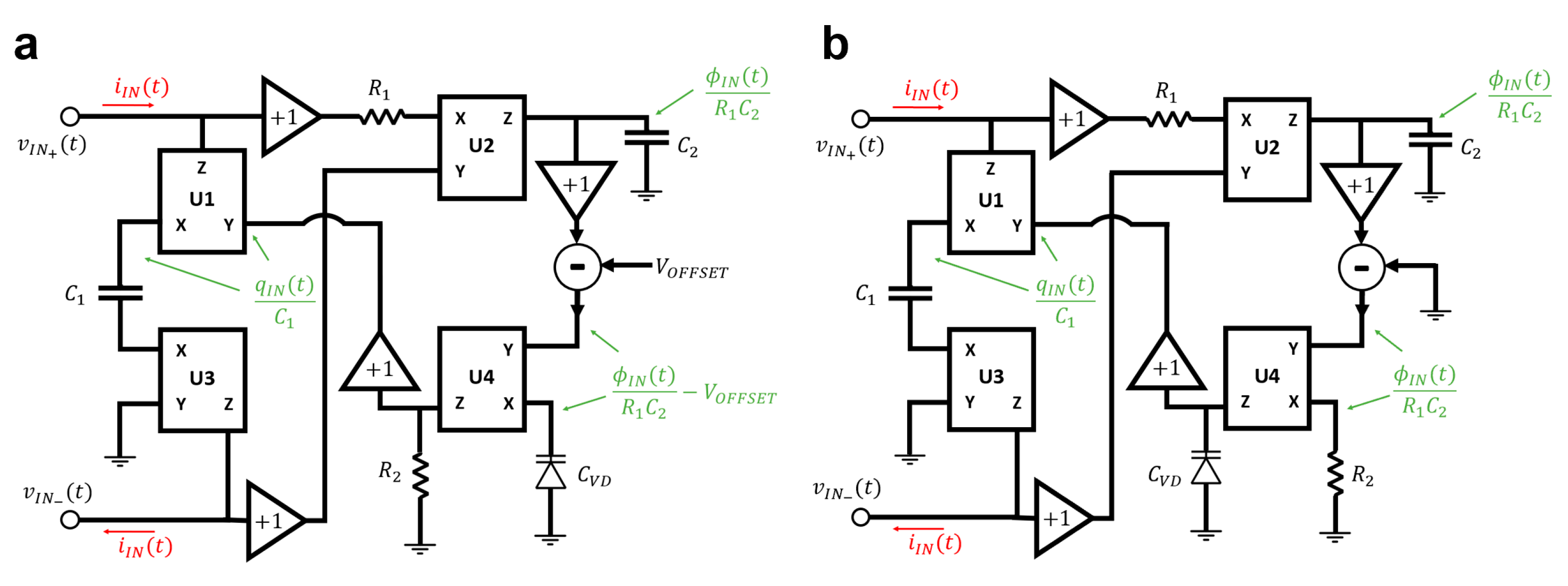
| Yu et al. [62] | Memcap. | No | Floating | Voltage | Current Conveyor Varactor diode Subtractor | Yes |
| Memind. | Flux | |||||
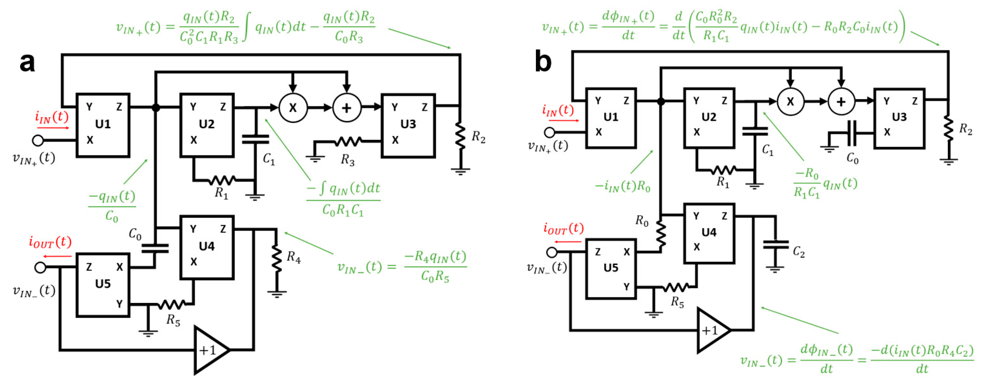
| Zhao et al. [63] | Memcap. | No | Floating | Charge | Current Conveyor Multiplier Adder | Yes |
| Memind. | Current |
Publisher’s Note: MDPI stays neutral with regard to jurisdictional claims in published maps and institutional affiliations. |
© 2021 by the authors. Licensee MDPI, Basel, Switzerland. This article is an open access article distributed under the terms and conditions of the Creative Commons Attribution (CC BY) license (https://creativecommons.org/licenses/by/4.0/).
Share and Cite
Romero, F.J.; Ohata, A.; Toral-Lopez, A.; Godoy, A.; Morales, D.P.; Rodriguez, N. Memcapacitor and Meminductor Circuit Emulators: A Review. Electronics 2021, 10, 1225. https://doi.org/10.3390/electronics10111225
Romero FJ, Ohata A, Toral-Lopez A, Godoy A, Morales DP, Rodriguez N. Memcapacitor and Meminductor Circuit Emulators: A Review. Electronics. 2021; 10(11):1225. https://doi.org/10.3390/electronics10111225
Chicago/Turabian StyleRomero, Francisco J., Akiko Ohata, Alejandro Toral-Lopez, Andres Godoy, Diego P. Morales, and Noel Rodriguez. 2021. "Memcapacitor and Meminductor Circuit Emulators: A Review" Electronics 10, no. 11: 1225. https://doi.org/10.3390/electronics10111225
APA StyleRomero, F. J., Ohata, A., Toral-Lopez, A., Godoy, A., Morales, D. P., & Rodriguez, N. (2021). Memcapacitor and Meminductor Circuit Emulators: A Review. Electronics, 10(11), 1225. https://doi.org/10.3390/electronics10111225