1. Introduction
In recent years much progress has been made in microgrids (AC, DC, and hybrid AC/DC) as they allow easier integration of both renewable energy resources and energy storage systems in the electrical power grids [
1,
2,
3,
4].
Microgrids are local grids formed by distributed generation (DG) such as renewable energies (wind and photovoltaic (PV) energy), non-renewable energies (diesel and fuel generators), electric energy storage (EES), and loads [
5,
6,
7]. A typical structure of an AC microgrid [
4,
5] is depicted in
Figure 1 [
6,
8,
9].
Most DGs are interfaced to microgrids through switching converters (AC/DC, DC/DC, or DC/AC) and must have the capability to operate in either one of two modes: connected to AC large scale grid (
Figure 1 switch ON) or in the islanded mode (
Figure 1 switch OFF), when the microgrid is operated separated from the grid [
4,
5,
6,
8,
10,
11,
12].
DG systems have advantages over conventional generators due to the high level of controllability and operability (increasing the stability in the electrical systems). One important advantage of microgrids is the improvement of supply reliability for consumers, although there are some difficulties in the standardized equipment [
5,
13,
14].
There is already some regulation for the interconnection of DGs to the grid and in case of failure the disconnection from the grid is required. However most DGs are not ready to be directly connected to AC grids, needing power electronic converters to enable their integration [
3,
5,
15].
Modern electronic loads are DC operated and PV panels generate DC power, therefore for efficiency it is advisable to connect electronic loads and PV panels directly to a DC bus (DC microgrid), through DC-to-DC converters (AC/DC conversion is no longer necessary). The coordination of these DC microgrids is easier in comparison with AC microgrids requiring simpler management algorithms. One big advantage of DC microgrids regarding AC microgrids is the absence of reactive power and harmonics, thus increasing the electric power quality. Another advantage of DC microgrids over AC microgrids is the reduction of conversion losses of inverters between the DC sources and loads. A typical structure of a DC microgrid is represented in
Figure 2 [
1,
16,
17,
18,
19,
20].
The recently emerged hybrid AC/DC microgrid combines the advantages of both DC and AC systems. Hybrid microgrids have been proposed to replace existing ones (AC or DC) in order to reduce multiple AC–DC–AC or DC–AC–DC conversions to individual AC or DC microgrids. Additionally, in this topology there are two possible operation modes: microgrid connected to the grid and microgrid in islanded mode. This new topology (hybrid AC/DC microgrid) can simplify the integration process of DC power technologies into existing AC systems and vice-versa.
Figure 3 shows a typical structure of a hybrid AC/DC microgrid [
4,
13,
14,
21,
22,
23,
24].
Multilevel converters enable high power and voltage processing using relatively low hold-off voltage semiconductors. In hybrid microgrids the power control should be bidirectional and harmonic distortion must show low values [
25,
26,
27,
28,
29]. Among the most common multilevel converter are the neutral point clamped (NPC) converter [
30], the flying-capacitors converter [
31], and the cascaded multicell with separate DC sources [
32]. The predictive control method has been used to control multilevel converters and sinusoidal pulse width modulation (PWM), sliding mode, and space-vector modulation (SVM) [
33,
34,
35,
36,
37].
A control method that improves the droop control for DC microgrids is described in [
1]. It takes into account the line resistance in the droop control and dc-bus voltage deviation increases with increasing load power, using a distributed control. However, this control method assumes the power converter as a linear system, neglecting also the converter dynamics. Therefore, in this work, the microgrid DC voltage control is developed considering the NPC converter non-linear dynamic model. A modified backstepping control technique is hereafter proposed to deal with the non-linear dynamics of the NPC converter while controlling the microgrid DC voltage.
A flexible control system for distributed generation with hybrid adaptive voltage and current control is presented in [
7]. The control of active power is done using proportional-integral (PI) compensation, even when there is frequency variation. However, despite the enhanced power quality system, it uses an LCL filter and it is only single-phase. We propose the use of NPC converters and robust BP control to improve the power quality, obtaining very low total harmonic distortion (THD) using only an L filter. The controller is designed for three-phase systems usually found in AC connected microgrids.
Lyapunov based backstepping control allows the design of robust and stable controllers. Virtual or intermediate reference quantities are used as intermediate control variables. Backstepping controllers can establish a relationship between the models of converters and control functions, ensuring the control system stability and robustness [
38,
39,
40,
41,
42,
43,
44].
The backstepping control is used in [
39,
42] for a distributed hybrid photovoltaic panel that uses the DC–DC buck–boost converter linked to a single-phase inverter. In [
39] the results show that this control method regulates the DC link of the DC–DC converter to obtain the maximum power point of the photovoltaic panel, and the AC current of the inverter contains low harmonic distortion. However, the control of the AC current of the single-phase inverter is done assuming separation of the DC link voltage dynamics to avoid distortion in the AC current due the DC load disturbances. Additionally, in the DC–DC buck–boost converter the control law is obtained by integration of the derivative of the duty cycle modulation function. The approach applied to 3-phase NPC converter results in very high gains and consequently the control laws are sensitive to AC voltage distortion. Therefore, to avoid sensitivity to AC voltage distortion while easing the control law, a novel backstepping approach is hereafter presented, which in addition reduces digital signal processing time. It allows the NPC converter, interconnecting a hybrid microgrid, to control the DC voltage and AC currents with high power quality, without assuming dynamic separation.
Predictive control applied to power converters is a simplification of optimal control theory valid given the converter discrete nature and finite number of switching states. Predictive controllers for power converters follow the subsequent design steps [
37]: (a) the power converter dynamic model is obtained, identifying the switching states and their relationship to voltages or currents; (b) a cost function is defined to represent the desired behavior of the system; (c) the dynamic model is discretized to predict which is the best switching state to optimize the cost function. This approach needs to predict output currents resulting from the application of all the NPC 27 vectors.
The new backstepping predictive control method here proposed, applied to the NPC converters in hybrid microgrids, innovates in the predictive control design in steps (a) where the model is used to compute the NPC control vectors, using a Lyapunov candidate function to ensure stability; (b) the cost functional is defined with the weighted errors of the control vectors regarding the applied vectors; (c) the NPC optimal switching state is obtained by minimizing the norm of the distance between the needed control vector and the NPC converter available vectors. This new approach was not reported previously in the backstepping or in predictive literature [
37,
42] and avoids predicting the converter outputs for all the 27 vectors.
When the DC microgrid is in the voltage control mode, the backstepping method is applied to the error of the squares of DC voltage and its reference value to obtain the virtual AC current. When the AC microgrid is in the power control mode, the power of the AC microgrid is set and the DC microgrid operates as the source microgrid.
The obtained control laws define the NPC output vector required to control the NPC AC currents and to balance its capacitor voltages. Since the available NPC vectors are only 27, the minimization of a cost function (like in the predictive approach) is used to find the NPC available vector closer to the required. This technique is termed backstepping predictive (BP).
Simulation and experimental results show that the BP controlled NPC converter is capable of regulating the DC microgrid voltage at the interconnection point by adjusting the power conversion of the AC microgrid to compensate for the variations of the DC microgrid voltage, which depend on the variations of the DC loads and distributed power sources. The NPC capacitors voltage balancing with the BP method is much faster than the PWM backstepping method with carrier offset. AC currents show lower harmonic distortion and the power factor is almost unitary. In the AC microgrid power control mode, the fast power step response shows that the converter is useful to regulate the microgrid AC frequency, primary power control, or to adjust the power level in secondary power control. These capabilities can be advantageously used to further strengthen smart grid operation.
The BP control method of the hybrid microgrid applied to the NPC converter is stable, robust, and with fast response in AC power conversion to deal with variations of the DC microgrid voltage, to balance the capacitor voltages or to adjust the power/frequency level of the AC microgrid.
2. Hybrid Microgrid Models and Controller Design
This section designs the modified backstepping method for the NPC converter interconnecting a hybrid microgrid. Control is applied to DC microgrid voltage or to AC microgrid power/frequency. The power factor is controlled to be near unity.
Figure 4 shows the circuit of the NPC converter that interconnects the DC microgrid section to the AC microgrid. The voltage
Udc is the DC microgrid voltage,
idc is the current flowing from the DC microgrid, through the NPC, and currents
i1,
i2, and
i3 are the three phase AC currents of the AC microgrid, which flow into the three AC phases with voltages
UL1,
UL2, and
UL3, using coupling coils, with self-induction coefficient,
L, and loss resistance,
R. The NPC converter two capacitors,
C1 and
C2, have voltages
UC1 and
UC2, which should be approximately balanced to
Udc/2. The legs of the NPC converter can have three states, characterized by the variable
γk:
where
k, ∈ {1, 2, 3}, and
Sk3 = 1 −
Sk1 and
Sk4 = 1 −
Sk2.
2.1. Model of NPC Converter in Hybrid Microgrids
The time
t dynamic equations of currents
id and
iq, in
dq, are obtained by applying Kirchhoff laws to
Figure 4, and the Clark-Concordia and Park transforms to AC currents and voltages [
27]:
The id and iq currents are the AC NPC currents, i1, i2, and i3, in their direct and quadrature components, respectively, ω is the angular frequency of the AC microgrid, γd, γq, and γ0 represent the semiconductors on-off state, γ1, γ2, and γ3 in dq coordinates and ULd and ULq are the direct and quadrature voltages of the AC microgrid. It is observed that the dynamics of currents id and iq are non-linear, but can be controlled by γd and γq, respectively.
The equation that describes the dynamic evolution of DC voltage, in
dq coordinates, is given by [
27]:
This equation indicates that the dynamics of the DC voltage can be enforced using the current id, while the quadrature current iq and DC current idc can be considered as disturbances. In the DC voltage dynamics equation, it is supposed C1 = C2 = C. In the NPC converter, the id current is considered the virtual control input (AC current) to control the DC voltage, when control is applied to the voltage at the interconnection point of the DC microgrid.
In the DC terminals of the NPC converter, the dynamic behavior of the capacitor voltage unbalance error,
eUC =
UC1 −
UC2, is given by [
27]:
2.2. Design of DC Backstepping Virtual Control Input
To control the DC microgrid voltage, using the backstepping method, the error between the squares of the DC voltage reference and the DC voltage,
eUdc2, is defined as
where
UdcRef is the reference DC voltage of the DC microgrid. Let the Lyapunov function,
V1, positive definite, be [
44]:
To ensure stability, the
V1 time derivative must be negative definite [
44]:
where
KeUdc2 is a positive constant. Substituting in (8) the error between the DC voltage squares,
eUdc2 (6), the squared DC voltage dynamics equation, (4), and after some manipulation, the reference value for the virtual control current,
idRefDC, is obtained:
Equation (9) can be simplified. Considering a unit power factor, the quadrature AC current component is nearly zero (
iq ≈ 0). The direct component of the switch state variable,
γd, which corresponds to the duty factor (
γd ≠ 0), is approximately equal to
γd ≈ 2
ULd/
Udc, obtained from (2) at steady state and neglecting losses. Therefore, the reference current,
idRefDC, is given under the above conditions by
In DC microgrids for the voltage control mode the reference virtual direct current is
idRef =
idRefDC. To control the
id current, the
id current error,
eid, is defined by
where
idRef is the reference current, or virtual current, obtained in (10). Using a composite positive definite Lyapunov function,
V2:
which is the sum the quadratic errors of the voltage
Udc squared and the current
id. The
V2 time derivative must be negative to ensure stability:
where
KeUdc2 was defined in (8) and
Keid is a positive constant. Substituting in (13)
eUdc2 and
eid by (6) and (11), respectively, using the dynamic behavior equation of current
id, (2), and squaring the
Udc voltage, (4), after algebraic manipulation, the reference component,
γdRef, to control the converter
γd is obtained,
Defining the error of the quadrature current component,
iq,
where
iqRef is the reference
iq current, which should be zero if a unit power factor is required (
iqRef = 0). Choose again a positive definite Lyapunov function,
V3 (16), and compute its time derivative (17):
Assuming
Keiq > 0 guarantees the control stability criterion. Substituting in (17) the current error
iq,
eiq, and using (3), which defines the dynamic behavior of the current
iq, it is received the reference component,
γqRef, of the quadrature control of the converter legs state
γq,
To balance the error of capacitor voltages, the positive Lyapunov function
V4 is chosen and defined by:
Computing the time derivative of
V4,
dV4/
dt, and making it negative gives:
where
KeUC is a positive constant. Substituting in (20) the equation of the dynamic model of the capacitor voltage unbalance error gives the control law with the reference current,
IeUCRef, to balance capacitor voltages,
The current for balancing capacitor voltages is given by the product of the squares of the switch legs control variables,
γd and
γq, with the currents,
id and
iq, respectively,
2.3. Design of DC Backstepping Predictive (BP) Controller
The NPC converter,
Figure 4, according to (1), has 27 possible combinations of the converter switch legs states. A cost functional is defined with the weighted errors, for normalization, of the converter switch state legs variables,
eγd and
eγq, and the current that allows the capacitor voltages to be balanced,
eIeUC, are given by:
The error weights
ργd and
ργq of the converter switch leg states, and
ρIeUC for the current to balance the capacitor voltages, allow normalizing the errors while adjusting the control action of the quantities to be controlled. The cost functional
CFPredictive is given by
Predictive control algorithm applies all 27 combinations of converter switch leg states to calculate the cost functional, CFPredictive, and choose the combination that minimizes the cost functional for controlling DC microgrid voltage and AC currents and to balance the capacitor voltages, using the BP equations, ensuring control stability.
The drive of the NPC converter semiconductors can also be done using PWM modulation instead of the predictive control, with the cost functional, using the same backstepping control equations. With PWM modulation the capacitor voltage balance can be achieved by introducing and feedback regulating a carrier waveform offset. The PWM modulation further reduces the computational cost, suitable for low cost processors, but the results will show that the convergence speed of the capacitor voltage balance is slower than with the BP control.
2.4. AC Microgrid BP Controller Design
In AC microgrid power/frequency control mode the active power reference,
PRefAC, is defined and from the AC microgrid power equation,
PAC,
the reference current (28) of the AC microgrid,
idRefAC, is calculated, assuming a rotating reference frame where the quadrature voltage is null,
ULq = 0.
The NPC converter interconnecting a hybrid microgrid can operate in DC voltage control mode,
Mode = 1 (
Section 2.2), or AC microgrid active power control mode,
Mode = 0, described in this
Section 2.4. The direct current reference,
idRef, is defined as a function of the control mode by:
The design of the AC microgrid BP controller is similar to those of the DC microgrid. However, in this control mode the DC voltage,
Udc, is the DC microgrid voltage. Defining a positive Lyapunov function,
V2AC, in (30) to control the
id current, its time derivative is (31).
Assuming
Keid > 0 ensures the control stability criterion. Substituting in (31) the error of
id current,
eid, and using (2), which defines the dynamic behavior of current
id, gives the reference component,
γdPRef, of the direct control quantity,
The difference in AC microgrid control mode from DC microgrid control mode is in the direct current reference setting, idRef. In the DC microgrid the control law is (14) to control the DC voltage, Udc. In the AC microgrid the value is calculated as a function of the active power, which allows one to adjust the power/frequency of the AC microgrid. In the AC microgrid the control law of the direct variable to control the converter legs (32) does not have the error between the DC voltage squares, eUdc2 as in (14).
The same cost functional (26) is used to control the hybrid microgrid NPC converter in the AC power mode (Mode = 0).
2.5. Block Diagram of DC/AC BP Controller
The design of the DC microgrid BP controller must ensure regulation of the DC voltage, control the AC input currents so that the power factor is almost unity and the voltages of the capacitors are balanced. The AC microgrid BP controller regulates AC power, supporting the frequency control and voltage of the AC microgrid. The hybrid microgrid AC/DC BP control was designed using the explained BP methodology.
Figure 5 shows the block diagram with the BP controller for NPCs interconnecting hybrid microgrids.
In the control block diagram for the hybrid microgrid the converter voltage of the DC microgrid is sampled and compared to the reference. Applying the backstepping method to the voltage dynamics Equation (4) results in the voltage controller, which calculates the virtual current value, idrefDC.
From the reference AC power, PRefAC, the virtual current value, idrefAC, is calculated. In the DC microgrid control mode (Mode = 1), which regulates the DC voltage, idref = idrefDC. In the power/frequency control mode of the AC microgrid (Mode = 0) it is idref = idrefAC. AC currents are sampled and the Park transform applied. The obtained dq currents, id and iq, are compared to the virtual quantities, idRef and iqRef = 0. The application of the BP control method results in defining the legs control variables, γdRef and γqRef. The BP method is also applied to the capacitor voltage error to obtain the IeUCRef current needed to balance the capacitors voltage. The predictive controller analyses all combinations of semiconductor states to minimize the cost of a functional based on the weighted errors of the available control actions.
3. Simulation and Experimental Results of the Hybrid Microgrid
This section presents the simulation and experimental results of the hybrid microgrid. The simulations in MATLAB/Simulink were based on the hybrid microgrid model and on the controller obtained by the BP method. Experimental results were obtained from a laboratory prototype of the NPC converter,
Figure 4, which was implemented to experimentally test the performance of the hybrid microgrid.
Simulation and experimental results are presented in the steady state, for the DC and AC microgrid, and in transient operation. Simulation and experimental results of the BP controller are compared.
Table 1 lists the parameters and values used in the simulation and experimental verification.
3.1. DC Microgrid Results
This section shows the results of the operation of the hybrid microgrid with the converter controlling the voltage of the DC microgrid.
Figure 6 shows the simulation results of the DC voltage and AC currents of the microgrid using the BP control method.
Simulation results show that in the steady state the BP DC voltage controller regulates the DC microgrid voltage. AC currents are sinusoidal, with low harmonic distortion, 1.7%. In the laboratory prototype the results of the DC voltage control and the AC currents control present the same behavior as the simulation results of
Figure 6.
Simulation results of capacitor voltages are shown in
Figure 7. These results show that from a 10% voltage imbalance the BP controller takes approximately 0.05 s to balance the capacitor voltage (
Figure 7a). Compared to PWM modulation, whose capacitor voltage balance is obtained by adjusting the carrier offset in a process that takes approximately 1.6 s (
Figure 7b), it is concluded this time is too long to enable the use of NPC converters with PWM modulation and carrier offset control in a bipolar microgrid.
The experimental and simulation results of
Figure 8 show the response of the predictive control NPC converter contributing to the regulation of the DC voltage at the interconnection point when there is a power step variation on the load or on the distributed renewable energy sources in the DC microgrid.
Figure 8a,c shows the case where there is a 100% increase in the load power. The BP controller adjusts the reference current of the AC microgrid,
idRefDC (10), to compensate for the voltage droop
Udc. In
Figure 8b,d there is a 50% reduction on the load power, causing a reduction of the DC microgrid voltage droop. The results of
Figure 8 show that the static error of the
Udc voltage is lower than 0.5%. In
Figure 8a,c, during the transient, there is a reduction in DC voltage of approximately 1%. In
Figure 8b,d there is an increase of about 1%, during the transient. After the transient, the DC voltage follows the reference with the above stated static error. The result also shows that the AC microgrid currents are almost sinusoidal (1.8% and 1.7% total harmonic distortion for experimental and simulation results, respectively) and with a fast response to load changes in the DC microgrid. The current step response time is in the order of the ms, limited by filtering inductors and available voltages and not by the controller.
Both the simulation and experimental results show that the BP controller applied to the hybrid microgrid NPC converter in the DC microgrid voltage control mode, Mode = 1, control the DC voltage, balance the capacitors voltages and AC currents, in the steady state and transient operation.
3.2. AC Microgrid Results
This section shows the results of the operation of the hybrid microgrid in the AC power/frequency control mode,
Mode = 0. In this mode of operation, the grid operator (secondary control) can set the active power, or reference AC current, to help adjusting the power or the frequency of the AC microgrid.
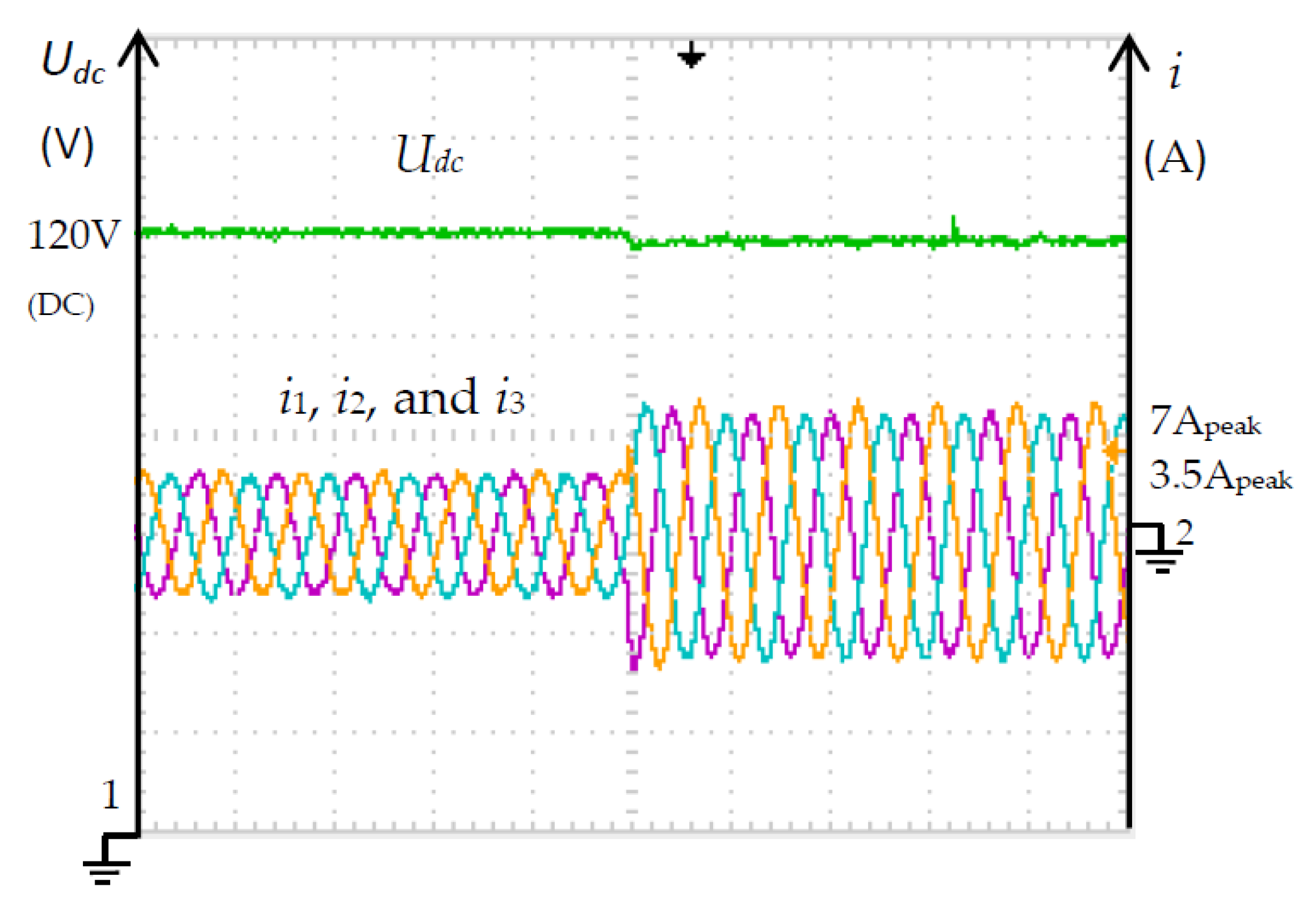
Figure 9 shows the experimental results for a stepwise increase of the AC power injected into the AC grid to twice the previous value. The AC currents were almost sinusoidal (THD = 1.8%), balanced, with step response almost instantaneous, regarding the AC period, allowing the NPC converter to be used as a primary AC microgrid contributor for frequency regulation.
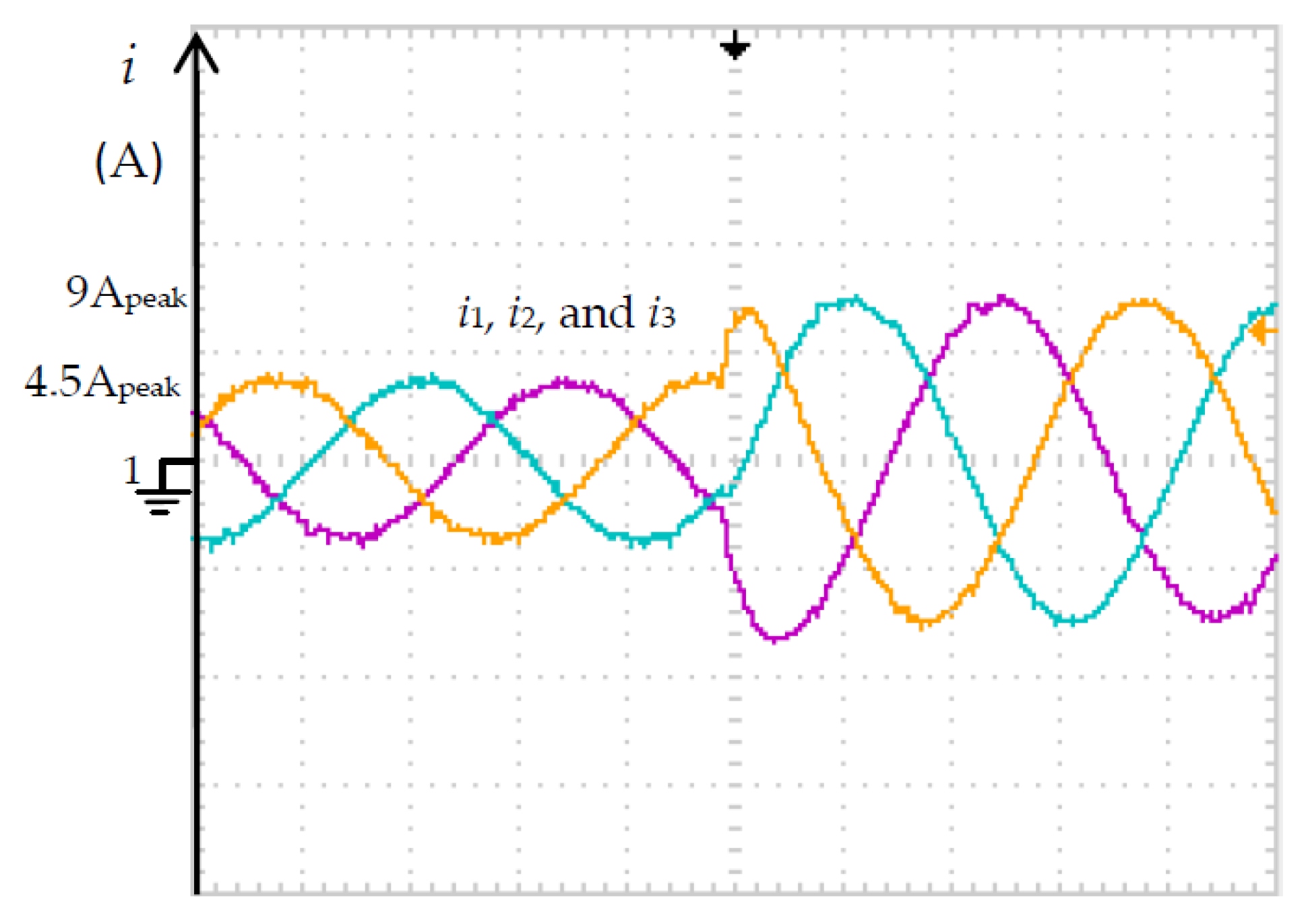
Figure 10 shows the experimental results of AC current and voltage,
i1 and
UL1, in this case to a stepwise increase of the reference AC power injected into the DC grid. The AC current increased from 4.5 A
peak to 9 A
peak.
Experimental results (
Figure 11a) of microgrid NPC converter in voltage mode control at the steady-state show low distortion almost sinusoidal AC currents with THD of 1.8% (
Figure 11b).
Figure 12 shows an experimental transient of the DC voltage regulation using an integral proportional controller (PI), tuned using a damping factor of 0.7, and PWM modulation when there is a 100% increase in the DC load power. The results show that the PI adjusts the AC current, with a slower response time than the BP controller, causing a reduction of the DC voltage, during the transient, of approximately 3%, and an increase in the steady state error. Besides, the AC currents show some unbalance, which causes higher DC voltage ripple.
Experimental results were obtained using the NPC prototype depicted in
Figure 13, using digital scope 100 MS/s Tektronix TDS 2014, and class A power quality analyzer Fluke 435.
Simulation and experimental results show that the BP controller is capable of properly controlling the NPC converter to interconnect a hybrid microgrid. In the DC microgrid voltage control mode, proper conversion power adjustment between the AC microgrid and DC microgrid is observed to compensate for DC voltage variations caused by DC load changes or renewable generation at the converter point of interconnection. Using the BP controller allows to improve the capacitors voltage balance convergence time compared to PWM backstepping controller. The fast response of the AC current variation allows this converter to be used in the AC power control mode for both secondary AC power control and mainly primary AC frequency control. AC currents are sinusoidal, with low harmonic distortion, and the power factor is unitary.
The power factor can be made nearly unity, while the AC current (in periodic regime) is less distorted (THDi ≈ 1.8%) than the AC voltage UL1 (THDU ≈ 2.5%). Regarding simulations and theoretical results, experimental deviations for the THDs are around 5%, while deviations for the AC currents are around 8.8%, as the theoretical model assumes a unity efficiency converter.
4. Conclusions
This paper presented a new control method, BP, for controlling hybrid microgrids interconnected with NPC converters. The converter, like three-phase two-level converters, can operate in the DC microgrids primary control mode using the AC microgrid as a source, or in the AC microgrid control mode as the DC microgrid as a source.
From the modelling of the NPC converter circuit that interconnects two hybrid microgrids, DC and AC, the equations of the state space variables in dq are presented. In the DC microgrid control mode, the BP controller was designed to control the DC grid voltage, balance the converter capacitors voltage, and control AC currents to have near unity power factor or control reactive power. In the AC microgrid control mode the relationship between AC power and AC currents are BP controlled to enforce the required active and reactive powers.
The MATLAB/Simulink simulation results and laboratory prototype experiments show that in the DC microgrid control mode the microgrid DC voltage at the converter interconnection point is regulated, the AC currents are almost sinusoidal (distortion around 1.7%), the power factor is mostly unity and the BP controller presents fast response to the load or renewable power variations of the DC microgrid, converting more or less power from the AC microgrid, to compensate the DC load or renewable generation, contributing to the regulation of the DC microgrid voltage. The results show that the capacitor voltage balance is well matched and from a voltage imbalance it is found that the BP controller is much faster to balance the capacitor voltage compared to the carrier offset PWM method.
The tests carried out on the NPC converter, which interconnects two hybrid microgrids, can operate in the AC microgrid control mode. In this mode the AC microgrid operator sets the power level, which has fast step response, allowing the primary frequency or secondary power control to be assisted.
The BP approach can be further exploited in bipolar microgrids applications, where it can be used to balance the positive and negative voltages, in spite of positive/negative strong load mismatches or asymmetrical bipolar voltages. BP can also be used for a first preview of secondary control in microgrids.


