Article

High-Frequency and High-Voltage Asymmetric Bipolar Pulse Generator for Electroporation Based Technologies and Therapies

1
Faculty of Electrical Engineering, University of Ljubljana, Tržaška 25, 1000 Ljubljana, Slovenia
2
Department of Experimental Oncology, Institute of Oncology Ljubljana, Zaloška 2, 1000 Ljubljana, Slovenia
3
Faculty of Health Sciences, University of Ljubljana, Zdravstvena Pot 5, 1000 Ljubljana, Slovenia
*
Author to whom correspondence should be addressed.
Electronics 2021, 10(10), 1203; https://doi.org/10.3390/electronics10101203
Submission received: 17 April 2021 / Revised: 10 May 2021 / Accepted: 13 May 2021 / Published: 18 May 2021
(This article belongs to the Section Bioelectronics)

Abstract

:
Currently, in high-frequency electroporation, much progress has been made but limited to research groups with custom-made laboratory prototype electroporators. According to the review of electroporators and economic evaluations, there is still an area of pulse parameters that needs to be investigated. The development of an asymmetric bipolar pulse generator with a maximum voltage of 4 kV and minimum duration time of a few hundred nanoseconds, would enable in vivo evaluation of biological effects of high-frequency electroporation pulses. Herein, from a series of most commonly used drivers and optical isolations in high-voltage pulse generators the one with optimal characteristics was used. In addition, the circuit topology of the developed device is described in detail. The developed device is able to generate 4 kV pulses, with theoretical 131 A maximal current and 200 ns minimal pulse duration, the maximal pulse repetition rate is 2 MHz and the burst maximal repetition rate is 1 MHz. The device was tested in vivo. The effectiveness of electrochemotherapy of high-frequency electroporation pulses is compared to “classical” electrochemotherapy pulses. In vivo electrochemotherapy with high-frequency electroporation pulses was at least as effective as with “classical” well-established electric pulses, resulting in 86% and 50% complete responses, respectively. In contrast to previous reports, however, muscle contractions were comparable between the two protocols.

1. Introduction

In electroporation due to the exposure of cells to high-voltage electric pulse, the cell membrane becomes permeable to molecules that otherwise cannot cross the cell membrane [1]. In reversible electroporation the cell recovers after the electric pulse application. In contrast, in irreversible electroporation (IRE) the cell dies due to excessive damage [2]. Electroporation is already well established in medicine and food processing [3,4]. The technology holds promises also in other fields, such as biomass production [5] and biotechnology [6]. However, different pulses are used in different electroporation-based applications i.e., pulse amplitude, pulse width, a number of pulses or bursts, and pulse or burst repetition rate [7,8,9]. In most applications, optimization of parameters still needs to be performed. Therefore, specific pulse generators, i.e., electroporators have to be designed for specific applications [10,11]. Additionally, electrical properties of biological loads vary considerably and due to electroporation their conductivity changes during the pulse application [12,13,14,15,16,17].
Electroporation is well established in cancer treatment, i.e., electrochemotherapy (ECT) and IRE. ECT is a local antitumor therapy, in which electroporation facilitates chemotherapeutic drug entry into cells [18,19]. According to the standard operating procedure, intratumoral or intravenous delivery of the chemotherapeutic drug bleomycin (BLM) or cisplatin (CDDP) is followed, by the application of eight high-voltage pulses, which are monopolar, 100 μs long, with a pulse repetition rate 1 Hz or 5 kHz and voltage to distance ratio between 1000 or 1300 V/cm (depending on the electrode type) [20,21,22]. IRE is clinically used as non-thermal ablation of normal and tumor tissue, in which cells die due to excessive damage during membrane permeabilization [23,24,25,26]. However, IRE does not cause the denaturation of proteins, scarring, and damage of blood vessels. Therefore, it has the potential to treat tumors near large blood vessels. In addition, the activation of the immune system was observed as in ECT [27,28,29]. However, an increase in temperature around the electrodes can be significant at higher amplitudes and a high number of pulses delivered to a limited volume of tissue [30]. Furthermore, nerve stimulation, muscle contractions, and pain are associated with high-voltage pulse delivery [19,25,31]. These are also observed in ECT and require additional patient management in terms of muscle relaxant administration prior to treatment [32,33]. Synchronisation of pulse delivery with ECG, is required when treatment is performed close to the heart, which renders the treatment procedure more complex [32,34]. Recently, it was suggested that by applying high-frequency bursts of bipolar pulses, named H-FIRE (High-Frequency IRreversible Electroporation), muscle contractions can be reduced without compromising the non-thermal mechanism of cell death [35,36]. They also suggest that electric field distribution in tissue is more homogeneous [35]. It was shown in vitro that the transmembrane transfer of molecules may be achieved with the same type of pulses [37]. However, H-FIRE pulses require higher amplitudes for cell disruption in comparison to longer monopolar pulses [37].
Recently, we demonstrated in vitro that high-frequency electroporation (HF-EP) can be used for ECT and that higher pulsed electric field, i.e., equal to 3 kV/cm in HF-EP than in “classical” ECT has to be used in order to obtain comparable effectiveness [38].
With the potential advantages of IRE over current ablation modalities, the technology seems uniquely suited also for cardiac ablation in the treatment of atrial fibrillation (AF) [24,39,40,41]. A term “Pulsed field ablation” (PFA) is defined as IRE that uses a burst of bipolar pulses of high-voltage and short duration to create a tissue injury without significant heating and injury to other tissues [42].
The electric field threshold for muscle contraction is two times lower than the threshold for electroporation (for 100 μs long pulses) [43]. The advantage of these specific high-frequency electroporation pulse characteristics might be in reducing muscle contraction and pain sensation during high-voltage pulse delivery [35,36,43]. Recently, a phenomena of electrical cell sensitization [44,45] and cancellation in the range of microsecond and sub-microsecond pulse duration were reported in vitro [46,47]. These effects i.e., sensitization, cancellation, nerve and muscle decreased excitation effects of the electroporation are still not well understood and further studies are needed, particularly in vivo, due to inconclusive results obtained in vitro [48,49]. Additionally, the use of asymmetric, HF-EP for HF-IRE that could enhance its effectiveness was suggested [50]. Therefore, the development of an asymmetric bipolar electroporator, with a variable setting of pulse duration and voltage amplitude for each half period of the pulse, that can be used in vivo enables a new insight and investigations of cancellation and sensitization relevance in vivo.
For generating electric pulses of up to several kV high-voltage amplitudes three different circuit concepts are used: generator with serial switches [51], Marx generator [52], and a modular pulse generator [53]. For the generation of asymmetric bipolar pulses, an asymmetric H-bridge generator is used where each half of the bridge is powered by its own power supply [54]. For the generation of high-voltage asymmetric bipolar pulses, a serial asymmetric H-bridge generator is, therefore, the simplest and economically most reasonable solution.
Until now, all H-FIRE studies used custom-made laboratory prototype electroporators based on an H-bridge. Therefore, the research is limited to a few research groups that have the knowledge and experience to design such custom devices. In addition, pulse delivery systems are most often only briefly mentioned and not described in detail in the literature.
In conclusion, according to the electroporators review, [10,55], published economic evaluations of ECT and IRE [56,57,58] and increase of interest in electroporation with bipolar pulses [38,59,60], there is still an area of pulse parameters that needs to be investigated. Here, we present the development of a serial asymmetric H-bridge generator that generates asymmetric bipolar pulses with a maximum voltage of 4 kV and a minimum duration time of a few hundred nanoseconds with the emphasis on the importance and the process of electronic component selection, and the concept and topology of developed electroporator. In addition, the in vivo evaluation of the developed device is presented, focusing on the first in vivo high-frequency electrochemotherapy (HF-ECT).

2. Methods and Materials

2.1. Prototype Device

A prototype device that generates high-frequency and high-voltage asymmetric bipolar pulses was developed from a prototype serial asymmetric H-bridge generator, digital delay generator DG645 (Stanford Research Systems, Sunnyvale, CA, USA), two high-voltage capacitor banks and two high-voltage power supplies HCP 350-6500 (FuG Elektronik GmbH, Schechen, Germany).

2.1.1. Serial Asymmetric H-Bridge Generator

The output stage of the developed device is a custom-made serial asymmetric H-bridge generator presented in Figure 1. The H-bridge is made of 4 S switches with the load in the middle of the H-bridge. Two resistors AZ151K (Ohmite, Warrenville, IL, USA) in series were used as a generator internal load to optimize the pulse fall time. The H-bridge is supplied from two galvanically separated DC links. Each DC link supplies the H-bridge diagonally, i.e., one DC link supplies the power for the positive pulse and the other DC link for the negative pulse on the load. Each DC link consists of five C 1 = 0.25 μF (B58031U9254M062, TDK, Tokyo, Japan) capacitors and five C 2 = 5 μF (B58033I9505M001, TDK, Tokyo, Japan) capacitors to achieve optimal frequency and capacitive response. Five R 2 = 10 M Ω (SM101031005F, Ohmite, Warrenville, IL, USA) resistors are used to evenly distribute the voltage across the capacitors. Two trigger inputs are used, the first to trigger the positive pulse and the second to trigger the negative pulse. Logical gates NOR (MC74AC02DG, ON Semiconductor, Phoenix, AZ, USA) are used at the inputs to prevent positive and negative triggering at the same time. The S switches are presented in more detail in Figure 2. Each S switch is developed from three SiC MOSFETs (C2M0045170D, Cree, Silicon Drive Durham, NC, USA) in series with 1700 V maximal drain to source voltage and 160 A maximal pulsed drain current. Resistors R 1 = 100 M Ω (SM102031006FE, Ohmite, Warrenville, IL, USA) are used to evenly distribute the voltage across the SiC MOSFETs during the off state. Driving circuit D.C. was designed from MOSFET driver IXDN609SI (IXYS, Beverly, MA, USA), isolated DC-DC converter MGJ2D052005SC (Murata Power Solutions, Westborough, MA, USA) and optical isolator ADuM210N0BRIZ (Analog Devices, Wilmington, MA, USA) [61]. More data on element selection, optimization of the driving and insulation circuit, testing MOSFETs in series, and fabrication of the device are presented in the Appendix A.

2.1.2. Triggering of the Pulses

Two outputs of the digital delay generator were set and used to trigger and to define the duration and number of the positive and negative pulses within the burst of pulses. The outputs of the digital delay generators were connected to inputs, i.e., Trigger+ and Trigger- of the serial asymmetric H-bridge generator (Figure 1). If necessary, a function generator (33220A, Agilent Technologies, Santa Clara, CA, USA) was used to trigger several bursts from the digital delay generator.

2.1.3. High-Voltage Capacitor Bank

To supply the energy to the H-bridge generator during the high-current or long-duration treatments a high-voltage capacitor bank was connected to each DC link. Each high-voltage capacitor bank was made from four capacitors 947D501K112BJMSN (Cornell Dubilier Electronics, Liberty, SC, USA) in series. Capacitor banks were charged by high-voltage power supplies HCP 350-6500.

2.1.4. Measurement of the Output Pulses

Output pulses from the prototype device were measured with oscilloscope HDO6104A-MS (Lecroy, Chestnut Ridge, NY, USA), high-voltage differential probe HVD3605 (Lecroy, Chestnut Ridge, NY, USA), and current probe CP031A (Lecroy, Chestnut Ridge, NY, USA). Before in vivo experiment was conducted, the prototype device was evaluated on 80 Ω resistive load made from two resistors in series, i.e., 33 Ω resistor (AZ330KE, Ohmite, Warrenville, IL, USA) and 47 Ω resistor (AZ470KE, Ohmite, Warrenville, IL, USA). This value was chosen as the in vivo resistance of the tissue between the needle electrodes is close to 80 Ω [62]. All the measurements were analyzed in Matlab R2018b (MathWorks, Natick, MA, USA). The rise/fall time was defined as the time required for a pulse to rise/fall from 10/90% to 90/10% of the maximal measured voltage. Pulse width is defined by Full-Width Half-Maximum (FWHM). The pulse amplitude was defined as an average value above the 95% of the maximal measured voltage. Additionally, an amplitude relative error was determined as a difference between the set voltage and pulse amplitude.

2.2. In Vivo Experiments

2.2.1. Animals

Animal experiments were conducted in accordance with the principles and procedures outlined in the guidelines for animal experiments of the EU directives and permission from the Administration of the Republic of Slovenia for food safety, veterinary and plant protection was obtained (permission No.: U34401-1/2015/43).
In vivo experiments were performed on Balb/c female mice (Figure 3), 8 weeks old (Envigo, Udine, Italy) that were maintained under pathogen-free conditions at constant room temperature and a 12-hour day/night light cycle. Food and water were provided ad libitum. One day prior to tumor induction, their right flanks were shaved. Approximately 7 days after the injection of 0.5 × 10 6 CT26 cells subcutaneously (American Type Culture Collection, Manassas, VA, USA) or when the tumors reached 40 mm 3 , mice were divided into nine experimental groups (6-7 animals), (i) without treatment (Control); (ii) chemotherapy with BLM; (iii) chemotherapy with CDDP; (iv) treatment with “classical” electroporation pulses (ECT pulses); (v) treatment with HF-EP pulses (HF-ECT pulses); (vi) ECT with BLM using “classical” electroporation pulses (BLM/ECT), (vii) ECT with CDDP using “classical” electroporation pulses (viii) ECT with BLM using HF-EP pulses (BLM/HF-ECT) (ix) ECT with CDDP using HF-EP pulses (See Table 1).

2.2.2. Treatment Protocol

Two ECT protocols with BLM or CDDP were compared in vivo: ECT with well-established “classical” ECT pulses (8 × 100 μs) and ECT with HF-ECT pulses. Treatment consisted of intratumoral injection of BLM (Bleomycin medac, Medac, Wedel, Germany; 5 μg; 40 μL) or CDDP (Cisplatin Kabi, 1 mg/mL, Fresenius Kabi AG, Bad Homburg, Germany; 40 μg; 40 μL), pulse delivery was followed 2 min later. For the application of electric pulses, parallel plate stainless-steel electrodes with 6 mm interelectrode distance were used. A water-based gel was used to ensure good conductivity at the point of contact between electrodes and the skin overlaying the tumors. Physiological solution (40 μL) was injected in the control group and groups with electric pulses only. Mice were anesthetized with inhalation of 2% (v/v) isoflurane in pure oxygen in the induction chamber. Afterward, the mouse muzzle was placed under an inhalation tube to keep mice anesthetized during the treatment.
In “classical” ECT electric pulses were delivered with a commercially available BetaTech electroporator (Electro cell B10, Leroy Biotech, Saint-Orens-de-Gameville, France). Electric pulse parameters: 780 V, 1.3 kV/cm voltage to distance ratio, eight 100 μs long pulses were applied in two perpendicular directions (4 + 4) at 1 Hz pulse repetition rate. In HF-ECT pulses were delivered by the newly developed prototype device. One combination of electric pulse parameters was used (2.5 times higher voltage over distance [38]): eight bursts of 50 bipolar square wave pulses 1 μs-1 μs-1 μs-1 μs (duration of a positive polarity-pause between pulse polarities-duration of a negative polarity-pause between bipolar pulses) at 1 Hz burst repetition rate resulting in equal total pulse amplitude time for both pulse protocols. Pulse voltage amplitude in HF-ECT was 1950 V (3.25 kV/cm voltage to distance ratio).
The therapeutic effect was estimated three times per week by measuring tumor volume using a vernier caliper. Tumor volume was calculated according to: V = a × b × c × π 6 , where a, b and c were three mutually orthogonal tumor diameters. Mice were euthanized when tumor volume reached 350 mm 3 . A Kaplan–Meier survival plot was constructed with the tumor volume of 300 mm 3 representing the endpoint event. Statistical test Survival LogRank was performed on survival results (SigmaPlot, Systat Software, San Jose, CA, USA).
In the scope of this study, we also evaluated muscle contractions during pulse delivery. A triple axis accelerometer BMA220 (DFRobot, Shanghai, China) was connected to Arduino UNO (Arduino, Boston, MA, USA). The accelerometer was taped with a micropore tape to the right hind foot during pulse delivery. Software captured and saved the measurements that were analyzed post festum in Matlab. The absolute acceleration was calculated and gravitation was not excluded.

3. Results

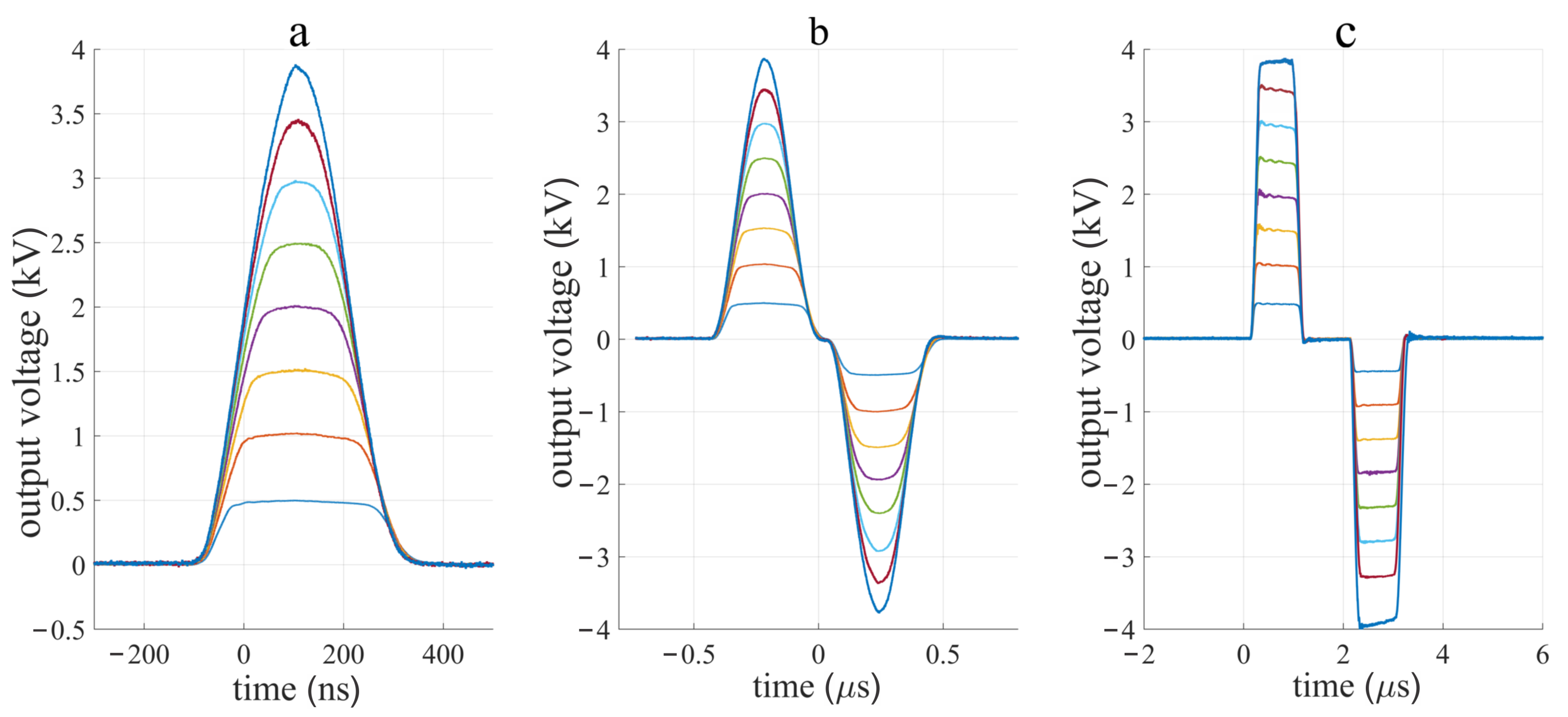
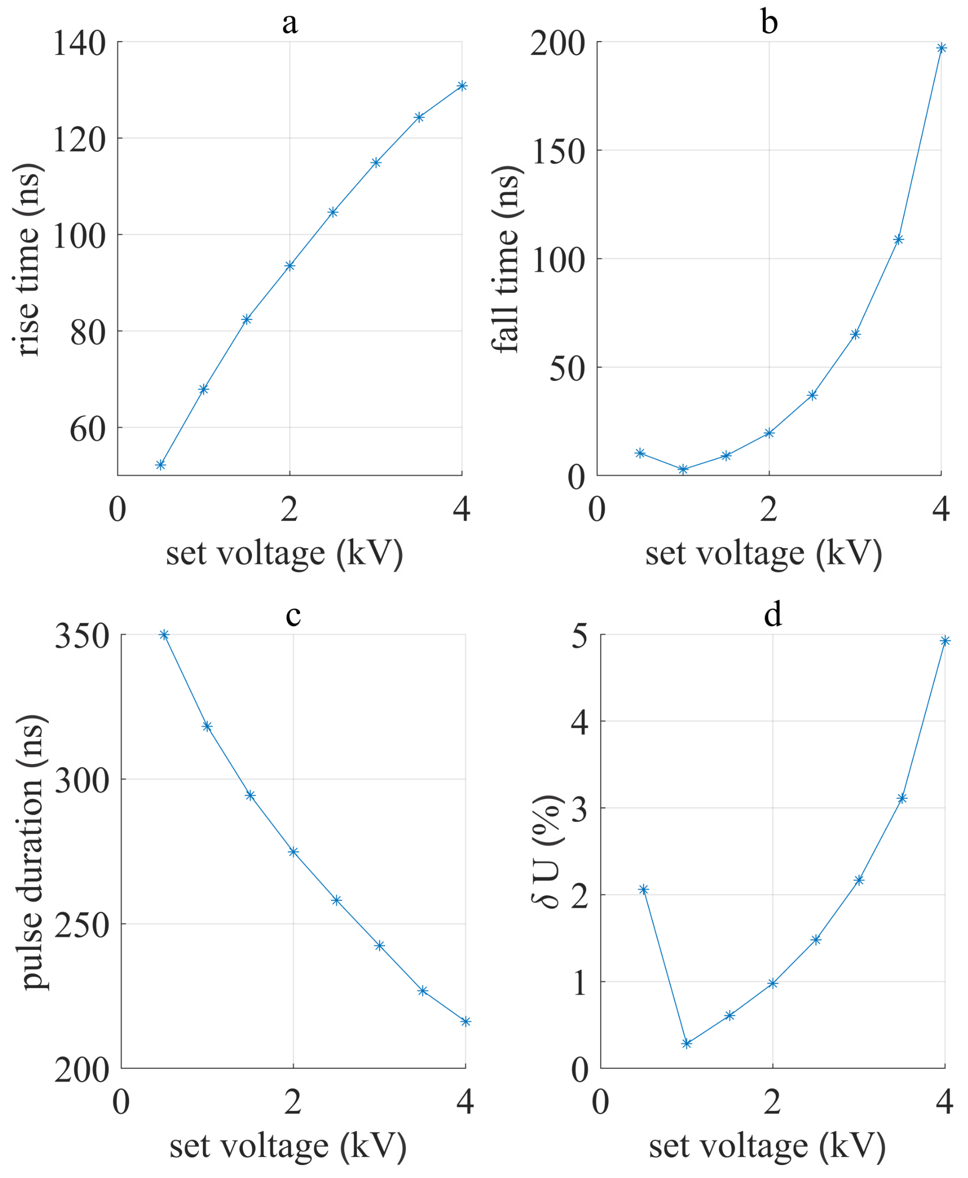
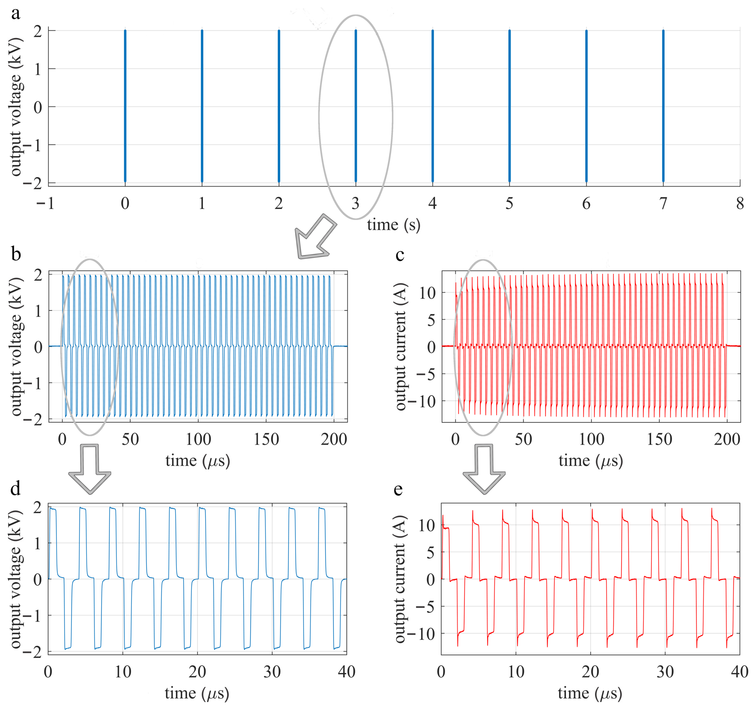
3.1. Device Performance

The measurement of monopolar and symmetric bipolar pulses with minimal pulse duration 200 ns and 1 μs are displayed in Figure 4. The capacitor charging voltage was set to 500 V and then raised to 4 kV in 500 V steps. Minimal duration pulses are limited by their rise and fall time and are therefore bell-shaped. In order to reach 4 kV the duration of the trigger pulse was increased to 260 ns that resulted in 200 ns FWHM pulse duration at 4 kV and longer pulses at a lower amplitude. At 1 μs FWHM pulse duration rise and fall times become negligible and the pulse shape square-wave (Figure 4c). The poles of the bipolar pulses are symmetric.
In Figure 5 symmetric and asymmetric pulse generation is presented. The pulse duration of a positive and negative polarity can be set independently from 200 ns (Figure 5a) to 1 ms. Similarly, pulse amplitude of negative and positive polarity can be set independently (Figure 5b,c). In Figure 5a the capacitor charging voltage was set to 4 kV and trigger pulse duration was set to 260, 400, and 800 ns for both polarities. With the two longer pulse durations, the pulse amplitude comes close to 4 kV and the pause between both polarities is reduced. In Figure 5b,c the amplitude of the first polarity was the same (4 kV) and trigger duration 260 ns (Figure 5b) or 1 μs (Figure 5c). Charging voltage of the second polarity (4 kV, 2 kV and 1 kV), and the trigger duration (260 ns, 400 ns, and 800 ns (Figure 5b) or 1 μs, 2 μs, 4 μs in Figure 5c) were changed. Figure 5 demonstrates that the minimum pulse duration and highest amplitude of the first polarity have good repeatability and can be followed by the pulse of opposite polarity of any pulse duration or amplitude within the operation range.
The monopolar pulse measurements from Figure 4 were further studied in detail. The rise and fall time, pulse duration, and relative error in amplitude δ U were calculated for each set voltage (Figure 6). As expected, both the rise and fall time of the pulse rises with set voltage. However, the maximal rise and fall time are below 150 ns that allows the generation of pulses with a minimum pulse duration of 200 ns at a maximal set voltage. At lower voltages, 200 ns pulse duration can be achieved by trigger pulse calibration. The maximal relative error in pulse amplitude is 5% which meets the desired performance.

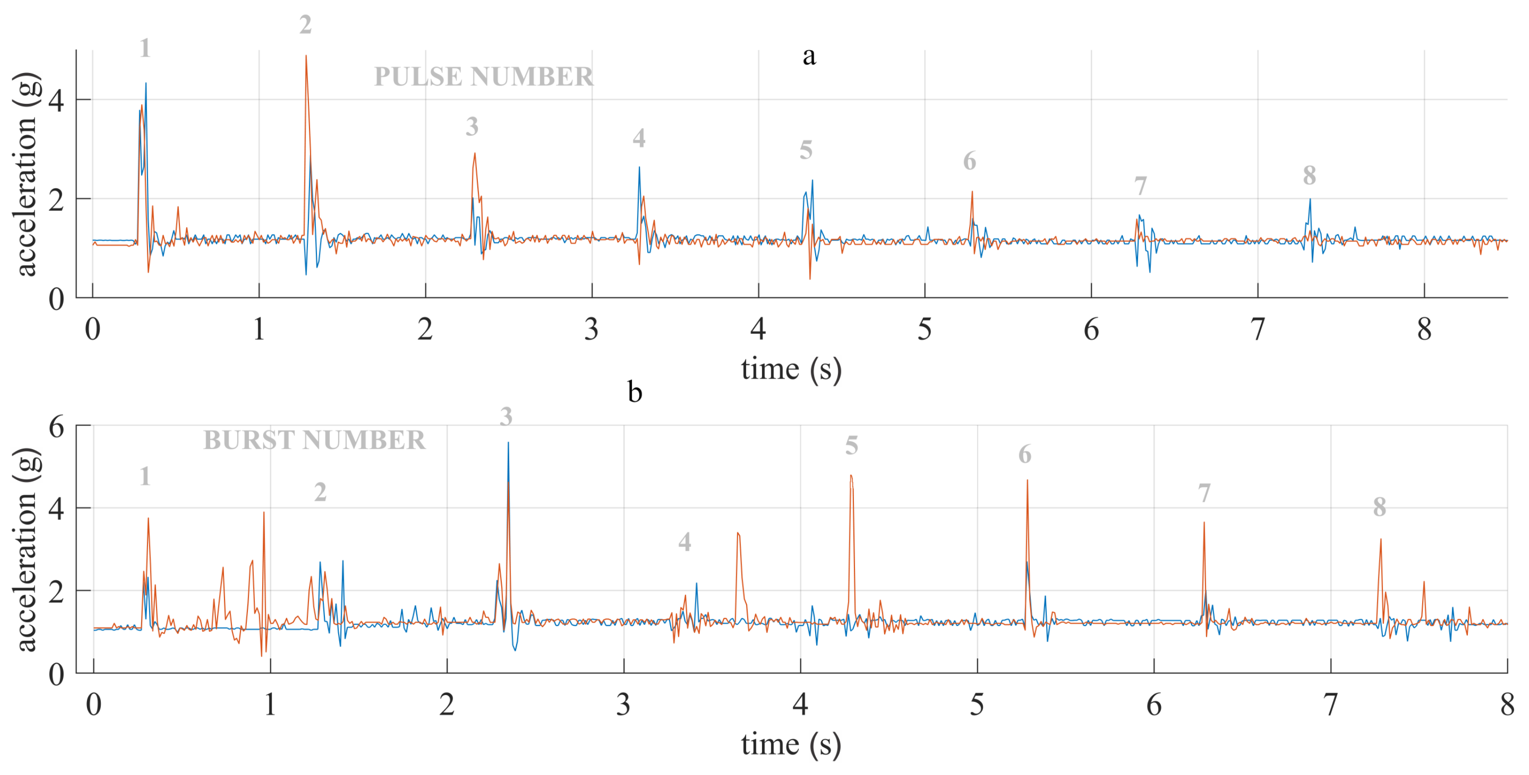
3.2. High-Frequency Electrochemptherapy In Vivo

The device was also tested “in vivo”. In Figure 7 current and voltage measurement of delivered HF-EP pulses are shown. Additionally, in Figure 8 the signals from the accelerometer attached to the mouse leg during the pulse delivery is presented. The accelerations in classical ECT pulses (eight monopolar, 100 μs long, 1 Hz pulse repetition rate, and pulse amplitude 780 V) are comparable to eight bursts of high-frequency 1-1-1-1 μs (duration of a positive polarity-pause between pulse polarities-duration of a negative polarity-pause between bipolar pulses) long bipolar pulses, burst repetition rate (1 Hz) as “classical” ECT pulse repetition rate, and higher voltage amplitude 1950 V. No significant difference in the muscle contractions were observed. Furthermore, the therapeutic effect of ECT with BLM in combination with HF-ECT pulses was investigated. Both, “classical” and HF-ECT electric pulses, significantly (p < 0.05) potentiated the antitumor effect of BLM. Namely, “classical” ECT with BLM resulted in 50% (3/6 mice) complete responses and HF-ECT with BLM in 86% (6/7 mice) complete responses. The difference between these two groups is however not significantly different (p < 0.05). Survival of animals from these groups was significantly prolonged compared to the non-treated control group, only BLM or only EP treated groups (Figure 9). The difference between the two types of electric pulses was not significant. After the treatment, their body weight did not vary more than 5% (data not shown), and no treatment-related mortality was observed. Meaning in animals, “classical” ECT and HF-ECT were well tolerated.

4. Discussion

4.1. Device Performance

The developed device can generate 4 kV pulses, with theoretical maximal current 131 A (Appendix A) and 200 ns minimal pulse duration, the maximal pulse repetition rate 2 MHz, and the maximal burst repetition rate 1 MHz.
The device was first evaluated on an 80 Ω resistor. Monopolar, as well as symmetric and asymmetric bipolar pulses, were generated successfully (Figure 4 and Figure 5). Rise and fall time increased with the capacitor charging voltage amplitude. Therefore, the shape of the pulse is less squared and more bell-shaped for 200 ns. The maximal relative error between the set voltage and measured load voltage was less than 5%. With the extension of pulse duration, error decreased and pulse shape was more square-shaped (Figure 5a). However, a slight voltage amplitude drop can be seen in Figure 5a, which occurs due to the lack of stored energy, which was improved with an additional capacitor bank (Figure 5c and Figure 7). The capacitor bank stores a sufficient amount of energy, to prevent voltage drop of more than 5% of the initial voltage. Figure 6d shows that amplitude relative error is reduced with the reduction of the set voltage.
Because of poor literature hardware reporting of bipolar electroporators, a detailed comparison is difficult. Regarding the output pulse parameters, the main innovation of the presented device is its ability to generate high-frequency asymmetric bipolar pulses. Maximal output pulse amplitude is 4 kV, Sano et al. [60,63,64,65] reached 5 kV. There is our device with a 131 A maximal current that can also be used for in vivo IRE. In addition, the minimum pulse duration in combination with high-voltage (4 kV) and asymmetry represents an improvement with respect to other devices described in the literature so far.
The design proposed in this paper enables faster development and spread of the high-frequency electroporation (H-FIRE, and HF-ECT). Because of asymmetrical pulse delivery, it enables research of still unexplored pulse parameters in vitro and due to high maximum current also in vivo. The developed generator consists of the newest component technologies presented in Section 2 and Appendix A, that enable faster switching times d i d t in comparison to previously described solutions [37,54].
Arena et al. were one of the first who developed a custom high-frequency pulse generator, with a maximal output rating of the system equal to ± 450 V and with a sufficient level of charge to deliver 20 A over a 100 μs bursts [35]. In more recent studies of the same group [66], the burst consisted of a train of 100 pulses of 1 μs duration and alternating polarity, with a delay of 2 μs between each pulse, and also the amplitude was increased to 800 V. While Sano et al. managed to reduce the minimum pulse duration to 250 ns, the minimal delay between the change of pulse polarity was still 1 μs. Yao et al. developed an IRE bipolar electroporator and electrodes. Their device can generate pulses from 800 V to 2 kV, with pulse duration from 1 μs up to 100 μs, but the burst repetition rate is equal to 1 s [59]. A similar device was used in the first clinical study using H-FIRE pulses by Dong et al. [67]. Grainys et al. developed a bipolar symmetrical and asymmetrical electroporator (±1 kV, 100 A) for in vitro electroporation and presented it in grater detail [54]. For in vivo experiments, higher voltage amplitudes may be required. Mirai Medicals developed a CE-approved clinical electroporation generator named ePORE, which enables a simple and reliable delivery of ultrashort electrical pulses up to 250 kHz. They report that the use of such pulses eliminates muscular contractions and pain associated with pulse delivery [64,68].

4.2. High-Frequency Electrochemotherapy In Vivo

The developed device was used in an in vivo experiment treating subcutaneous tumors in mice to evaluate tumor responses. Only half of the capacitor bank (four capacitors) was used because we used symmetric pulses. No voltage drop was detected in in vivo measurements (Figure 7), i.e., energy storage was sufficient.
In vitro experiments by Scuderi et al. [38], showed that HF-EP could be used in ECT. We here present the first in vivo experiments of HF-EP in ECT. Scuderi et al. [38] determined that 2.5-times higher electric field should be delivered with the HF-EP pulses to obtain comparable cytotoxicity as with “classical” ECT pulses. Therefore, in our in vivo experiments we applied the electric pulses with an amplitude of 1950 V for HF-ECT, which resulted in 3.25 kV/cm (voltage to distance ratio). ECT with BLM and HF-EP proved at least as effective as ECT with classic well-established electric pulses and 86% and 50% complete responses were observed, respectively. Additionally, preliminary data on ECT with CDDP and HF-ECT pulses ( n = 2 ) indicated that ECT with HF-EP is as effective as classical ECT, resulting in 100% complete responses.
Additionally, muscle contractions present during HF-ECT were observed. Accelerations of mice hind leg during the pulse delivery were measured. In contrast to numerous reports [35,36,59,64,69] muscle contractions were similar in both protocols. Our findings in HF-EP are not in agreement with the published results of Ringel-Scaia et al. [70], where H-FIRE caused no muscle contractions in comparison to IRE pulses delivered with needle electrodes. However, we are the first to use plate electrodes in combination with HF-EP. Based on another effect obtained it seems, the voltage amplitude for in vivo HF-ECT with plate electrodes could be reduced. Lowering of amplitude may also affect muscle contractions.

5. Conclusions

The developed device operates in accordance with expectations, the maximal output voltage is 4 kV, the theoretical maximum current 131 A, minimal pulse duration 200 ns, and the maximal pulse repetition rate is 2 MHz. It generates asymmetric bipolar pulses, i.e., pulse duration asymmetry, and pulse amplitude asymmetry can be regulated independently. Thus, the device enables research of still not completely understood effects in the range of poorly investigated μs range of pulse parameters in vitro and in vivo.
The device was tested on an 80 Ω resistor and in vivo on a mouse tumor model. In both cases, the desired performance was reached. Additionally, the movement of the mice’s leg during the pulse delivery was measured by an accelerometer in order to evaluate muscle contractions. In contrast to existing reports, we observed comparable muscle contractions in both protocols used. Further in vivo measurements are needed, before final conclusions. Most importantly, HF-ECT with BLM and CDDP proved as effective as the established “classical” ECT with BLM and CDDP by using higher pulse amplitudes.

Author Contributions

Conceptualization, M.R. and D.M.; methodology, E.P., K.U., M.R., D.M. and G.S.; investigation, writing—original draft preparation, E.P., K.U. and M.R.; writing—review and editing, supervision, funding acquisition, M.R., D.M. and G.S. All authors have read and agreed to the published version of the manuscript.

Funding

This research was funded by the Slovenian Research Agency (ARRS) (MRIC UL IP-0510, P2-0249, P3-0003, J2-9227 and funding for Junior Researchers to Eva Pirc).

Institutional Review Board Statement

Animal experiments were conducted in accordance with the principles and procedures outlined with the guidelines for animal experiments of the EU directives and the permission from The Administration of the Republic of Slovenia for food safety, veterinary and plant protection (permission No.: U34401-1/2015/43).

Data Availability Statement

The data presented in this study are available on request from the corresponding author.

Conflicts of Interest

The authors declare no conflict of interest. The funders had no role in the design of the study; in the collection, analyses, or interpretation of data; in the writing of the manuscript, or in the decision to publish the results.

Abbreviations

The following abbreviations are used in this manuscript:
IREirreversible electroporation
ECTelectrochemotherapy
BLMbleomycin
CDDPcisplatin
H-FIREHigh-Frequency IRreversible Electroporation
HF-EPhigh-frequency electroporation
AFatrial fibrillation
PFApulsed field ablation
HF-ECThigh-frequency electrochemotherapy
FWHMFull-Width at Half-Maximum

Appendix A. Details in Generator Development

In our previously published paper [61], we already made an analysis and comparison between the most commonly used semiconductor switching technologies in pulse generators. We again chose the Silicon Carbide (SiC) MOSFET technology, which we believe is the most suitable for high-voltage and high current short pulse duration generators. After the analysis, the manufacturer started to produce even more suitable SiC MOSFETs (C2M0045170D, Cree, Silicon Drive Durham, NC, USA) with a drain to source voltage 1700 V and pulse drain current 160 A. Only three MOSFET in series are needed in order to generate desired 4 kV pulses on the output. When designing a driving circuit for SiC MOSFET it is important to consider SiC MOSFETs special characteristics [71]. SiC MOSFET’s have low transconductance, therefore must be driven with high-voltage difference. For fast switching high d V d t of the V g s is needed, meaning the driving circuit should have low impedance. For optimal switching also stray impedance of the driving circuit must be minimal, therefore, lines connecting the SiC MOSFET driver to power supply capacitors and gate terminal should be as short as possible.
The development of a versatile pulse generator started with the selection of the appropriate electronic components. In this paper we intended to upgrade the driving circuit presented before [61], mainly by reaching higher d V d t , meaning we can generate shorter pulses on the output. Therefore, we analyzed available drivers and optical isolators.

Appendix A.1. Driver and Optical Insulation

In order to develop a generator that would be able to generate a few hundred nanoseconds wide square wave pulses, with the best possible repeatability (good time precision) and at the same time high accuracy, we made an analysis and comparison between the most commonly used drivers and optical isolators in high-voltage pulse generators. We were looking for a driver and optical isolator with a short minimal FWHM (Full-Width Half-Maximum) and at the same time high common-mode transient immunity (CMTI— d V d t ), because minimal FWHM and high CMTI define the electroporator output minimal pulse width. The pulse width jitter should be low for good time precision. Therefore we evaluated the minimal FWHM and calculated the pulse width jitter of each component separately.
On the basis of the following characteristics: maximum working isolation voltage, CMTI, maximum pulse width distortion, maximal propagation delay skew, and maximal propagation delay, collected from the datasheets, we picked the following optical isolators: HCPL-0723(Avago Technologies, San Jose, CA, USA), HFBR 0508Z (Broadcom, San Jose, CA, USA), ADuM210N0BRIZ (Analog Devices, Wilmington, MA, USA); and drivers: IXDN609SI (IXYS, Beverly, MA, USA), MIC4422YM (Micrel, San Jose, CA, USA), UCC27531DBVT (Texas Instruments, Dallas, TX, USA). Additionally, we also evaluated ADuM4223 (Analog Devices, Wilmington, MA, USA) and Si826BAD-C-IS (Silicon labs, Austin, TX, USA), which are a combination of a driver and optocoupler in one chip. For the evaluation we used an evaluation board offered by the manufacturer (if available), otherwise, we made a custom board in accordance with the manufacturer’s instructions or similar to other designs.
All the components under test were triggered with a function generator (33220A, Agilent Technologies, Santa Clara, CA, USA) set to: 5 V p p , with 2.5 V p p offset, frequency 10 Hz, pulse rise time 5 ns, pulse width 20 ns and number of pulses 30. The minimal trigger FWHM is 20 ns if the component under test did not generate the output pulse, the trigger FWHM was increased by steps of 10 ns. In the case of optical isolation evaluation, the output was measured with a high precision differential probe TDP1000 (Tektronix, Beaverton, OR, USA) and displayed on the oscilloscope MSO4104 (Tektronix, Beaverton, OR, USA). While, for the evaluation of driver, the MOSFET in series connected to a charged capacitor and 100 Ω load resistor (TFSF100RJE-ND, Ohmite, Warrenville, IL, USA), was added and the pulse on the MOSFET was measured, with a high-voltage differential probe ADP305 (Lecroy, Chestnut Ridge, NY, USA) and displayed on the oscilloscope Wavepro7300A (Lecroy, Chestnut Ridge, NY, USA). The capacitor was charged with a high-voltage generator MCP 350–1250 (FuG Elektronik GmbH, Schechen, Germany).
Minimal measured FWHM and jitter for optical solutions are shown in the Table A1 and for drivers in Table A2. The minimal FWHM in the Table A1 and Table A2 is defined as an average of thirty measured FWHM’s at minimal trigger FWHM and jitter is defined as the difference between maximal and minimal measured FWHM at minimal trigger FWHM. Further in the paper for easier reading instead of FWHM term pulse width is used.
Table A1. Optical Isolators: Mean values of minimal FWHM further defined as pulse width and jitter for a set of 30 measurements, for different optical isolators under test.
ComponentSet/Measured
Trigger Width (ns)
Output Pulse
Width (ns)
Jitter (ns)
HCPL-072320/19.1018.531.04
ADuM422350/49.4540.980.75
Si826BAD-C-IS30/28.6513.840.29
HFBR 0508Z20/19.2530.20.93
ADuM210N0BRIZ20/21.3718.280.26
The test showed ADuM4223 and Si826BAD-C-IS are less suitable for our application, due to high pulse width. Therefore we excluded them from further testing. HCPL-0723 has the highest jitter and according to the datasheet, also the lowest CMTI, which is only 10 k V μ s . HFBR 0508Z is actually a set of fiberoptic transmitters and receivers connected with a plastic fiber optic cable. Due to the higher output pulse width and design complexity of HFBR 0508Z we finally deiced to use ADuM210N0BRIZ in our electroporator, because of its high CMTI, which is 100 k V μ s and its best test performance.
IXDN609SI was the only driver that can be triggered with a 20 ns pulse, however, it has the biggest jitter. Because we wanted to develop a device that would be able to generate pulses as short as 200 ns, IXDN609SI was chosen for achieving our goal, the most appropriate component among the tested devices. The final driving circuit topology was almost the same as presented in Pirc et al. [61]. Only two isolated DC-DC converters were replaced with one isolated DC-DC converter MGJ2D052005SC (Murata Power Solutions, Westborough, MA, USA) and the optocoupler was changed. The optimal gate resistor value was determined through testing in accordance with the performance requirements.
Table A2. Drivers: Mean values of minimal FWHM and jitter for a set of 30 measurements, for different drivers under test.
ComponentSet/Measured
Trigger Width (ns)
Output Pulse
Width (ns)
Jitter (ns)
IXDN609SI20/20.444.369.45
ADuM422370/69.9967.531.98
UCC27531DBVT110/109.2357.273.8
MIC4422YM40/39.82125.262.55

Appendix A.2. Testing MOSFETs in Series

After the selection of appropriate components, a monopolar prototype was built. We connected three MOSFETs in series in order to evaluate the high-voltage (4 kV) switching, the feasibility of the series, and selected components. In Figure A1, a basic topology of the series is presented. Capacitors C 1 (940C20W1K-F, Cornell Dubilier Electronics, Liberty, SC, USA) are charged by an HV power supply HCP350-6K5 (FuG Elektronik GmbH, Schechen, Germany) and when triggered discharged by a R l o a d 150 Ω resistor (AZ151KE, Ohmite, Warrenville, IL, USA). In parallel to each SiC MOSFET, a resistor R 1 (SM102031004FE, Ohmite, Warrenville, IL, USA) is added, which ensures the uniform distribution of voltage over all three MOSFETs. In order to be able to generate pulses as short as 200 ns on the output load, rise and fall time should be lower than 50 ns. With testing, we determined the minimal gate resistor ( R g ) value that still keeps the circuit stable as 6.8 Ω . We also tested different strategies eg. turning on lower MOSFET slower than the other two, however, in the end, the optimal results were obtained when all three MOSFETs had the same value of R g .
Figure A1. Test circuit of three MOSFETs in series, each MOSFET has its own driving circuit which is in the figure presented as a box marked with initials D.C.. Dashed line, defines a a box S, four of those boxes are for the purpose of bipolar pulse generation connected in H-bridge (Figure 1).
Electronics 10 01203 g0a1
The circuit was triggered with a digital delay generator DG645 (Stanford Research Systems, Sunnyvale, CA, USA), the trigger pulse width was set to 100 ns. Output pulse was measured with the oscilloscope HDO6104A-MS (Lecroy, Chestnut Ridge, NY, USA), high-voltage differential probe HVD3605 (Lecroy, Chestnut Ridge, NY, USA), and current probe CP031A (Lecroy, Chestnut Ridge, NY, USA). The outstanding performance was reached, pulse voltage amplitude was 3.98 kV, and pulse current amplitude was 28.45 A, while the pulse rise time was only 40.8 ns and fall time 47 ns, meaning minimal FWHM that can be generated is 100 ns as shown in Figure A2.
Figure A2. Measurement of the output pulse, generated by series of three MOSFETs: (a) Measured voltage on the 150 Ω load resistor. (b) Measured current trough the 150 Ω load resistor.
Electronics 10 01203 g0a2

Appendix A.3. Theoretical Maximal Current Calculation

Because each MOSFET has a maximal pulse drain current equal to 160 A, the maximal theoretical output current of the device is evaluated to be 131 A. We reduced the 160 A for 10% as a safety margin and for the current flowing through the internal load at maximal output voltage (current flowing through the internal load at 4 kV is ≈ 13 A, because internal load resistance is equal to 300 Ω ). The maximal current was tested up to 50 A.

Appendix A.4. Fabrication and Assembly

The asymmetric H-bridge generator displayed in Figure A3 was implemented on 6U Eurocard PCB, double-sided with 140 μm copper layer and solder stop mask. If available, SMD electrical components were preferably chosen, trigger input connectors are a 50 Ω SMA. During the PCB design, special attention was given to make lines spaced for the high-voltage, and at the same time as short as possible and wide enough for the high currents.
Figure A3. The developed prototype device. The developed H-bridge circuit is implemented on double-sided PCB 6U board and installed on a custom-made capacitor bank. The black box is a capacitor bank discharge circuit.
Electronics 10 01203 g0a3

References

  1. Kotnik, T.; Rems, L.; Tarek, M.; Miklavčič, D. Membrane Electroporation and Electropermeabilization: Mechanisms and Models. Annu. Rev. Biophys. 2019, 48, 63–91. [Google Scholar] [CrossRef] [PubMed]
  2. Jiang, C.; Davalos, R.V.; Bischof, J.C. A Review of Basic to Clinical Studies of Irreversible Electroporation Therapy. IEEE Trans. Biomed. Eng. 2015, 62, 4–20. [Google Scholar] [CrossRef] [PubMed]
  3. Haberl, S.; Miklavčič, D.; Serša, G.; Frey, W.; Rubinsky, B. Cell Membrane Electroporation—Part 2: The Applications. IEEE Electr. Insul. Mag. 2013, 29, 29–37. [Google Scholar] [CrossRef] [Green Version]
  4. Geboers, B.; Scheffer, H.J.; Graybill, P.M.; Ruarus, A.H.; Nieuwenhuizen, S.; Puijk, R.S.; van den Tol, P.M.; Davalos, R.V.; Rubinsky, B.; de Gruijl, T.D.; et al. High-Voltage Electrical pulses in oncology: Irreversible electroporation, electrochemotherapy, gene electrotransfer, electrofusion, and electroimmunotherapy. Radiology 2020, 295, 254–272. [Google Scholar] [CrossRef]
  5. Golberg, A.; Sack, M.; Teissie, J.; Pataro, G.; Pliquett, U.; Saulis, G.; Töpfl, S.; Miklavčič, D.; Vorobiev, E.; Frey, W. Energy-Efficient Biomass Processing with Pulsed Electric Fields for Bioeconomy and Sustainable Development. Biotechnol. Biofuels 2016, 9, 94. [Google Scholar] [CrossRef] [Green Version]
  6. Kotnik, T.; Frey, W.; Sack, M.; Meglič, S.H.; Peterka, M.; Miklavčič, D. Electroporation-based applications in biotechnology. Trends Biotechnol. 2015, 33, 480–488. [Google Scholar] [CrossRef]
  7. Hui, S.W. Effects of Pulse Length and Strength on Electroporation Efficiency. In Plant Cell Electroporation and Electrofusion Protocols; Springer: New York, NY, USA, 1995; pp. 29–40. [Google Scholar]
  8. Miklavčič, D.; Towhidi, L. Numerical study of the electroporation pulse shape effect on molecular uptake of biological cells. Radiol. Oncol. 2010, 44, 34–41. [Google Scholar] [CrossRef] [Green Version]
  9. Weav, J.C.; Smith, K.C.; Esser, A.T.; Son, R.S.; Gowrishankar, T.R. A brief overview of electroporation pulse strength-duration space: A region where additional intracellular effects are expected. Bioelectrochemistry 2012, 87, 236–243. [Google Scholar]
  10. Reberšek, M.; Miklavčič, D. Concepts of electroporation pulse generation and overview of electric pulse generators for cell and tissue electroporation. In Advanced Electroporation Techniques in Biology and Medicine; Pakhomov, A.G., Miklavčič, D., Markov, M.S., Eds.; CRC Press: Boca Raton, FL, USA, 2010; pp. 323–339. [Google Scholar]
  11. Reberšek, M.; Miklavčič, D. Advantages and Disadvantages of Different Concepts of Electroporation Pulse Generation. Automatika 2011, 52, 1219. [Google Scholar] [CrossRef] [Green Version]
  12. Šel, D.; Cukjati, D.; Batiuskaite, D.; Slivnik, T.; Mir, L.M.; Miklavči, D. Sequential finite element model of tissue electropermeabilization. IEEE Trans. Bio-Med. Eng. 2005, 2, 816–827. [Google Scholar] [CrossRef] [Green Version]
  13. Ivorra, A.; Al-Sakere, B.; Rubinsky, B.; Mir, L.M. In Vivo Electrical Conductivity Measurements during and after Tumor Electroporation: Conductivity Changes Reflect the Treatment Outcome. Phys. Med. Biol. 2009, 54, 5949. [Google Scholar] [CrossRef]
  14. Neal, R.E., 2nd; Garcia, P.A.; Robertson, J.L.; Davalos, R.V. Experimental Characterization and Numerical Modeling of Tissue Electrical Conductivity during Pulsed Electric Fields for Irreversible Electroporation Treatment Planning. IEEE Trans. Biomed. Eng. 2012, 59, 1076–1085. [Google Scholar] [CrossRef]
  15. Pirc, E.; Balosetti, B.; Miklavčič, D.; Reberšek, M. Electronic emulator of biological tissue as an electrical load during electroporation. Appl. Sci. 2020, 10, 3101. [Google Scholar] [CrossRef]
  16. Weinert, R.L.; Ramos, A. Applied Electromagnetic Research Group Electroporation threshold, conductivity and memory effect in rat liver. Biomed. Signal Process. Control 2021, 64, 102275. [Google Scholar] [CrossRef]
  17. Lorenzo, M.F.; Bhonsle, S.P.; Arena, C.B.; Davalos, R.V. Rapid impedance spectroscopy for monitoring tissue impedance, temperature, and treatment outcome during electroporation-based therapies. IEEE Trans. Biomed. Eng. 2020, 68, 1536–1546. [Google Scholar] [CrossRef]
  18. Miklavčič, D.; Serša, G.; Brecelj, E.; Gehl, J.; Soden, D.; Bianchi, G.; Ruggieri, P.; Rossi, C.R.; Campana, L.G.; Jarm, T. Electrochemotherapy: Technological advancements for efficient electroporation-based treatment of internal tumors. Med. Biol. Eng. Comput. 2012, 50, 1213–1225. [Google Scholar] [CrossRef] [Green Version]
  19. Marty, M.; Serša, G.; Garbay, J.R.; Gehl, J.; Collins, C.G.; Snoj, M.; Billarda, V.; Geertsenc, P.F.; Larkind, J.O.; Miklavčič, D.; et al. Electrochemotherapy—An easy, highly effective and safe treatment of cutaneous and subcutaneous metastases: Results of ESOPE (European Standard Operating Procedures of Electrochemotherapy) study. Eur. J. Cancer Suppl. 2006, 4, 3–13. [Google Scholar] [CrossRef]
  20. Mir, L.M.; Gehl, J.; Serša, G.; Collins, C.G.; Garbay, J.-R.; Billard, V.; Geertsen, P.F.; Rudolf, Z.; O’Sullivan, G.C.; Marty, M. Standard Operating Procedures of the Electrochemotherapy: Instructions for the Use of Bleomycin or Cisplatin Administered Either Systemically or Locally and Electric Pulses Delivered by the CliniporatorTM by Means of Invasive or Non-Invasive Electrodes. EJC Suppl. 2014, 4, 14–25. [Google Scholar] [CrossRef]
  21. Gehl, J.; Serša, G.; Wichmann Matthiessen, L.; Muir, T.; Soden, D.; Occhini, A.; Quaglino, P.; Curatolo, P.; Campana, L.G.; Kunte, C.; et al. Updated standard operating procedures for electrochemotherapy of cutaneous tumours and skin metastases. Acta Oncol. 2018, 57, 874–882. [Google Scholar] [CrossRef]
  22. Campana, L.G.; Edhemovic, I.; Soden, D.; Perrone, A.M.; Scarpa, M.; Campanacci, L.; Čemažar, M.; Valpione, S.; Miklavčič, D.; Mocellin, S.; et al. Electrochemotherapy—Emerging applications technical advances, new indications, combined approaches, and multi-institutional collaboration. Eur. J. Surg. Oncol. 2019, 45, 92–102. [Google Scholar] [CrossRef]
  23. Aycock, K.N.; Davalos, R.V. Irreversible Electroporation: Background, Theory, and Review of Recent Developments in Clinical Oncology. Bioelectricity 2019, 1, 214–234. [Google Scholar] [CrossRef] [Green Version]
  24. Sugrue, A.; Vaidya, V.; Witt, C.; DeSimone, C.V.; Yasin, O.; Maor, E.; Killu, A.M.; Kapa, S.; McLeod, C.J.; Miklavčič, D.; et al. Irreversible electroporation for catheter-based cardiac ablation: A systematic review of the preclinical experience. J. Interv. Card. Electrophysiol. 2019, 55, 251–265. [Google Scholar] [CrossRef]
  25. Jiang, C.; Shao, Q.; Bischofet, J. Pulse Timing during Irreversible Electroporation Achieves Enhanced Destruction in a Hindlimb Model of Cancer. Ann. Biomed. Eng. 2015, 43, 88795. [Google Scholar] [CrossRef]
  26. Rubinsky, B. Irreversible Electroporation in Medicine. Technol. Cancer Res. Treat. 2007, 6, 255–259. [Google Scholar] [CrossRef]
  27. Al-Sakere, B.; Bernat, C.; Andre, F.; Connault, E.; Opolon, P.; Davalos, R.V.; Mir, L.M. A Study of the Immunological Response to Tumor Ablation with Irreversible Electroporation. Technol. Cancer Res. Treat. 2014, 6, 301–305. [Google Scholar] [CrossRef]
  28. Rubinsky, B.; Onik, G.; Mikus, P. Irreversible Electroporation: A New Ablation Modality—Clinical Implications. Technol. Cancer Res. Treat. 2007, 6, 37–48. [Google Scholar] [CrossRef] [PubMed]
  29. Scheffer, H.J.; Stam, A.G.M.; Geboers, B.; Vroomen, L.G.P.H.; Ruarus, A.; de Bruijn, B.; van den Tol, M.P.; Kazemier, G.; Meijerink, M.R.; de Gruijl, T.D. Irreversible electroporation of locally advanced pancreatic cancer transiently alleviates immune suppression and creates a window for antitumor T cell activation. OncoImmunology 2019, 8, 1652532. [Google Scholar] [CrossRef] [Green Version]
  30. Garcia, P.A.; Davalos, R.V.; Miklavčič, D. A numerical investigation of the electric and thermal cell kill distributions in electroporation-based therapies in tissue. PLoS ONE 2014, 9, e103083. [Google Scholar] [CrossRef]
  31. Davalos, R.V.; Mir, L.M.; Rubinsky, B. Tissue Ablation with Irreversible Electroporation. Ann Biomed Eng 2005, 33, 223. [Google Scholar] [CrossRef]
  32. Ball, C.; Thomson, K.R.; Kavnoudias, H. Irreversible Electroporation: A New Challenge in Out of Operating Theater Anesthesia. Anesth. Analg. 2010, 110, 13051309. [Google Scholar] [CrossRef]
  33. Landström, F.J.; Nilsson, C.O.S.; Crafoord, S.; Reizenstein, J.A.; Adamsson, G.-B.M.; Löfgren, L.A. Electroporation Therapy of Skin Cancer in the Head and Neck Area. Dermatol. Surg. 2010, 36, 124550. [Google Scholar] [CrossRef]
  34. Mali, B.; Jarm, T.; Jager, F.; Miklavčič, D. An algorithm for synchronization of in vivo electroporation with ECG. J. Med Eng. Technol. 2005, 29, 28896. [Google Scholar] [CrossRef] [PubMed]
  35. Arena, C.B.; Sano, M.B.; Rossmeisl, J.H., Jr.; Caldwell, J.L.; Garcia, P.A.; Rylander, M.N.; Davalos, R.V. High-Frequency Irreversible Electroporation (H-FIRE) for Non-Thermal Ablation without Muscle Contraction. BioMedical Eng. OnLine 2012, 10, 102. [Google Scholar] [CrossRef] [Green Version]
  36. Arena, C.B.; Davalos, R.V. Advances in Therapeutic Electroporation to Mitigate Muscle Contractions. J. Membr. Sci. Technol. 2012, 2, 1–3. [Google Scholar] [CrossRef] [Green Version]
  37. Sweeney, D.C.; Reberšek, M.; Dermol, J.; Rems, L.; Miklavčič, D.; Davalos, R.V. Quantification of cell membrane permeability induced by monopolar and high-frequency bipolar bursts of electrical pulses. Biochim. Et Biophys. Acta (BBA) Biomembr. 2016, 1858, 2689–2698. [Google Scholar] [CrossRef] [PubMed]
  38. Scuderi, M.; Reberšek, M.; Miklavčič, D.; Dermol-Černe, J. The use of high-frequency short bipolar pulses in cisplatin electrochemotherapy in vitro. Radiol. Oncol. 2019, 53, 194–205. [Google Scholar] [CrossRef] [PubMed] [Green Version]
  39. Lavee, J.; Onik, G.; Mikus, P.; Rubinsky, B. A novel nonthermal energy source for surgical epicardial atrial ablation: Irreversible electroporation. Heart Surg. Forum. 2007, 10, E162–E167. [Google Scholar] [CrossRef]
  40. Reddy, V.Y.; Neuzil, P.; Koruth, J.S.; Petru, J.; Funosako, M.; Cochet, H.; Sediva, L.; Chovanec, M.; Dukkipati, S.R.; Jais, R. Pulsed Field Ablation for Pulmonary Vein Isolation in Atrial Fibrillation. J. Am. Coll. Cardiol. 2019, 74, 315–326. [Google Scholar] [CrossRef]
  41. Ramirez, F.D.; Reddy, V.Y.; Viswanathan, R.; Hocini, M.; Jaïs, P. Emerging Technologies for Pulmonary Vein Isolation. Circ. Res. 2020, 127, 170–183. [Google Scholar] [CrossRef]
  42. Stewart, M.T.; Haines, D.E.; Miklavčič, D.; Kos, B.; Kirchhof, N.; Barka, N.; Mattison, L.; Martien, M.; Onal, B.; Howard, B.; et al. Safety and chronic lesion characterization of pulsed field ablation in a Porcine model. J. Cardiovasc. Electrophysiol. 2021, 32, 958–969. [Google Scholar] [CrossRef]
  43. Golberg, A.; Rubinsky, B. Towards Electroporation Based Treatment Planning Considering Electric Field Induced Muscle Contractions. Technol. Cancer Res. Treat. 2012, 11, 189–201. [Google Scholar] [CrossRef] [PubMed] [Green Version]
  44. Pakhomova, O.N.; Gregory, B.W.; Khorokhorina, V.A.; Bowman, A.M.; Xiao, S.; Pakhomov, A.G. Electroporation-Induced Electrosensitization. PLoS ONE 2011, 6, e17100. [Google Scholar] [CrossRef] [Green Version]
  45. Pakhomova, O.N.; Gregory, B.W.; Pakhomov, A.G. Facilitation of Electroporative Drug Uptake and Cell Killing by Electrosensitization. J. Cell. Mol. Med. 2013, 17, 154–159. [Google Scholar] [CrossRef]
  46. Pakhomov, A.G.; Semenov, I.; Xiao, S.; Pakhomova, O.N.; Gregory, B.; Schoenbach, K.H.; Ullery, J.C.; Beier, H.T.; Rajulapati, S.R.; Ibey, B.L. Cancellation of Cellular Responses to Nanoelectroporation by Reversing the Stimulus Polarity. Ther. Clin. Risk Manag. 2014, 71, 443141. [Google Scholar] [CrossRef] [Green Version]
  47. Ibey, B.L.; Ullery, J.; Pakhomova, O.N.; Roth, C.C.; Semenov, I.; Beier, H.T.; Tarango, M.; Xiao, S.; Schoenbach, K.; Pakhomov, A.G. Bipolar nanosecond electric pulses are less efficient at electropermeabilization and killing cells than monopolar pulses. Biochem. Biophys. Res. Commun. 2014, 443, 568573. [Google Scholar] [CrossRef] [Green Version]
  48. Dermol, J.; Pakhomova, O.N.; Pakhomov, A.G.; Miklavčič, D. Cell Electrosensitization Exists Only in Certain Electroporation Buffers. PLoS ONE 2016, 11, e0159434. [Google Scholar] [CrossRef] [Green Version]
  49. Polajžer, T.; Dermol-Černe, J.; Reberšek, M.; O’Connor, R.; Miklavčič, D. Cancellation effect is present in high-frequency reversible and irreversible electroporation. Bioelectrochemistry 2019, 132, 1–11. [Google Scholar] [CrossRef] [PubMed]
  50. Van Es, R.; Konings, M.K.; Du Pré, M.C.; Neven, K.; van Wessel, H.; van Driel, V.J.H.M.; Westra, A.H.; Doevendans, P.A.F.; Wittkampf, F.H.M. High-frequency irreversible electroporation for cardiac ablation using an asymmetrical waveform. BioMed Eng. OnLine 2019, 18, 1–13. [Google Scholar] [CrossRef] [Green Version]
  51. Novickij, V.; Grainys, A.; Butkus, P.; Tolvaišienė, S.; Švedienė, J.; Paškevičius, A.; Novickij, J. High-frequency submicrosecond electroporator. Biotechnol. Biotechnol. Equip. 2016, 30, 1–7. [Google Scholar] [CrossRef] [Green Version]
  52. Redon, L.M.; Zahyka, M.; Kandratsyeu, A. Solid-State Generation of High-Frequency Burst of Bipolar Pulses for Medical Applications. IEEE Trans. Plasma Sci. 2019, 47, 4091–4095. [Google Scholar] [CrossRef]
  53. Petkovšek, M.; Nastran, J.; Vončina, D.; Zajec, P.; Miklavčič, D.; Serša, G. High Voltage Pulse Generation [Electroporation]. Electron. Lett. 2002, 38, 680–682. [Google Scholar] [CrossRef]
  54. Grainys, A.; Novickij, V.; Novickij, J. High-power bipolar multilevel pulsed electroporator. Instrum. Sci. Technol. 2016, 44, 65–72. [Google Scholar] [CrossRef]
  55. Pirc, E.; Reberšek, M.; Miklavčič, D. Dosimetry in Electroporation-Based Technologies and Treatments. In Dosimetry in Bioelectromagnetics; Markov, M., Ed.; CRC Press, Taylor & Francis Group: Boca Raton, FL, USA, 2017; pp. 233–268. [Google Scholar]
  56. Colombo, G.L.; Di Matteo, S.; Mir, L.M. Cost-Effectiveness Analysis of Electrochemotherapy with the Cliniporatortrade Mark vs Other Methods for the Control and Treatment of Cutaneous and Subcutaneous Tumors. Ther. Clin. Risk Manag. 2008, 4, 541–548. [Google Scholar] [CrossRef] [Green Version]
  57. Pirc, E.; Federici, C.; Bošnjak, M.; Perić, B.; Reberšek, M.; Pecchia, L.; Glumac, N.; Čemažar, M.; Snoj, M.; Serša, G.; et al. Early cost-effectiveness analysis of electrochemotherapy as a prospect treatment modality for skin melanoma. Clin. Ther. Accept. Publ. 2020, 42, 1535–1548. [Google Scholar] [CrossRef]
  58. Canadian Agency for Drugs and Technologies in Health. Irreversible Electroporation for Tumors of the Pancreas or Liver: Review of Clinical and Cost-Effectiveness; Canadian Agency for Drugs and Technologies in Health: Ottawa, ON, Canada, 2016. [Google Scholar]
  59. Yao, C.; Dong, S.; Zhao, Y.; Lv, Y.; Liu, H.; Gong, L.; Ma, J.; Wang, H.; Sun, Y. Bipolar Microsecond Pulses and Insulated Needle Electrodes for Reducing Muscle Contractions During Irreversible Electroporation. IEEE Trans. Biomed. Eng. 2017, 64, 2924–2937. [Google Scholar]
  60. Sano, M.B.; Arena, C.B.; Bittleman, K.B.; De Witt, M.R.; Cho, H.J.; Szot, C.S.; Saur, D.; Cissell, J.M.; Robertson, J.; Lee, Y.W.; et al. Bursts of Bipolar Microsecond Pulses Inhibit Tumor Growth. Sci. Rep. 2015, 5, 14999. [Google Scholar] [CrossRef] [Green Version]
  61. Pirc, E.; Miklavčič, D.; Reberšek, M. Nanosecond Pulse Electroporator With Silicon Carbide mosfets: Development and Evaluation. IEEE Trans. Biomed. Eng. 2019, 66, 3526–3533. [Google Scholar] [CrossRef]
  62. Campana, L.G.; Cesari, M.; Dughiero, F.; Forzan, M.; Rastrelli, M.; Rossi, C.R.; Sieni, E.; Tosi, A.L. Electrical resistance of human soft tissue sarcomas: An ex vivo study on surgical specimens. Med. Biol. Eng. Comput. 2016, 54, 773–787. [Google Scholar] [CrossRef]
  63. Sano, M.B.; Arena, C.B.; De Witt, M.R.; Saur, D.; Davalos, R.V. In-vitro bipolar nano—And microsecond electro-pulse bursts for irreversible electroporation therapies. Bioelectrochemistry 2014, 100, 69–79. [Google Scholar] [CrossRef]
  64. Sano, M.B.; Fan, R.E.; Cheng, K.; Saenz, Y.; Sonn, G.A.; Hwang, G.L.; Xing, L. Reduction of Muscle Contractions during Irreversible Electroporation Therapy Using High-Frequency Bursts of Alternating Polarity Pulses: A Laboratory Investigation in an Ex Vivo Swine Model. J. Vasc. Interv. Radiol. 2015, 29, 893–898. [Google Scholar] [CrossRef]
  65. Kaufman, J.D.; Fesmire, C.C.; Petrella, R.A.; Fogle, C.A.M.; Xing, L.; Gerber, D.; Sano, M.B. High-Frequency Irreversible Electroporation Using 5000-V Waveforms to Create Reproducible 2-and 4-cm Ablation Zones—A Laboratory Investigation Using Mechanically Perfused Liver. J. Vasc. Interv. Radiol. 2020, 31, 162–168. [Google Scholar] [CrossRef] [PubMed]
  66. Bhonsle, S.P.; Arena, C.B.; Sweeney, D.C.; Davalos, R.V. Mitigation of impedance changes due to electroporation therapy using bursts of high-frequency bipolar pulses. Biomed. Eng. Online 2015, 14, S3. [Google Scholar] [CrossRef] [PubMed] [Green Version]
  67. Dong, S.; Wang, H.; Zhao, Y.; Sun, Y.; Yao, C. First human trial of high-frequency irreversible electroporation therapy for prostate cancer. Technol. Cancer Res. Treat. 2018, 17, 1–9. [Google Scholar] [CrossRef] [PubMed]
  68. Mirai Medical. Available online: https://www.mirai-medical.com/ (accessed on 25 December 2019).
  69. Novickij, V.; Zinkevičienė, A.; Perminaitė, E.; Čėsna, R.; Lastauskienė, E.; Paškevičius, A.; Švedienė, J.; Markovskaja, S.; Novickij, J.; Girkontaitė, I. Non-invasive nanosecond electroporation for biocontrol of surface infections: an in vivo study. Sci. Rep. 2018, 8, 1–9. [Google Scholar] [CrossRef] [PubMed] [Green Version]
  70. Ringel-Scaia, V.M.; Beitel-White, N.; Lorenzo, M.F.; Brock, R.M.; Huie, K.E.; Coutermarsh-Ott, S.; Eden, K.; McDaniel, D.K.; Verbridge, S.S.; Rossmeisl, J.H.; et al. High-frequency irreversible electroporation is an effective tumor ablation strategy that induces immunologic cell death and promotes systemic anti-tumor immunity. EBioMedicine 2019, 44, 112–125. [Google Scholar] [CrossRef] [PubMed] [Green Version]
  71. Stevanovic, L.D.; Matocha, K.S.; Losee, P.A.; Glaser, J.S.; Nasadoski, J.J.; Arthur, S.D. Recent advances in silicon carbide MOSFET power devices. In Proceedings of the 2010 Twenty-Fifth Annual IEEE Applied Power Electronics Conference and Exposition (APEC), Palm Springs, CA, USA, 21–25 February 2010; pp. 401–407. [Google Scholar]
Figure 1. Topology of the serial asymmetric H-bridge generator. Each block marked with S represents one switch presented in Figure 2 marked with a striped line. Logical gates NOR at the input ensure only one trigger pulse at a time. To generate asymmetrical bipolar pulses two galvanically separated DC links are connected diagonally to the H-bridge.
Electronics 10 01203 g001
Figure 2. Basic topology of three MOSFETs in series, each MOSFET has its own driving circuit, presented as a box (D.C.). Dashed line defines a box S, four S boxes are connected in H-bridge for the generation of bipolar pulses (Figure 1).
Electronics 10 01203 g002
Figure 3. The design of the animal experiments. The accelerometer was attached to the right hind foot of the mouse with adhesive tape. Electric pulses were generated by a newly-developed prototype device and delivered to the tumor on the right flank of the mouse by parallel plate electrodes.
Electronics 10 01203 g003
Figure 4. The measurement of monopolar 200 ns (a), bipolar 200 ns (b) and bipolar 1 μs (c) pulse on a 80 Ω load resistor. The capacitor charging voltage was set to 500 V and then raised to 4 kV in 500 V steps.
Electronics 10 01203 g004
Figure 5. A generation of symmetric (a) and asymmetric (equal charge) (b,c) bipolar pulse. The pulse duration and the pulse amplitude of a positive and negative polarity can be set independently. For measurements shown in subfigure (c) the high-voltage capacitor bank was added.
Electronics 10 01203 g005
Figure 6. The rise (a) and fall time (b), FWHM pulse duration (c) and amplitude relative error δ U (d) for each measured monopolar pulse from the Figure 4a.
Electronics 10 01203 g006
Figure 7. In vivo measurement of high-frequency voltage and current pulses applied through the electrodes: (a) eight bursts of high-frequency pulses with 1 Hz burst repetition rate; (b) zoomed the fourth burst of fifty 1-1-1-1 μs long bipolar pulses with the 1950 V set voltage; (c) zoomed the fourth burst of current through the electrodes; (d) zoomed voltage pulses (e); and zoomed current pulses. During the delivery of pulses, no voltage drop was present.
Electronics 10 01203 g007
Figure 8. The absolute acceleration measured by an accelerometer attached to mice leg: (a) “classical” ECT pulses, (b) high-frequency ECT pulses. Blue and orange represent two individual measurements. Some noise is present in the pause between pulses, which was most likely caused by the person holding the mice and electrodes.
Electronics 10 01203 g008
Figure 9. Survival of animals treated with “classical” and high-frequency ECT. Control (without treatment), chemotherapy with BLM, treatment with “classical” electroporation pulses (ECT pulses) or HF-EP pulses (HF-ECT pulses), with BLM using “classical” electroporation pulses (BLM/ECT) or HF-EP pulses (BLM/HF-ECT). The difference between BLM/ECT and BLM/HF-ECT is statistically not significant.
Electronics 10 01203 g009
Table 1. Methods used (columns) in the experimental groups (rows). Experimental groups are: without treatment (Control); chemotherapy with Bleomycin (BLM); chemotherapy with Cisplatin (CDDP); treatment with “classical” electroporation pulses (ECT pulses); treatment with high-frequency electroporation (HF-ECT pulses); electrochemotherapy with Bleomycin using “classical” electroporation pulses (BLM/ECT); electrochemotherapy with Bleomycin using high-frequency electroporation pulses (BLM/HF-ECT); electrochemotherapy with Cisplatin using “classical” electroporation pulses (CDDP/ECT); electrochemotherapy with Cisplatin using high-frequency electroporation pulses (CDDP/HF-ECT). The methods used in groups are: subcutaneous injection of tumor cells (s.c. TC); intratumoral injection of Bleomycin (i.t. BLM); intratumoral injection of Cisplatin (i.t. CDDP); delivery of “classical” 100 μs electroporation pulses (EP); delivery of high-frequency 1-1-1-1 μs electroporation pulses (HF-EP).
Method
Used
s.c. TCi.t. BLMi.t. CDDPEPHF-EP
Exp.
Group
Controlx
BLMxx
CDDPx x
ECT pulsesx x
HF-ECT pulsesx x
BLM/ECTxx x
BLM/HF-ECTxx x
CDDP/ECTx xx
CDDP/HF-ECTx x x
Publisher’s Note: MDPI stays neutral with regard to jurisdictional claims in published maps and institutional affiliations.

