Article

Input Impedance Analysis of Wearable Antenna and Experimental Study with Real Human Subjects: Differences between Individual Users

1
Research Institute for Science and Technology, Organization for Research Advancement, Tokyo University of Science, 2641 Yamazaki, Noda, Chiba 278-8510, Japan
2
Department of Human and Engineered Environmental Studies, Graduate School of Frontier Sciences, The University of Tokyo, 5-1-5 Kashiwanoha, Kashiwa, Chiba 277-8563, Japan
*
Author to whom correspondence should be addressed.
Electronics 2021, 10(10), 1152; https://doi.org/10.3390/electronics10101152
Submission received: 19 April 2021 / Revised: 6 May 2021 / Accepted: 10 May 2021 / Published: 12 May 2021

Abstract

:
In human body communication (HBC) systems, radio-frequency signals are excited in the human body through a wearable antenna comprised of electrodes that are in contact with the surface of the body. The input impedance characteristics of these antennas are important design parameters for increasing transmission efficiency and reducing signal reflection, similar to other wireless circuits. In this study, we discuss variations of input impedance characteristics of a wearable antenna prototype caused by differences among real human subjects. A realistic human arm model is used for simulations, and the analytical results obtained are compared to measured data obtained from real human subjects, in a range from 1 to 100 MHz. The simulations of input impedance characteristics from antennas worn on the wrists of male and female models with dry and wet skin conditions show that the impedance variation between genders is small. The moisture condition of the skin has little influence on frequencies exceeding several MHz. Measurements with a proto-type wearable antenna and 22 real human subjects reveal that HBC is robust against the variations of individual users from the viewpoint of the voltage standing wave ratio. Moreover, a simplified rectangular prism model is proposed to analyze the thickness of body tissues. Comparisons of measured input impedances indicate that individual differences in impedance are mainly due to differences in the thickness of skin and fat layers. The model also enables us to design the antenna prototype without multiple subject experiments.

1. Introduction

Recent advances in high-density integration technology have accelerated the evolution from “mobile” to “wearable” information communication devices [1]. At major exhibits of consumer electronics, wearable devices such as smart watches and smart glasses are some of the hottest items and they have applications in various fields, including healthcare, sports, multimedia, workplace safety, and secure authentication [2]. Detecting accurate information on a user’s activities is a suitable application for wearable devices [3]. Monitoring exercise and its intensity is useful to provide feedback [4] and can also be used to monitor the behavior of dementia patients [5]. Healthcare is one of the most important fields for applications of wearable devices [6]. A wearable photoplethysmography biosensor can reliably monitor patients’ heart rates and oxygen saturation, and their variability [7]. Other studies have addressed monitoring blood glucose levels with wearable sensors such as electronic- [8] or optic-based [9] sensors, which can provide blood glucose levels without blood sampling. Skin-based wearable devices can monitor users’ conditions such as body temperature, moisture, and strain [10]. Although applications of wearable devices have been highlighted in various fields, wearable technology still faces many challenges related to battery life, manipulation, durability, and biocompatibility. Especially, the method of communication between wearable devices and other devices is one of the biggest issues.
A wireless body area network (WBAN) is composed of several wearable devices attached to the human body [11,12]. In 2012, WBAN was standardized by the IEEE 802.15.6 working group [13]. This new network has potential for many new applications and functions based on connecting wearable devices to each other. Human body communication (HBC) [14] is a promising wireless technology for a WBAN, which is now receiving significant attention. In HBC systems, radio-frequency signals are excited in the human body through a wearable antenna (electrodes), and the signal is transmitted to another antenna by using the human body and the space around the body as a transmission medium. In radio-frequency circuits and antennas, input and output impedances are designed to maximize power transfer and to minimize signal reflections. This principle, which is called impedance matching, also applies to wearable [15,16,17], implantable [18,19], and HBC systems [20,21,22,23,24,25]. The impedance between the electrodes should match that of the driving or receiving circuits to improve transmission efficiency and to reduce signal reflection.
Some studies have reported on the input impedance characteristics of wearable antennas or electrodes [26,27], and others have discussed the transmission mechanism [28,29,30,31]. These studies have mainly been based on numerical simulations and phantom experiments; however, these conditions do not cover possible variations caused by gender differences, body size, skin moisture, etc. In order to widen the applications of HBC systems, quantitative evaluations of individual differences and transmission parameters are necessary. Our previous study [32] reported measurements of the input impedance of real human subjects; however, the subjects were limited to Japanese males in their twenties.
In the present study, first, we investigated the input impedance characteristics of wearable antennas worn on the wrist of male and female models with dry and wet skin conditions at frequencies ranging from 1 to 100 MHz. Second, we used a wearable antenna prototype and real human subjects to experimentally clarify the variations of input impedance characteristics caused by differences among the subjects. Finally, a simplified tissue-reduced model was developed to analyze how the thicknesses of body tissues affect the input impedance characteristics.

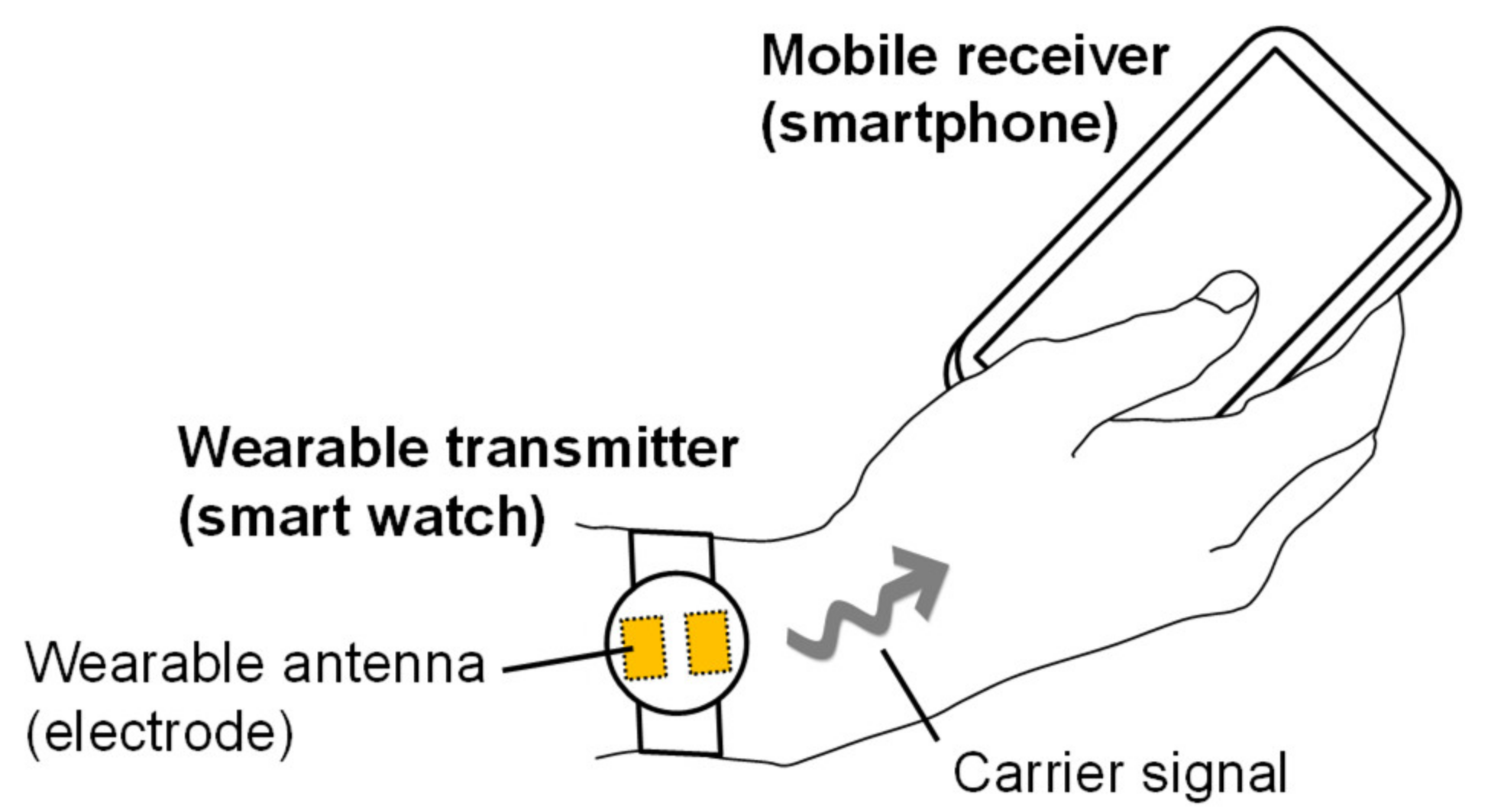
2. Proposed Human Body Communication System

In this study, we propose a human body communication system between a wearable transmitter (smart watch) worn on the wrist and a smartphone-sized receiver held in the hand. The antennas (electrodes) for these devices are assumed to be attached directly to the skin. Figure 1 shows the proposed HBC system. We focus on a carrier frequency of several MHz to several tens of MHz because (i) previous studies have reported that transmission efficiency peaks near 5 MHz [33], (ii) the frequency of 13.56 MHz has been assigned as an industrial, scientific, and medical (ISM) band [34], (iii) frequencies of 21 and 32 MHz have been assigned to HBC using the IEEE 802.15.6 standard [13], and (iv) frequencies of 40 and 68 MHz have been assigned to close capacitive coupling communication, which is the same technique as HBC, using the ISO/IEC 17982 standard [35].

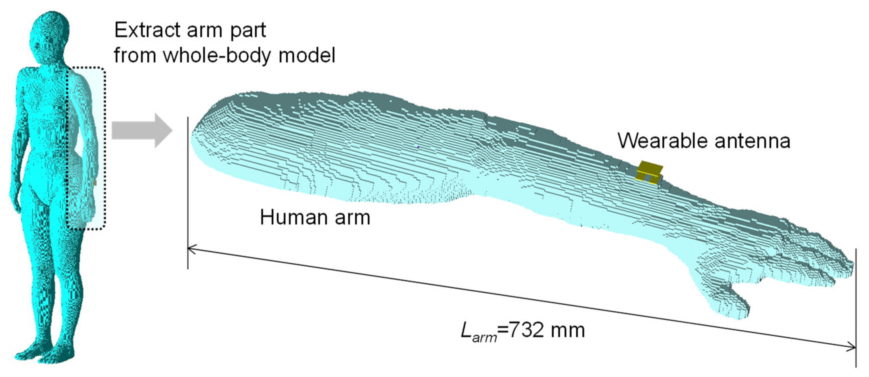
3. Models for Electromagnetic Field Simulation

The input impedance characteristics of the wearable antenna were calculated by an electromagnetic field simulation that was implemented by using the finite-difference time-domain (FDTD) method (XFdtd, Remcom Inc., PA, USA).
For the analytical investigation, we used an anatomically correct human body model. Figure 2 shows the realistic human arm model, which was extracted from the realistic high-resolution whole-body TARO model of a Japanese adult male. The wearable antenna was attached to the wrist of the model. For comparison, a realistic human arm model from the whole-body HANAKO model of a Japanese adult female was also used for FDTD simulations. The human body models were provided by the National Institute of Information and Communications Technology [36]. The models for the analysis include seven biological tissues: skin, fat, muscle, blood, tendon, and two types of bone. To investigate gender differences, the input impedance characteristics of wearable antennas were calculated for the male and female models. Frequency-dependent electrical properties of human tissue were applied to the realistic human arm models [37]. To analyze the effect of skin moisture, the electrical properties of dry and wet skin were used.
Figure 3 shows the structure of the wearable antenna prototype (i.e., wearable transmitter). The wearable antenna was placed on the wrist of the arm model. The transmitter consisted of a circuit board, a signal electrode, a ground electrode, connecting wires, and an excitation point between the circuit board and the signal electrode. The electrodes and circuit board were assumed to be perfect electric conductors (PECs). The entire bottom of the electrode was assumed to be in perfect contact with the realistic human arm model, with no gaps between the electrodes and skin layer. Because the surface of the realistic human arm model was not a smooth flat surface, we modeled the shape of the bottom of the electrodes to conform to the surface of the realistic human arm model so that the electrodes made perfect contact with the skin layer of the realistic human arm model.
The free-space padding of the FDTD simulations was 20 cells from the edge of the model, and the computing space was represented by nonuniform grids. The size of these grids gradually increased with increasing distance from the wearable antenna. The grid size was 1 mm near the wearable antenna and 5 mm at the edge of the computing space. A perfectly matched layer was used as an absorbing boundary. Seven layers were used. A broadband pulse was fed into the feeding point, which was between the signal electrode and the circuit board. The time step of the calculation was 1.798 ps.

4. Analytical Results Using the Realistic Arm Model

Figure 4 shows the input impedance characteristics of the wearable antenna calculated by the FDTD simulations using the male and female realistic arm models at frequencies ranging from 1 to 100 MHz. The solid and broken lines show the input impedance obtained from the male and female arm models, respectively. The black and red lines show the input impedance obtained from the dry and wet skin conditions, respectively. As shown in Figure 4, variations in input impedance between the male and female arm models are mostly at lower frequencies. For the dry skin condition, the variation in input impedance between the male and female arm models is less than 20%, whereas for the wet skin condition, the variation is less than 10%. Considering the reflection of high-frequency signals caused by variations in impedance, the variation in input impedance due to gender is sufficiently small. This means that the same antenna and circuit configuration can be used for males and females.
The variations in input impedance between dry and wet skin conditions increase as the frequency decreases. For the real part of the input impedance, the greatest variation caused by the skin condition is 53% at 1 MHz. For the imaginary part of the input impedance, the greatest variation is 80% at 1 MHz. However, above several MHz, moisture on the skin has little influence on the input impedance. To evaluate how impedance variations affect signal transmission, the voltage standing wave ratio (VSWR) at the feeding point was calculated as a key performance indicator of wearable antennas. The VSWR is an indication of the amount of mismatch between the impedance of the feeding point and the input impedance of the antenna. Generally, a VSWR value lower than two to three is considered to be suitable for most antenna systems [38]. The input impedance characteristics calculated by the male arm model with dry skin were applied to the output impedance of the feeding point. Above 4 MHz, the VSWR was calculated to be less than two, which fulfilled the VSWR criteria for good antennas. This implies that the influence of skin moisture can be reduced by selecting a suitable carrier frequency and output impedance for the feeding point.

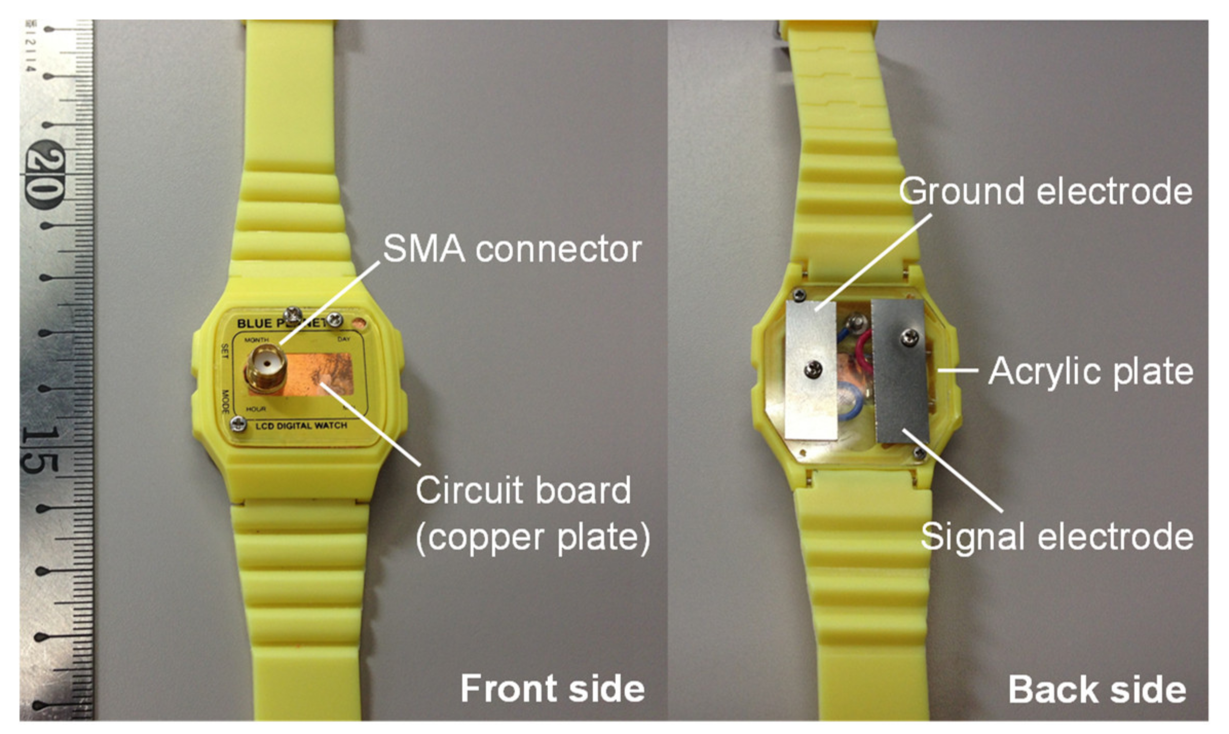
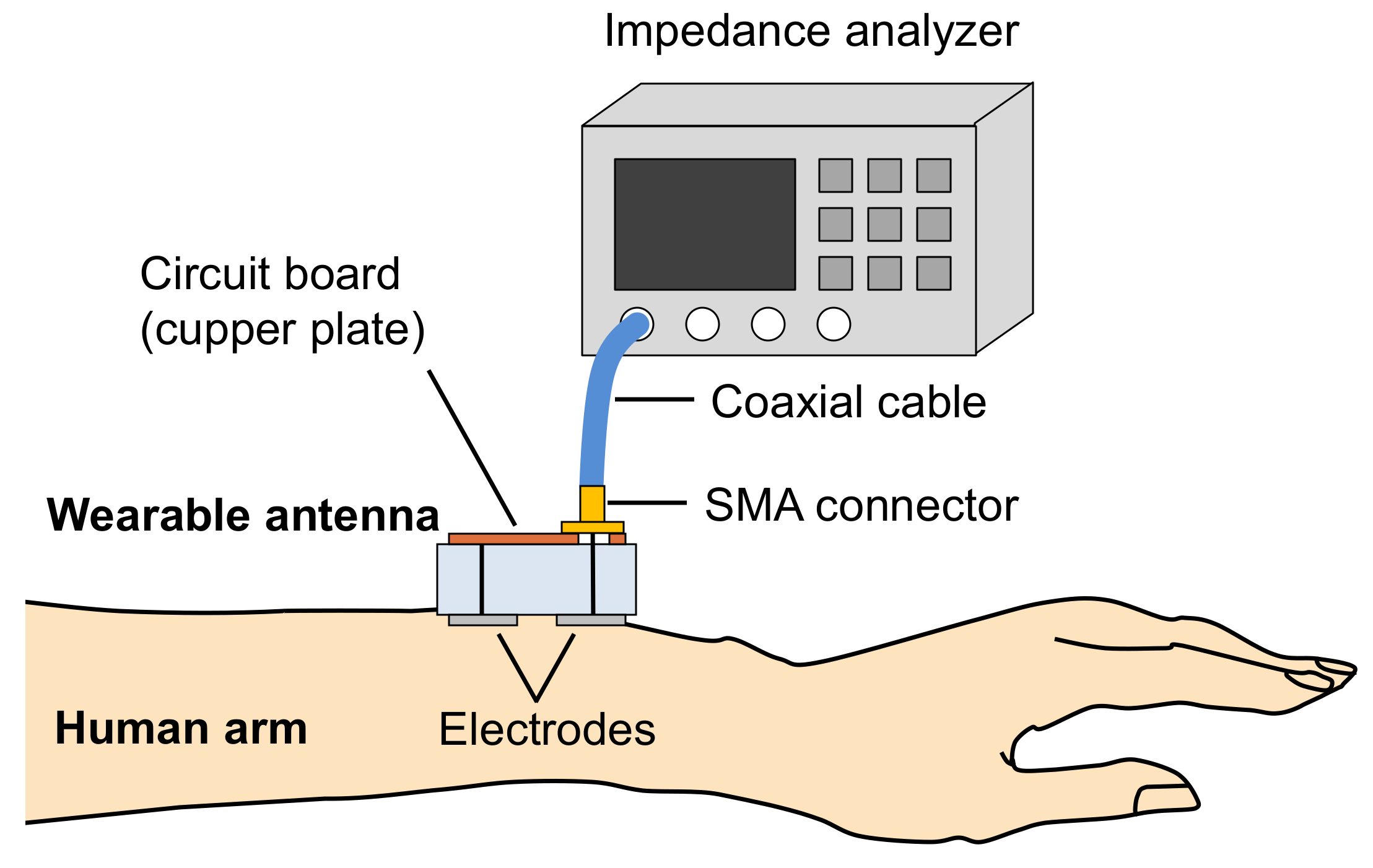
5. Measurement System and Real Human Subjects

The electrode unit of the wearable transmitter for the experiment is shown in Figure 5. It is composed of a copper plate to simulate a circuit board, a signal electrode, a ground electrode, connecting wires, and an SMA connector for feeding transmission signals from a signal generator. The signal and ground electrodes are connected to the inner and outer conductor of the SMA connector, respectively. The electrodes are made of thin stainless-steel plates. The size of the electrodes is the same as for the wearable antenna shown in Figure 3. Figure 6 shows the measurement system used to measure the input impedance characteristics of the wearable antenna worn on the left wrist of real human subjects. Input impedance characteristics were measured by using an impedance analyzer (4294A, Agilent, CA, USA) connected to the antenna prototype. In this experiment, we measured the input impedance of 22 human subjects. Subjects A–L were Japanese males from 20 to 30 years old, and subjects M–V were Japanese females from 20 to 30 years old. The average age of all subjects was 26.3 years, and the standard deviation was 4.6 years. During the real human subject experiment, room temperature and humidity were maintained at 20–24 °C and 40–60%, respectively. The room conditions were kept comfortable so that the subjects would not sweat.
This study was approved by the Research Ethics Committee of the University of Tokyo, and the participants’ written informed consent was obtained prior to starting the study.

6. Measurement Results

Figure 7 and Figure 8 show the input impedance characteristics of the wearable antenna obtained from twelve male subjects A–L and ten female subjects M–V. The fine solid lines show the values measured when the subjects wore the wearable antenna. The bold broken lines show the values calculated by the FDTD simulations. Figure 7 and Figure 8 show that the overall frequency characteristics of analytical and experimental results were similar at frequencies ranging from 1 to 100 MHz. This similarity shows the validity of FDTD simulations using the realistic human arm model. We confirmed that slight changes in the position and contact strength of the wearable antenna do not affect the input impedance characteristics measured by the same subject.
Variations in input impedance among the subjects are greater at lower frequencies because the electric current flows mainly at the surface of the arm at a higher frequency due to the skin effect, whereas at lower frequencies, more electric current flows through the inner tissues of the arm. Inner structure and thickness of biological tissues differ according to individual subjects. Therefore, individual variations in the thickness of the skin and fat layers can significantly influence impedance characteristics at low frequency. This influence is discussed in detail through the analysis considering tissue structure in Section 7.
To evaluate how the impedance variations shown in Figure 7 and Figure 8 affect signal transmission, the VSWR was calculated, as described in Section 4. The average values of input impedance obtained from the dry- and wet-skin conditions for the male arm model were applied to the output impedance of the feeding point. To calculate the worst values of the VSWR, we selected the subject whose input impedance characteristics deviated most from the output impedance of the feeding point. One subject was selected from each of the male and female subject groups. As shown in Figure 9, the worst values of the VSWR were 2.87 and 2.03 at 1 MHz for the male and female subjects, respectively. A VSWR value less than three is acceptable for most antenna systems. Moreover, the VSWR was calculated to be less than two above 5 MHz. This implies that frequencies above 5 MHz are suitable for a carrier frequency to reduce the impedance mismatch in the feeding point. These results revealed that HBC is robust against the variations of individual users.

7. Influence of Tissue Structure

7.1. Development of the Simplified Arm Model

In Section 6, the subject experiment showed that individual variations in tissue structure can significantly influence impedance characteristics. To evaluate the influence of the thickness of skin and fat layers on the impedance characteristics, we changed the structure of the simulation model. However, changing the composition or posture of the realistic human arm models is difficult because of their intricate tissue design. In our previous studies, skin, fat, and muscle were the dominant types of body tissues that determined the input impedance of a wearable antenna at 10 MHz. Other body tissues below the muscle had little influence on the input impedance because the electric current was small in those tissues [26]; therefore, we created a simplified arm model in which the tissue structures could be changed.
First, we changed the realistic human arm model into a three-tissue model, without changing its shape, by changing the electrical characteristics of the blood, tendon, and bone parts to that of the muscle. We compared the input impedance characteristics of the wearable antenna between the original arm model and the three-tissue model over a frequency range from 1 to 100 MHz. Figure 10 compares the input impedance characteristics calculated from the original seven-tissue arm model and the three-tissue model at frequencies ranging from 1 to 100 MHz. The solid lines and broken lines show the input impedance obtained from the seven-tissue model and the three-tissue model, respectively. The black and red lines show the real and imaginary components of the input impedance, respectively. As shown in Figure 10, the variations in input impedance between the two models are very small over the entire frequency range. This result shows that skin, fat, and muscle are the dominant body tissues that determine the impedance characteristics.
Next, the shape of the arm model was reduced to a simple rectangular prism. Figure 11 shows the structure of the simplified model for the input impedance calculation. The thickness of the skin layer, ds, was varied from 0.5 to 1.5 mm, and the thickness of the fat layer, df, was varied from 2 to 4 mm. The range of variation considers the differences among individuals for each tissue thickness [39,40]. Dry skin and wet skin conditions were both considered in the model. Input impedance characteristics with changes in the thickness of the skin and fat layers are shown in Figure 12 (with dry skin) and in Figure 13 (with wet skin). Considering ds is 1 mm and df is 3 mm, the input impedance characteristics calculated by the rectangular prism model were in good agreement with those calculated using the seven-tissue model. These input impedance characteristics show that a thinner skin layer and a thicker fat layer have higher input impedance. This result is explained by the electrical conductivity of fat being lower than that of skin and muscle. Moreover, the input impedance calculated by the rectangular prism model with a variety of tissue thicknesses is distributed around the input impedance obtained from the seven-tissue model.

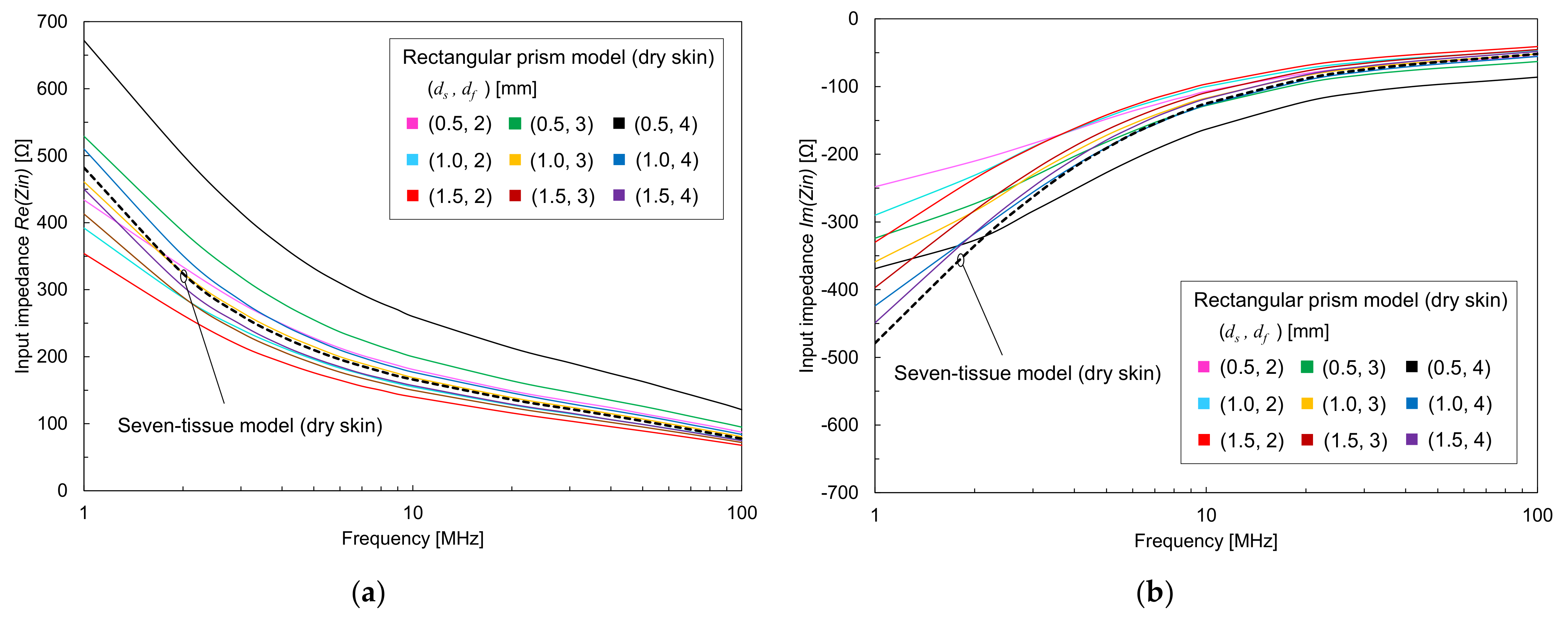
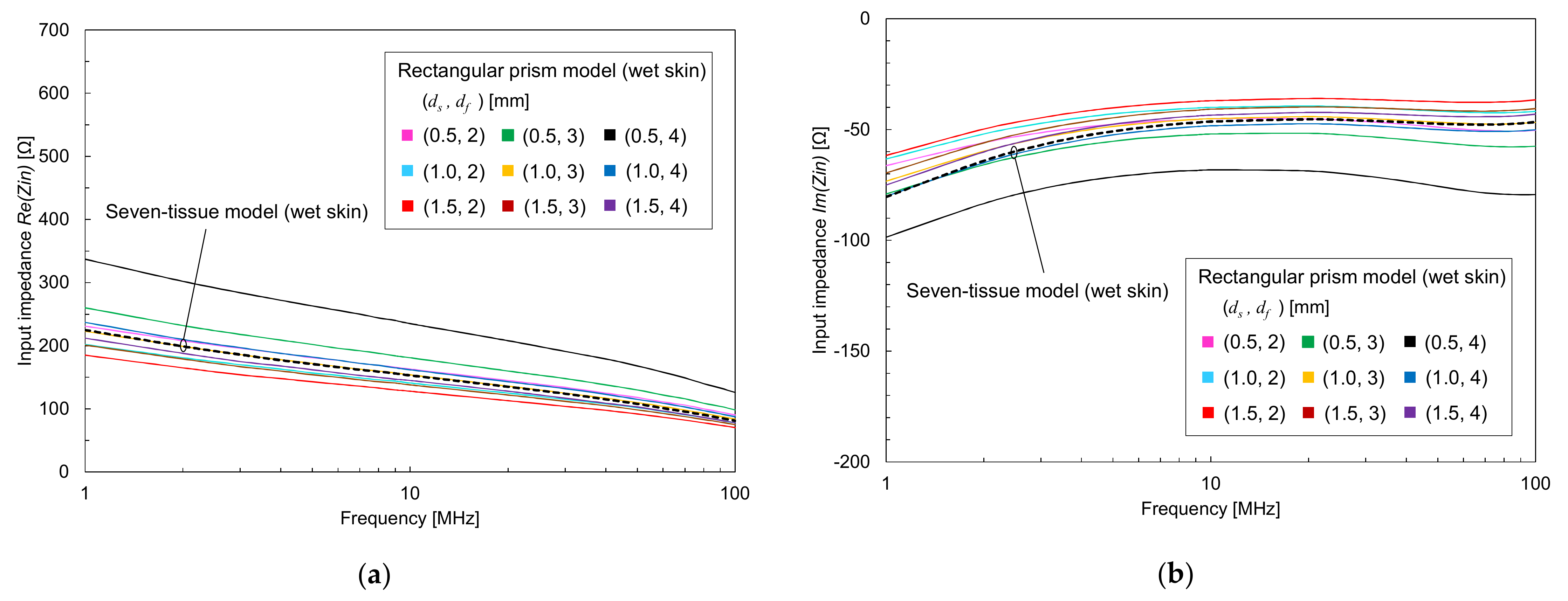
7.2. Measured Impedance Compared with Calculated Impedance for Various Thicknesses of Skin and Fat Layers

Figure 14 compares the measured input impedance characteristics with the calculated impedance characteristics of the rectangular prism model with various thicknesses of skin and fat layers, which were in the same range as those in Figure 12 and Figure 13. As shown in Figure 14, the impedance distributions obtained from the rectangular prism model cover almost all values measured from the real human subjects. This implies that one of the reasons for the variations in measured input impedance is the tissue structure of the individual subjects. In addition, the rectangular prism model can estimate the impedance fluctuations caused by the individual users without multiple subject experiments because the model covers the impedance variations caused by individual users. The results also suggest the utility of the rectangular prism model in the development phase of an antenna and device.

8. Conclusions

In this study, we discuss the input impedance characteristics of a wearable antenna based on analyses of realistic human arm models and real human subjects from the viewpoint of the impedance fluctuations caused by the physiological variations of individual users. Initially, the input impedance characteristics are calculated by using a realistic human arm model wearing a wearable antenna prototype. The variation in input impedance due to gender is relatively small. The moisture condition of the skin somewhat affects the input impedance at the low-frequency range; however, above several MHz, this has little influence on the input impedance from the viewpoint of the VSWR. In the next step, input impedance measurements based on the wearable antenna prototype and real human subjects are demonstrated to investigate individual differences. Analytical and experimental results showed the same tendency over the frequency range from 1 to 100 MHz. The worst value of the VSWR calculated from the subject experiment was less than three, which is an acceptable value for most antenna systems. In addition, to clarify the variation in input impedance caused by the characteristics of each real human subject, we devised a simplified rectangular prism model. The impedance distributions obtained from the rectangular prism model covered almost all values measured on the human subjects. This implies that one of the reasons for the variations in measured input impedance is the tissue structure of individual subjects. In addition, the rectangular prism model enables us to design the antenna prototype without multiple subject experiments. The results of this study reveal the feasibility of HBC from the point of view of the robustness of wearable antennas against the influences of individual users (i.e., variations in tissue structure and skin moisture). The findings also provide useful insights for the design of HBC systems, such as front-end circuits connected to an antenna device and frequency bands for communication.

Author Contributions

Conceptualization, D.M.; data curation, D.M.; formal analysis, D.M; funding acquisition, D.M.; investigation, D.M.; methodology, D.M.; project administration, D.M.; supervision, K.S.; writing—original draft, D.M.; writing—review and editing, K.S. All authors have read and agreed to the published version of the manuscript.

Funding

A part of this research was funded by a Grant-in-Aid for Young Scientists (A)17H04929.

Institutional Review Board Statement

This study was approved by the Research Ethics Committee of the University of Tokyo (12-88, 28 May 2013).

Informed Consent Statement

Informed consent was obtained from every subject involved in the study.

Data Availability Statement

The data presented in this study are available on request from the corresponding author. The data are not publicly available due to privacy.

Conflicts of Interest

The authors declare no conflict of interest.

References

  1. Weiser, M. The Computer for the 21st Century. Sci. Am. 1991. [Google Scholar] [CrossRef]
  2. CES. 2021. Available online: https://www.ces.tech/ (accessed on 4 May 2021).
  3. Lara, O.D.; Labrador, M.A. A Survey on Human Activity Recognition Using Wearable Sensors. IEEE Commun. Surv. Tutor. 2013, 15, 1192–1209. [Google Scholar] [CrossRef]
  4. Pernek, I.; Kurillo, G.; Stiglic, G.; Bajcsy, R. Recognizing the Intensity of Strength Training Exercises with Wearable Sensors. J. Biomed. Inform. 2015, 58, 145–155. [Google Scholar] [CrossRef] [Green Version]
  5. Yin, J.; Yang, Q.; Pan, J.J. Sensor-Based Abnormal Human-Activity Detection. IEEE Trans. Knowl. Data Eng. 2008, 20, 1082–1090. [Google Scholar] [CrossRef]
  6. Pantelopoulos, A.; Bourbakis, N.G. A Survey on Wearable Sensor-Based Systems for Health Monitoring and Prognosis. IEEE Trans. Syst. Man Cybern. C 2010, 40, 1–12. [Google Scholar] [CrossRef] [Green Version]
  7. Asada, H.H.; Shaltis, P.; Reisner, A.; Rhee, S.; Hutchinson, R.C. Mobile Monitoring with Wearable Photoplethysmographic Biosensors. IEEE Eng. Med. Biol. Mag. 2003, 22, 28–40. [Google Scholar] [CrossRef] [PubMed] [Green Version]
  8. Takamatsu, R.; Higuchi, K.; Muramatsu, D. Measurement Frequency Evaluation for Bioimpedance-Based Blood-Glucose Estimation. In Proceedings of the 2021 IEEE 3rd Global Conference on Life Sciences and Technologies (LifeTech), Nara, Japan, 9–11 March 2021; pp. 309–310. [Google Scholar]
  9. Ali, H.; Bensaali, F.; Jaber, F. Novel Approach to Non-Invasive Blood Glucose Monitoring Based on Transmittance and Refraction of Visible Laser Light. IEEE Access 2017, 5, 9163–9174. [Google Scholar] [CrossRef]
  10. Jin, H.; Abu-Raya, Y.S.; Haick, H. Advanced Materials for Health Monitoring with Skin-Based Wearable Devices. Adv. Healthc. Mater. 2017, 6, 1700024. [Google Scholar] [CrossRef]
  11. Cao, H.; Leung, V.; Chow, C.; Chan, H. Enabling Technologies for Wireless Body Area Networks: A Survey and Outlook. IEEE Commun. Mag. 2009, 47, 84–93. [Google Scholar] [CrossRef]
  12. Movassaghi, S.; Abolhasan, M.; Lipman, J.; Smith, D.; Jamalipour, A. Wireless Body Area Networks: A Survey. IEEE Commun. Surv. Tutor. 2014, 16, 1658–1686. [Google Scholar] [CrossRef]
  13. IEEE Standard for Local and Metropolitan Area Networks—Part 15.6: Wireless Body Area Networks; IEEE Std 802.15.6-2012; Institute of Electrical and Electronics Engineers: New York, NY, USA, 2012; pp. 1–271. [CrossRef]
  14. Zimmerman, T.G. Personal Area Networks: Near-Field Intrabody Communication. IBM Syst. J. 1996, 35, 609–617. [Google Scholar] [CrossRef] [Green Version]
  15. Salonen, P.; Rahmat-Samli, Y. Effects of Antenna Bending on Input Matching and Impedance Bandwidth. IEEE Aerosp. Electron. Syst. Mag. 2007, 22, 18–22. [Google Scholar] [CrossRef]
  16. Mahmud, S.; Dey, S.; Saha, N. Super Wide Band Wearable Antenna: Assessment of the Conformal Characteristics in Terms of Impedance Matching and Radiation Properties. In Proceedings of the 2012 International Symposium on Antennas and Propagation (ISAP), Nagoya, Japan, 29 October 2012; pp. 563–566. [Google Scholar]
  17. Jeong, J.; Park, K.; Lee, C. Design of Cavity-Backed Bow-Tie Antenna with Matching Layer for Human Body Application. Sensors 2019, 19, 4015. [Google Scholar] [CrossRef] [PubMed] [Green Version]
  18. Dissanayake, T.; Esselle, K.P.; Yuce, M.R. Dielectric Loaded Impedance Matching for Wideband Implanted Antennas. IEEE Trans. Microw. Theory Tech. 2009, 57, 2480–2487. [Google Scholar] [CrossRef] [Green Version]
  19. Kim, I.; Lee, S.-G.; Nam, Y.-H.; Lee, J.-H. Investigation on Wireless Link for Medical Telemetry Including Impedance Matching of Implanted Antennas. Sensors 2021, 21, 1431. [Google Scholar] [CrossRef] [PubMed]
  20. Bae, J.; Song, K.; Lee, H.; Cho, H.; Yoo, H.-J. A 0.24-NJ/b Wireless Body-Area-Network Transceiver With Scalable Double-FSK Modulation. IEEE J. Solid State Circuits 2012, 47, 310–322. [Google Scholar] [CrossRef]
  21. Mao, J.; Yang, H.; Lian, Y.; Zhao, B. A Self-Adaptive Capacitive Compensation Technique for Body Channel Communication. IEEE Trans. Biomed. Circuits Syst. 2017, 11, 1001–1012. [Google Scholar] [CrossRef]
  22. Wang, H.; Tang, X.; Choy, C.S.; Leung, K.N.; Pun, K.P. A 5.4-MW 180-Cm Transmission Distance 2.5-Mb/s Advanced Techniques-Based Novel Intrabody Communication Receiver Analog Front End. IEEE Trans. VLSI Syst. 2015, 23, 2829–2841. [Google Scholar] [CrossRef]
  23. Wang, H.; Tang, X.; Choy, C.S.; Sobelman, G.E. Cascaded Network Body Channel Model for Intrabody Communication. IEEE J. Biomed. Health Inform. 2016, 20, 1044–1052. [Google Scholar] [CrossRef]
  24. Kazim, M.I.; Kazim, M.I.; Wikner, J.J. Complex Path Impedance Estimation and Matching Requirements for Body-Coupled Communication. In Proceedings of the 2015 European Conference on Circuit Theory and Design (ECCTD), Trondheim, Norway, 24 August 2015; pp. 1–4. [Google Scholar]
  25. Nishida, Y.; Sasaki, K.; Yamamoto, K.; Muramatsu, D.; Koshiji, F. Equivalent Circuit Model Viewed From Receiver Side in Human Body Communication. IEEE Trans. Biomed. Circuits Syst. 2019, 13, 746–755. [Google Scholar] [CrossRef] [PubMed]
  26. Muramatsu, D.; Koshiji, F.; Koshiji, K.; Sasaki, K. Input Impedance Analysis of a Human Body Communication Transmitter Using a Realistic Human Model and a Simplified Layered Model. Trans. Jpn. Inst. Electron. Packag. 2013, 16, 528–534. [Google Scholar] [CrossRef] [Green Version]
  27. Muramatsu, D.; Koshiji, F.; Koshiji, K.; Sasaki, K. Analytical and Experimental Studies on Human Body Communication between Wristwatch and Handheld Devices Using Muscle Homogenous Phantom at 10 MHz. Sens. Mater. 2014, 26, 9. [Google Scholar]
  28. Fujii, K.; Takahashi, M.; Ito, K. Electric Field Distributions of Wearable Devices Using the Human Body as a Transmission Channel. IEEE Trans. Antennas Propagat. 2007, 55, 2080–2087. [Google Scholar] [CrossRef]
  29. Haga, N.; Saito, K.; Takahashi, M.; Ito, K. Equivalent Circuit of Intrabody Communication Channels Inducing Conduction Currents Inside the Human Body. IEEE Trans. Antennas Propagat. 2013, 61, 2807–2816. [Google Scholar] [CrossRef]
  30. Yamamoto, K.; Nishida, Y.; Sasaki, K.; Muramatsu, D.; Koshiji, F. Electromagnetic Field Analysis of Signal Transmission Path and Electrode Contact Conditions in Human Body Communication. Appl. Sci. 2018, 8, 1539. [Google Scholar] [CrossRef] [Green Version]
  31. Maity, S.; He, M.; Nath, M.; Das, D.; Chatterjee, B.; Sen, S. Bio-Physical Modeling, Characterization, and Optimization of Electro-Quasistatic Human Body Communication. IEEE Trans. Biomed. Eng. 2019, 66, 1791–1802. [Google Scholar] [CrossRef] [Green Version]
  32. Muramatsu, D.; Koshiji, F.; Koshiji, K.; Sasaki, K. Input Impedance Analysis of Wearable Antenna and Its Experimental Study with Real Human Body. In Proceedings of the 2014 IEEE International Conference on Consumer Electronics (ICCE), Las Vegas, NV, USA, 10 January 2014; pp. 151–152. [Google Scholar]
  33. Hachisuka, K.; Nakata, A.; Takeda, T.; Shiba, K.; Sasaki, K.; Hosaka, H.; Itao, K. Development of Wearable Intra-Body Communication Devices. Sens. Actuators A Phys. 2003, 105, 109–115. [Google Scholar] [CrossRef]
  34. International Telecommunication Union. Available online: http://www.itu.int/en/pages/default.aspx (accessed on 4 May 2021).
  35. International Standard ISO/IEC 17982 Information Technology—Telecommunications and Information Exchange between Systems—Close Capacitive Coupling Communication Physical Layer (CCCC PHY); Technical Committee—ISO/IEC JTC 1/SC 6 Telecommunications and Information Exchange Between Systems: Geneva, Switzerland, 2012; pp. 1–48.
  36. Nagaoka, T.; Watanabe, S.; Sakurai, K.; Kunieda, E.; Watanabe, S.; Taki, M.; Yamanaka, Y. Development of Realistic High-Resolution Whole-Body Voxel Models of Japanese Adult Males and Females of Average Height and Weight, and Application of Models to Radio-Frequency Electromagnetic-FIeld Dosimetry. Phys. Med. Biol. 2004, 49, 1–15. [Google Scholar] [CrossRef] [PubMed]
  37. Gabriel, S.; Lau, R.W.; Gabriel, C. The Dielectric Properties of Biological Tissues: II. Measurements in the Frequency Range 10 Hz to 20 GHz. Phys. Med. Biol. 1996, 41, 2251–2269. [Google Scholar] [CrossRef] [PubMed] [Green Version]
  38. Nakano, H.; Ikeda, N.; Wu, Y.-Y.; Suzuki, R.; Mimaki, H.; Yamauchi, J. Realization of Dual-Frequency and Wide-Band VSWR Performances Using Normal-Model Helical and Inverted-F Antennas. IEEE Trans. Antennas Propagat. 1998, 46, 788–793. [Google Scholar] [CrossRef]
  39. Southwood, W.F.W. The Thickness of the Skin. Plast. Reconstr. Surg. 1955, 15, 423–429. [Google Scholar] [CrossRef] [PubMed]
  40. Gordon, R.G.; Roemer, R.B.; Horvath, S.M. A Mathematical Model of the Human Temperature Regulatory System—Transient Cold Exposure Response. IEEE Trans. Biomed. Eng. 1976, BME-23, 434–444. [Google Scholar] [CrossRef] [PubMed]
Figure 1. Proposed human body communication system.
Electronics 10 01152 g001
Figure 2. Realistic human arm model.
Electronics 10 01152 g002
Figure 3. Structure of the wearable antenna prototype.
Electronics 10 01152 g003
Figure 4. Input impedance characteristics of a wearable antenna calculated for a realistic human body model: (a) Real component of input impedance characteristics; (b) imaginary component of input impedance characteristics.
Electronics 10 01152 g004
Figure 5. Make-up of the wearable antenna prototype.
Electronics 10 01152 g005
Figure 6. System for measuring wearable antenna.
Electronics 10 01152 g006
Figure 7. Input impedance characteristics of the wearable antenna measured by using male subjects: (a) Real component of input impedance characteristics; (b) imaginary component of input impedance characteristics.
Electronics 10 01152 g007
Figure 8. Input impedance characteristics of the wearable antenna measured by using female subjects: (a) Real component of input impedance characteristics; (b) imaginary component of input impedance characteristics.
Electronics 10 01152 g008
Figure 9. The worst values of the VSWR calculated using the input impedance characteristics obtained from the subject experiment.
Electronics 10 01152 g009
Figure 10. Input impedance characteristics of the wearable antenna calculated by using a seven-tissue model and a three-tissue model.
Electronics 10 01152 g010
Figure 11. Simplified rectangular prism model.
Electronics 10 01152 g011
Figure 12. Input impedance characteristics of the wearable antenna calculated by using a simplified rectangular prism model with dry skin: (a) Real component of input impedance characteristics; (b) imaginary component of input impedance characteristics.
Electronics 10 01152 g012
Figure 13. Input impedance characteristics of the wearable antenna calculated by using a simplified rectangular prism model with wet skin: (a) Real component of input impedance characteristics; (b) imaginary component of input impedance characteristics.
Electronics 10 01152 g013
Figure 14. Comparison of input impedance characteristics obtained from measurement and from analysis: (a) Real component of input impedance characteristics; (b) imaginary component of input impedance characteristics.
Electronics 10 01152 g014
Publisher’s Note: MDPI stays neutral with regard to jurisdictional claims in published maps and institutional affiliations.

