Ultra-Wideband MIMO Array for Penetrating Lunar Regolith Structures on the Chang’e-5 Lander

 ,
,
Abstract
:1. Introduction
2. Antenna Design Requirements
3. MIMO Array System Design
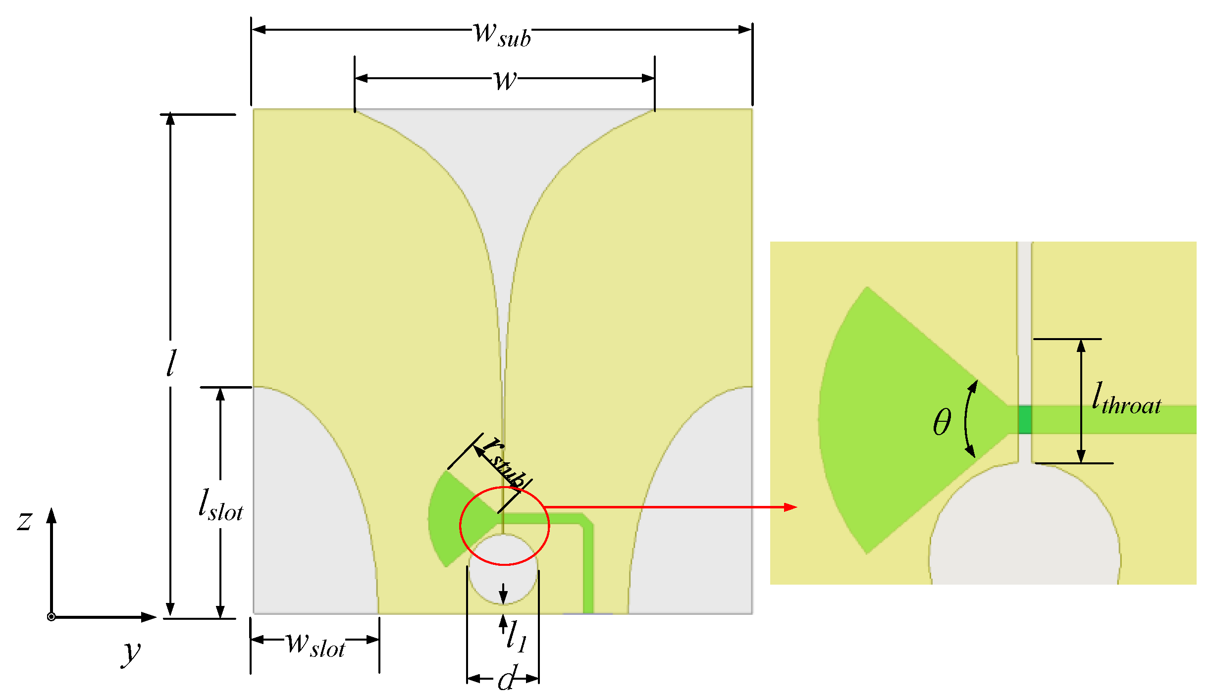
3.1. Antenna Element Design
3.2. Array Design
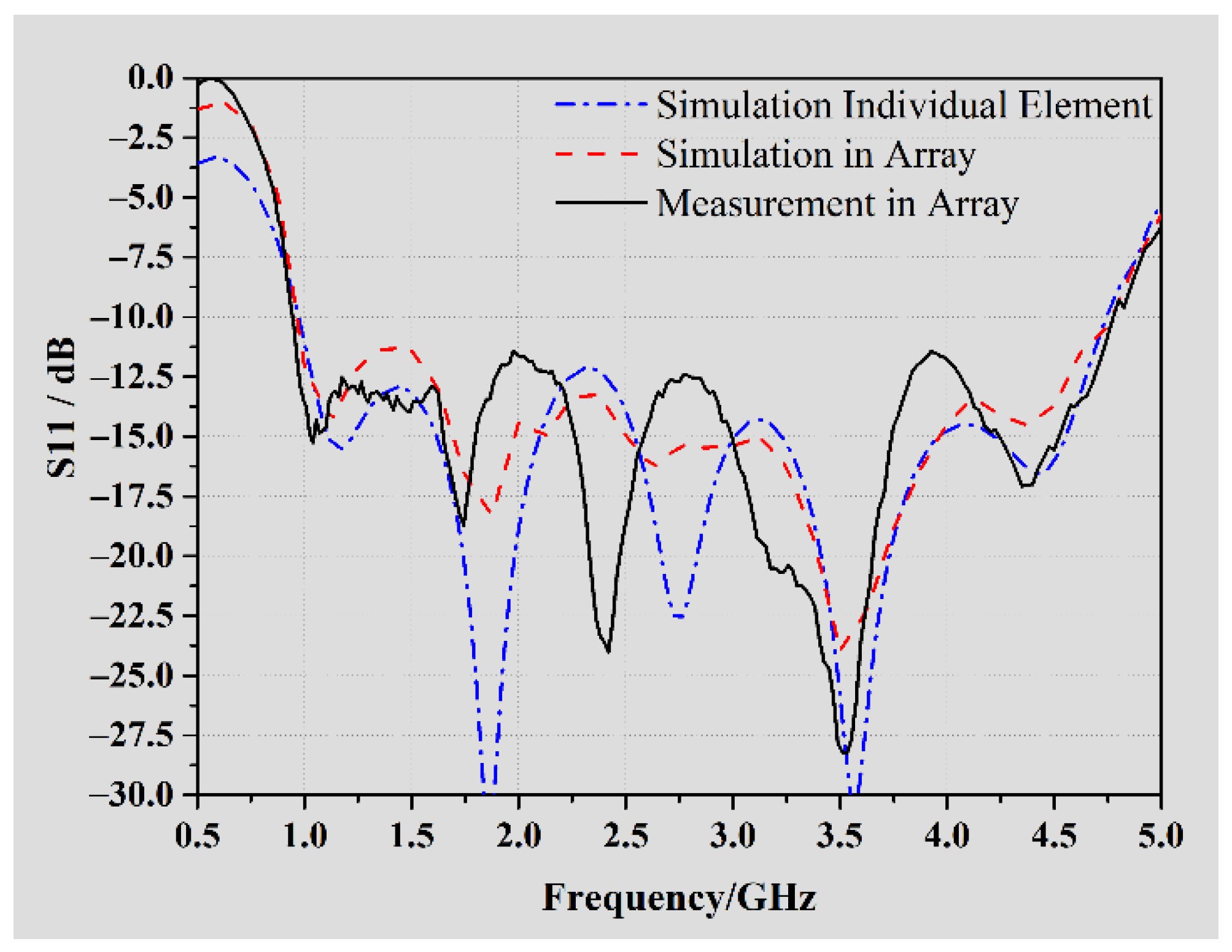
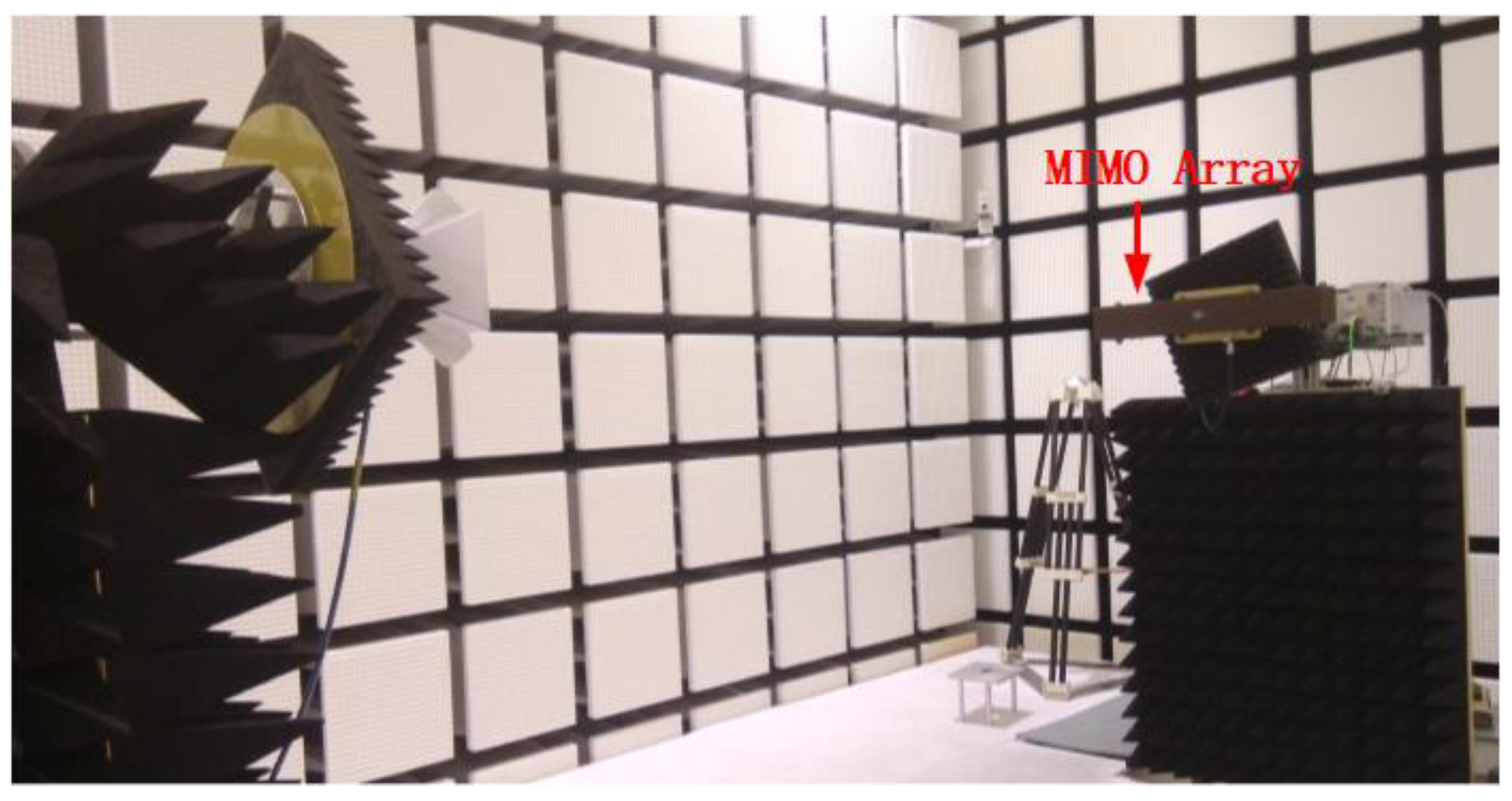
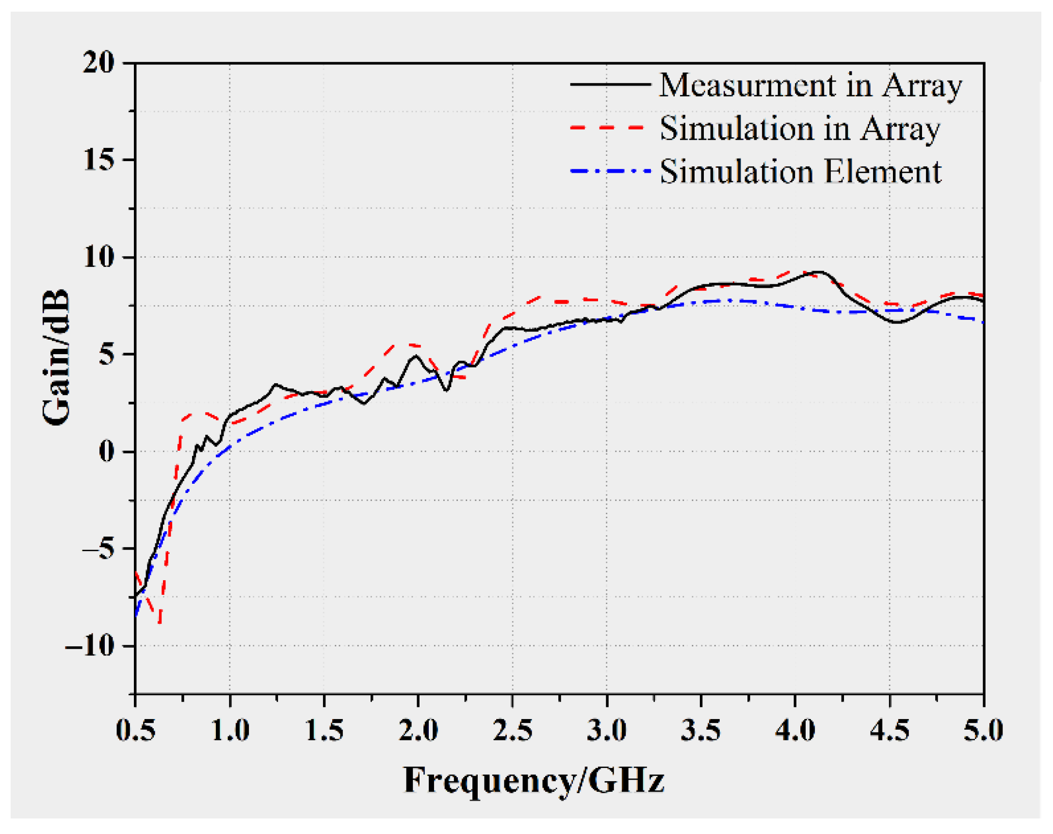
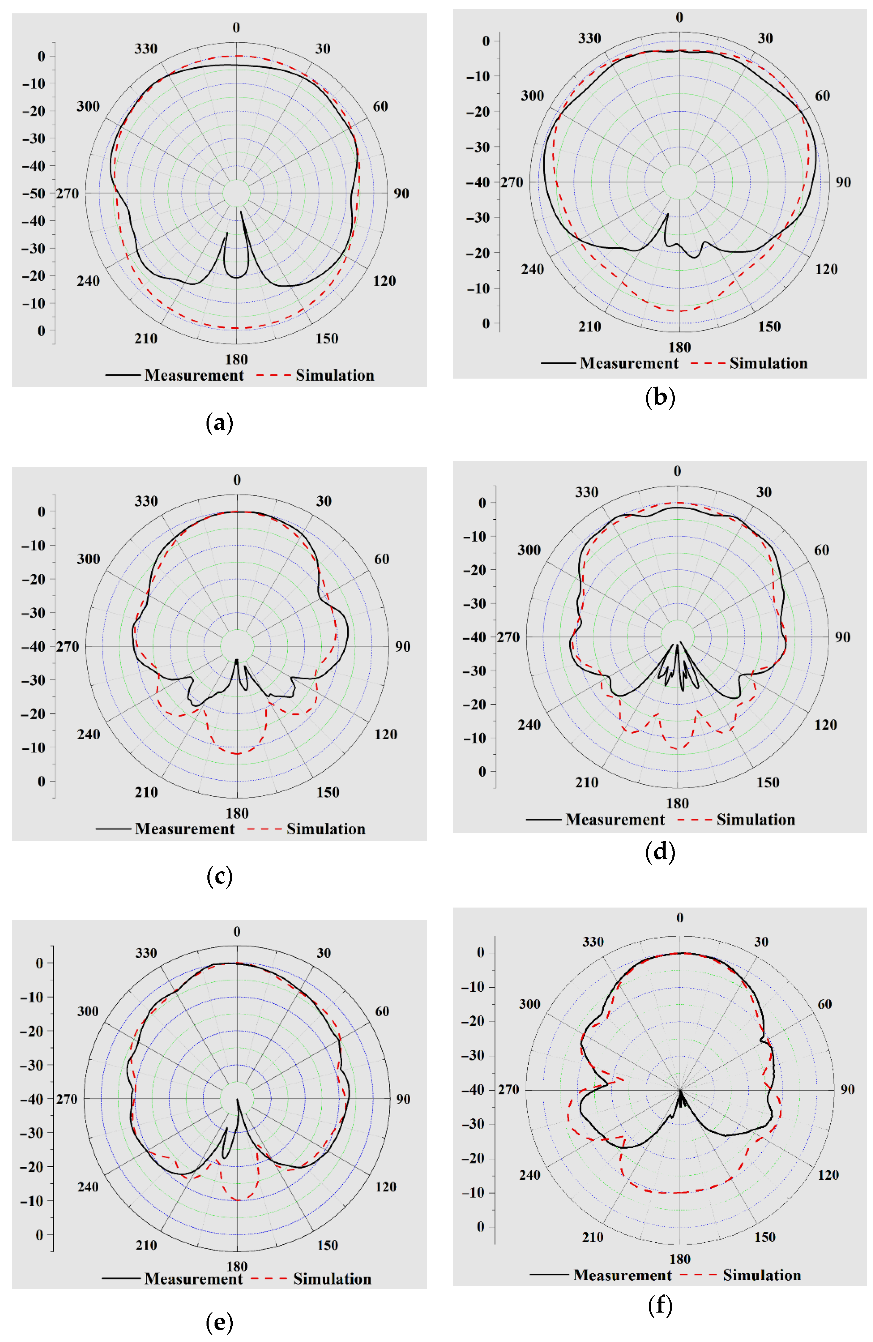
3.3. Simulation and Measurement
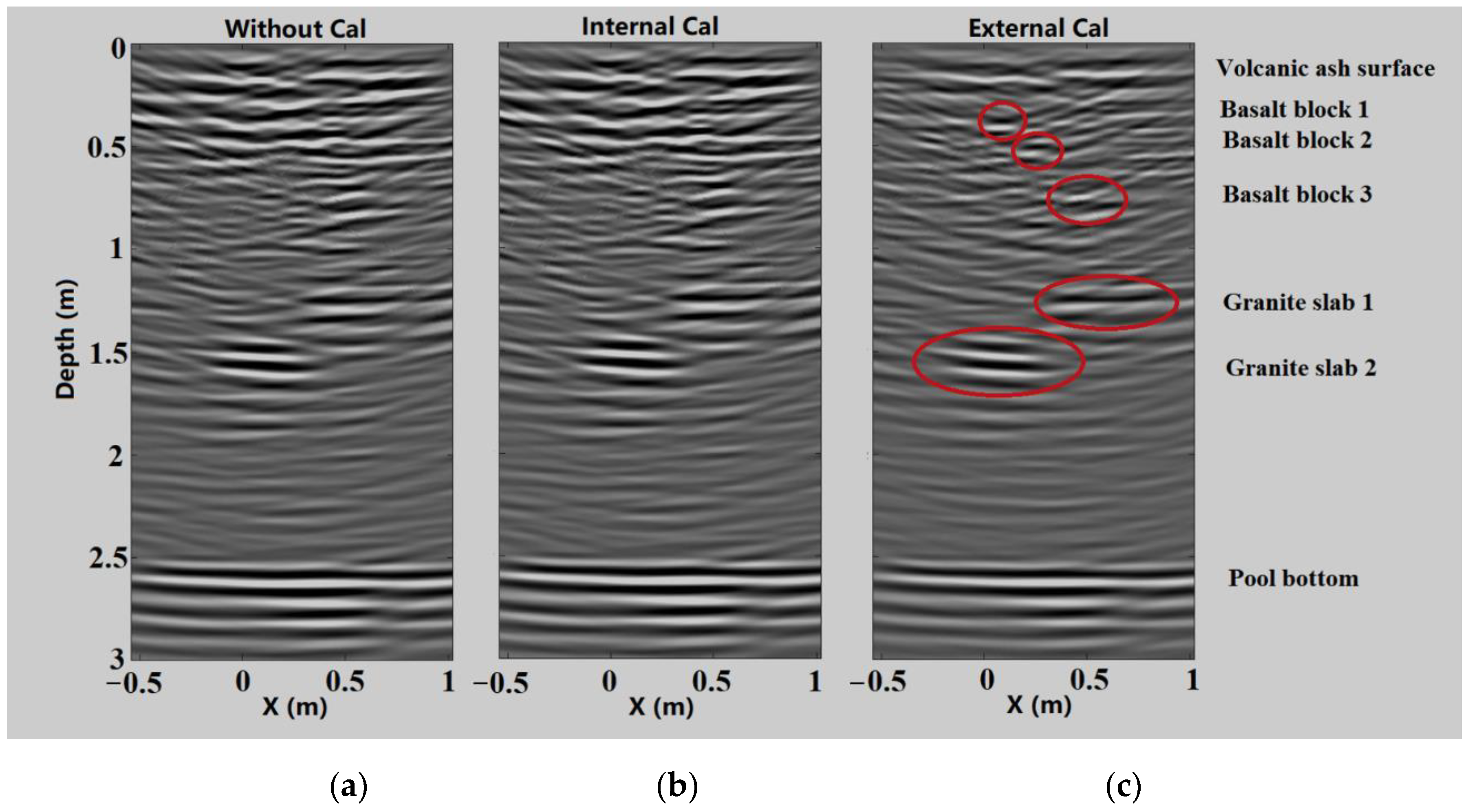
4. Calibration and Experimental Validation
5. Discussion
6. Conclusions
Author Contributions
Funding
Acknowledgments
Conflicts of Interest
References
- Porcello, L.J.; Jordan, R.L.; Zelenka, J.S.; Adams, G.F.; Phillips, R.J.; Brown, W.E.; Ward, S.H.; Jackson, P.L. The Apollo lunar sounder radar system. Proc. IEEE 1974, 62, 769–783. [Google Scholar] [CrossRef]
- Kobayashi, T.; Lee, S.R.; Kumamoto, A.; Ono, T. GPR observation of the Moon from orbit: Kaguya Lunar Radar Sounder. In Proceedings of the 15th International Conference on Ground Penetrating Radar, GPR 2014, Brussels, Belgium, 30 June–4 July 2014; pp. 1037–1041. [Google Scholar]
- Fang, G.; Zhou, B.; Ji, Y.; Zhang, Q.; Shen, S.; Li, Y.; Guan, H.; Tang, C.; Gao, Y.; Lu, W.; et al. Lunar Penetrating Radar onboard the Chang’e-3 mission. Res. Astron. Astrophys. 2014, 14, 1607–1622. [Google Scholar] [CrossRef]
- Lai, J.; Xu, Y.; Zhang, X.; Xiao, L.; Yan, Q.; Meng, X.; Zhou, B.; Dong, Z.; Zhao, D. Comparison of Dielectric Properties and Structure of Lunar Regolith at Chang’e-3 and Chang’e-4 Landing Sites Revealed by Ground-Penetrating Radar. Geophys. Res. Lett. 2019, 46, 12783–12793. [Google Scholar] [CrossRef]
- Zhou, B.; Li, Y.; Li, D.; Lu, W.; Shen, S.; Fang, G.; Su, Y.; Dai, S. Initial Laboratory Field Tests of the Rover-mounted GPR for China’s First Mission to Mars. In Proceedings of the 2018 17th International Conference on Ground Penetrating Radar (GPR), Rapperswil, Switzerland, 18–21 June 2018. [Google Scholar]
- Hamran, S.; Berger, T.; Brovoll, S.; Damsgård, L.; Helleren, Ø.; Øyan, M.J.; Amundsen, H.E.; Carter, L.; Ghent, R.; Kohler, J.; et al. RIMFAX: A GPR for the Mars 2020 rover mission. In Proceedings of the 2015 8th International Workshop on Advanced Ground Penetrating Radar (IWAGPR), Florence, Italy, 7–10 July 2015. [Google Scholar]
- Zou, L.; Kikuta, K.; Sato, M. Nondestructive Inspection of an Airport Pavement by MIMO Array GPR YAKUMO. In Proceedings of the 2018 17th International Conference on Ground Penetrating Radar (GPR), Rapperswil, Switzerland, 18–21 June 2018. [Google Scholar]
- Panzer, B. Development of an Electrically Small Vivaldi Antenna: The CReSIS Aerial Vivaldi(CAV-A). Master’s Thesis, University of Kansas, Lawrence, KS, USA, 2004. [Google Scholar]
- Lee, R.Q. NASA Tech Memorandum NASA/TM-2004-213057. Notch Antenna; Glenn Research Center: Cleveland, OH, USA, 2004.
- Lee, K.F.; Chen, W. Advances in Microstrip and Printed Antennas. In Advances in Microstrip and Printed Antennas; Lee, K.F., Chen, W., Eds.; Publishing House: New York, NY, USA, 1997; pp. 443–514. [Google Scholar]
- Schaubert, D.H.; Chio, T.; Holter, H. TSA element design for 50–1500 MHz array. In Proceedings of the IEEE Antennas and Propagation Society International Symposium, Salt Lake City, UT, USA, 16–21 July 2000; Volume 1, pp. 178–181. [Google Scholar]
- Yektakhah, B. High Resolution Through-the-Wall and Subsurface Imaging Using Small Number of Transceivers on Moving Robotic Platforms. Ph.D. Thesis, University of Michigan, Ann Arbor, MI, USA, 2019. [Google Scholar]
- Li, Y.; Lu, W.; Fang, G.; Zhou, B.; Shen, S. Performance verification of Lunar Regolith Penetrating Array Radar of Chang’E-5 mission. Adv. Space Res. 2019, 63, 2267–2278. [Google Scholar] [CrossRef]
- Li, Y.; Lu, W.; Fang, G.; Shen, S. The Imaging Method and Verification Experiment of Chang’E-5 Lunar Regolith Penetrating Array Radar. IEEE Geosci. Remote Sens. Lett. 2018, 15, 1006–1010. [Google Scholar] [CrossRef]


| Parameter | Value |
|---|---|
| Operating band | 1.0–4.75 GHz |
| Gain | GLF ≥ 1dBi GHF ≥ 6 dBi, increase with frequency |
| Polarization | linear |
| Match (S11) | ≤−10 dB |
| Beam width | ≥50°, direct to lunar surface |
| Temperature range | −150 to +250 °C |
| Total mass | ≤1.6 kg |
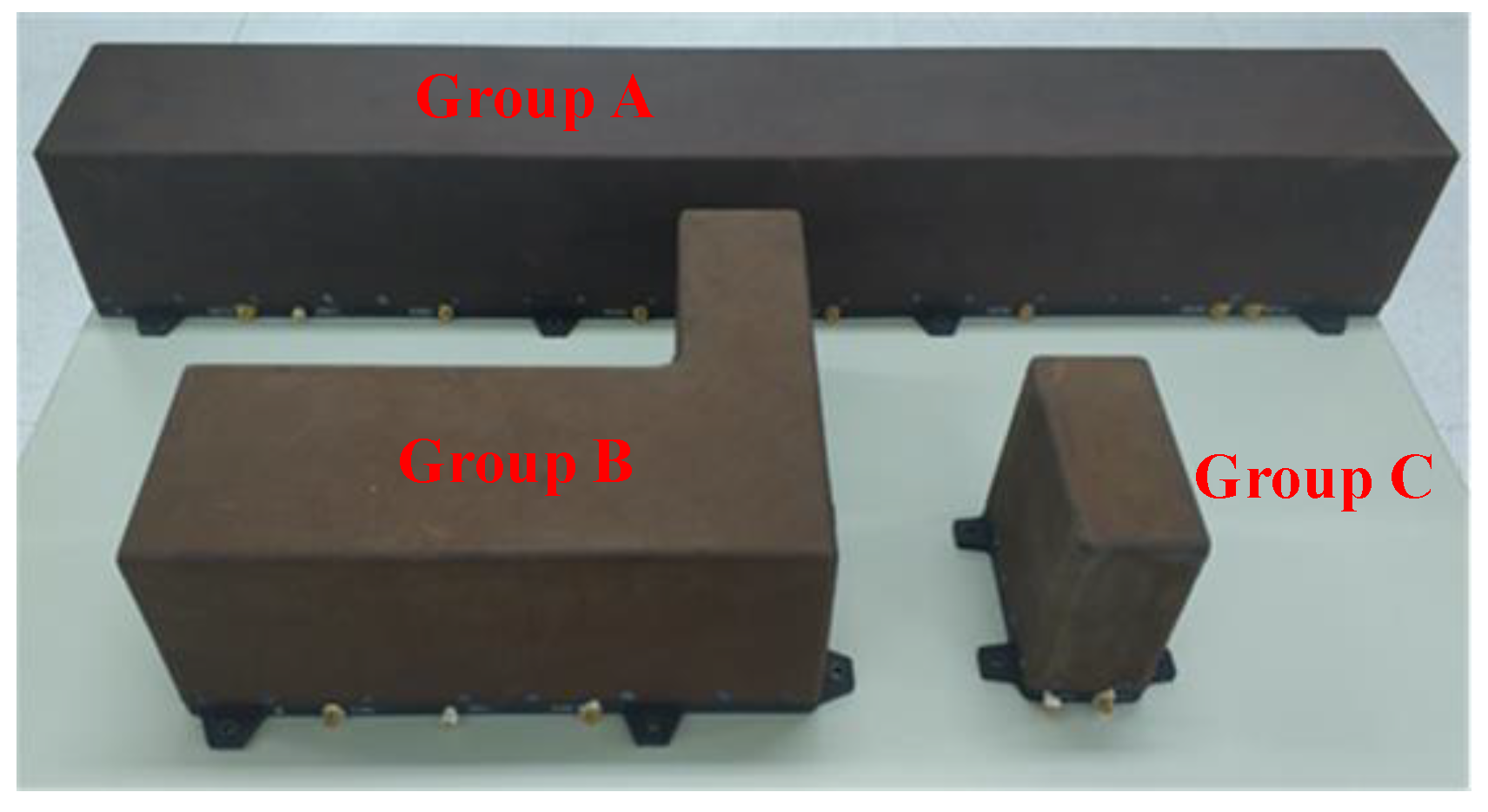
| Volume | Group A: 800 × 120 × 120 mm3 Group B: 300 × 240 × 120 mm3 Group C: 120 × 60 × 120 mm3 |
Publisher’s Note: MDPI stays neutral with regard to jurisdictional claims in published maps and institutional affiliations. |
© 2020 by the authors. Licensee MDPI, Basel, Switzerland. This article is an open access article distributed under the terms and conditions of the Creative Commons Attribution (CC BY) license (http://creativecommons.org/licenses/by/4.0/).
Share and Cite
Lu, W.; Li, Y.; Ji, Y.; Tang, C.; Zhou, B.; Fang, G. Ultra-Wideband MIMO Array for Penetrating Lunar Regolith Structures on the Chang’e-5 Lander. Electronics 2021, 10, 8. https://doi.org/10.3390/electronics10010008
Lu W, Li Y, Ji Y, Tang C, Zhou B, Fang G. Ultra-Wideband MIMO Array for Penetrating Lunar Regolith Structures on the Chang’e-5 Lander. Electronics. 2021; 10(1):8. https://doi.org/10.3390/electronics10010008
Chicago/Turabian StyleLu, Wei, Yuxi Li, Yicai Ji, Chuanjun Tang, Bin Zhou, and Guangyou Fang. 2021. "Ultra-Wideband MIMO Array for Penetrating Lunar Regolith Structures on the Chang’e-5 Lander" Electronics 10, no. 1: 8. https://doi.org/10.3390/electronics10010008
APA StyleLu, W., Li, Y., Ji, Y., Tang, C., Zhou, B., & Fang, G. (2021). Ultra-Wideband MIMO Array for Penetrating Lunar Regolith Structures on the Chang’e-5 Lander. Electronics, 10(1), 8. https://doi.org/10.3390/electronics10010008