Letter

Design and Implementation of LoRa Based IoT Scheme for Indonesian Rural Area

1
Department of Electronic and Computer Engineering (ECE), National Taiwan University of Science and Technology, Taipei City 106, Taiwan
2
Department of Computer Science and Systems Engineering (CSSE), Graduate School of Computer Science and Systems Engineering, Kyushu Institute of Technology, 680-4 Kawazu, Iizuka-shi, Fukuoka 820-8502, Japan
3
Department of Electrical Engineering, University of Jember, Jember 68121, Indonesia
*
Author to whom correspondence should be addressed.
Electronics 2021, 10(1), 77; https://doi.org/10.3390/electronics10010077
Submission received: 31 October 2020 / Revised: 28 December 2020 / Accepted: 29 December 2020 / Published: 4 January 2021
(This article belongs to the Section Industrial Electronics)

Abstract

:
The development of the Internet of Things (IoT) in electronics, computer, robotics, and internet technology is inevitable and has rapidly accelerated more than before as the IoT paradigm is a promising solution in terms of solving real world problems, especially for digitizing and monitoring in real time. Various IoT schemes have successfully been applied to some areas such as smart health and smart agriculture. Since the agriculture areas are getting narrow, the development of IoT in agriculture should be prioritized to enhance crop production. This paper proposes the IoT scheme for long range communication based on Long Range (LoRa) modules applied to smart agriculture. The scheme utilizes the low power modules and long-distance communication for monitoring temperature, humidity, soil moisture, and pH soil. Our IoT design has successfully been applied to agriculture areas which have unstable network connections. The design is analyzed to obtain the maximum coverage using different spreading factors and bandwidths. We show that as the spreading factor increases to 12, the maximum coverage can be transmitted to 1000 m. However, the large coverage also comes with the disadvantages of the increased delays.

1. Introduction

Following the preamble of the Internet of Things (IoT) paradigm, several fields have applied this new paradigm to overcome existing problems. At the beginning of the IoT paradigm, assessment of this technology starts getting popular for addressing communication problems in the medical area. Further, wearable devices for medical applications are developed so that users could conduct a self-health assessment and be monitored automatically. These smart health devices represent a core part of the IoT paradigm. For instance, there is the introduction of the Internet of Things (IoT), as shown in [1,2]. The basic module to create an IoT platform for healthcare, as well as the medical application, is also explained and discussed.
On the other hand, the paradigm of constructing IoT for several fields is also studied, and there are several proposed works discussing the ideas for implementing IoT as the leading player to solve monitoring assessment. One promising field to apply and integrate IoT to the typical traditional system is in agricultural areas. Several applications of IoT in agriculture are offered to end-users [3,4]. In addition, researchers also explore the appropriate technology we may need to construct solutions in agricultural areas by utilizing an IoT scheme [5]. In this paper, Chen et al. provide a cheap and affordable solution illustrated as a full framework named Agritalk. This framework is built by integrating several sensors through the specifically proposed platform committed for agricultural-based applications. For instance, the monitoring scheme to measure soil conditions as well as the current weather is discussed. They also introduced the use of a cloud-based system for the entire IoT solution.
In Indonesia, most farmers are located in rural areas where the communication network is not stable enough for IoT construction [6]. In reality, we need to overcome the availability of network resources. To solve the problem, we proposed the development of an IoT scheme based on Long Range Wide Area (LoRa) communication to send the data to the cloud or remote server. As we know, LoRa is the pioneering of long-range connections with low power consumption and can be one of the solutions for limited resources [7,8].
Therefore, using the LoRa based approach, we can reach long-range communication compared to Bluetooth or other wireless communications [9]. Additionally, not only can it address long distances, but LoRa can also save on power consumption. Comparing to other conventional wire or wireless communications, LoRa is beneficial to be employed in areas with very limited access to the ideal infrastructure. For example, as listed in [8], LoRa has a wide coverage area and supports a private deployment compared to NB-IoT and Sigfox that need licensed spectrum, which may limit the flexibility of the deployment. Furthermore, compared to WiFi, Zigbee, and Bluetooth, LoRa has a relatively low power consumption [8]. Then, several contributions of using our approach can be listed as follows. First, the scheme to implement low power and long-distance communication for the agricultural sector in the Indonesian rural area is designed. Then, we also provide an affordable monitoring solution for Indonesian farmers. Eventually, we conduct an analysis of some factors affecting the performance of LoRa-based communications in a real environment in agricultural fields. The rest of our paper is written as follows. Related work discusses several studies and approaches for IoT solutions implemented in the agricultural sector. After that, the explanation of the proposed scheme is elaborated in design and implementation. Thus, we analyze the experimental results of our study. Finally, future work and the conclusion are stated in the last section.

2. Related Work

As the adoption of IoT in the agriculture field becomes extensive, several challenges have been identified to maximize the privilege of IoT [4]. This challenge includes the necessity of devices for staying active and functioning in a long duration with limited power resources. This low power feature becomes obligatory since the device is located in remote areas where the replacement of the battery is regularly scheduled for long periods due to having large areas to cover, such as large farming areas and vegetable plantations.
One of the solutions to address the challenge is proposed by cellular-IoT technology. The technology is able to cover large areas since the technology maximizes the power of fourth-generation (4G) Long Term Evolution (LTE), which have proven successful commercially and widely used in various applications [10,11]. The examples of cellular-IoT technology applied using licensed LTE are LTE-M and NB-IoT. Both LTE-M and NB-IoT employ Single-Carrier Frequency Division Multiple Access (SC-FDMA) for uplink communication and Orthogonal Frequency Division Multiple Access (OFDMA) for downlink communication. However, the LTE implementation suffers from the energy efficiency problem since it requires high energy consumption to transmit the signal.
Another solution in IoT for agricultural fields is provided by some private service providers such as Sigfox [12] and In-genu [13]. Sigfox is a closed source infrastructure, operating in ISM Sub-GHz and utilizing Differential Binary Phase Shift Keying (DBPSK) for uplink communication and Gaussian Frequency-Shift Keying (GFSK) for downlink communication. Sigfox is mostly famous in Europe, applied in livestock management, smart irrigation, and precision agriculture. Ingenu works under the closed source infrastructure located in San Diego, operating in ISM 2.4 Ghz and utilizing Random Phase Multiple Access (RPMA), which offers a larger bandwidth of 80 MHz. However, private service technology relies on the use of closed source infrastructure, which suffers from a high price in the future.
To respond to these challenges of energy duration and a low-price low-power wide-area network (LPWAN), Long Range Wide Area (LoRa) communication protocol is introduced as the long-range and low power communication, particularly for integrating IoT devices, and is suitable for monitoring the remote and rural areas [14]. LoRa works in a non-licensed band below 1 GHz, which is utilized in long distance communication operations. There are several approaches using LoRa as the machine-to-machine communication system [15]. For example, by constructing LoRa infrastructure, IoT can be implemented in agricultural fields such as for smart agriculture [16,17,18,19] including star-fruit plantations [20], tree farms [21], mushrooms [22], and infrastructure of a rural area specifying to establish a connection with remote horse stable [23], a water irrigation system [24], and application in smart health systems [25,26].
The development of rural areas using IoT approaches inevitably occurs, since IoT is regarded as an appropriate solution in terms of feasibility and reliability in the real world, particularly for digitizing and monitoring surroundings.

3. Design and Implementation

From several points of view, we are going to discuss the design of our framework and platform. Thus, we can explore the model into several parts, such as the design of the general framework for our LoRa infrastructure itself and the deployment of several sensors in LoRa nodes. Moreover, we also look into the details of the algorithm design for data transmission.

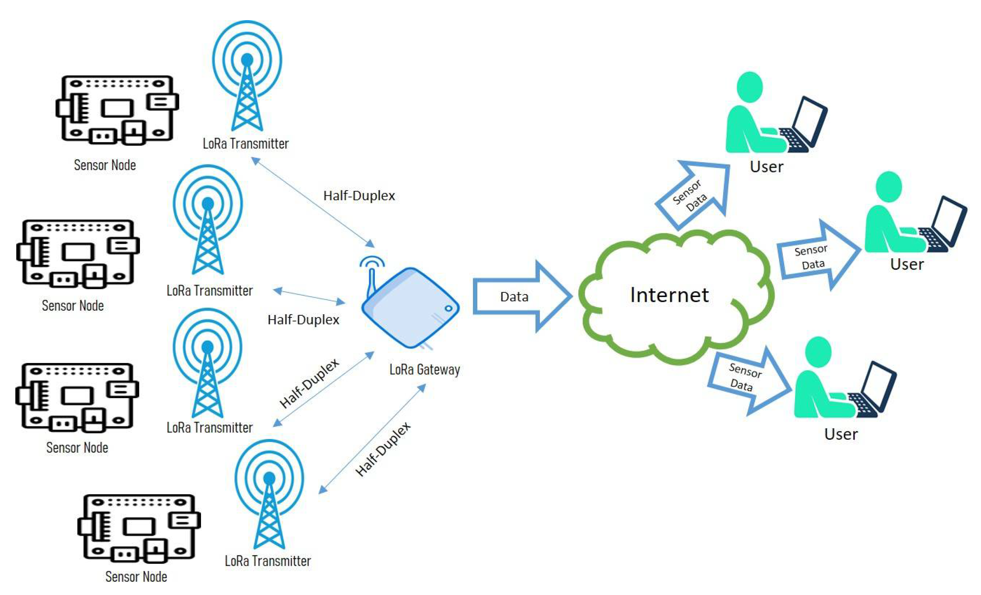
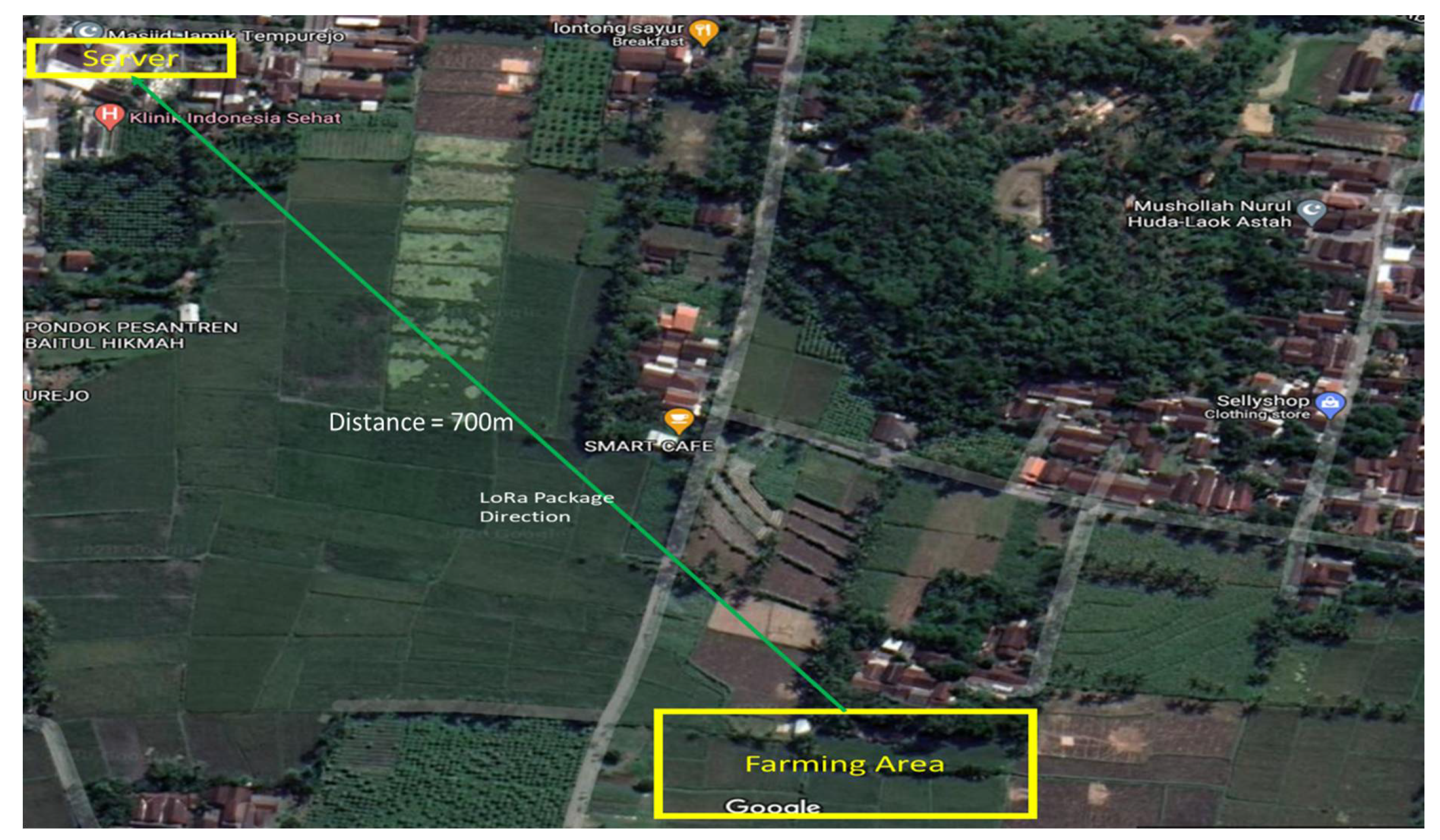
3.1. The Design of LoRa Infrastructure

The design of the Internet of Things (IoT) based on LoRa communications is depicted in Figure 1. The sensor node is equipped by the LoRa transmitter to send the information of sensing measurement. From the sensor node, sensing data is transmitted to the LoRa gateway using half-duplex communication. Therefore, data is acquired by the server, acting as the cloud of our scheme. Eventually, users can monitor the environment of their field and use the record of the data to have an action based on the reality of the field.
Therefore, to have a long-distance capability for transferring the data, we follow the LoRa standard protocol. According to the fundamental formula of LoRa based transferring data scheme, longer distances can be achieved by setting a higher spreading factor, as illustrated in Equation (1). To measure the effectiveness of every parameter, we conduct the experiment to find the best combination we may need.

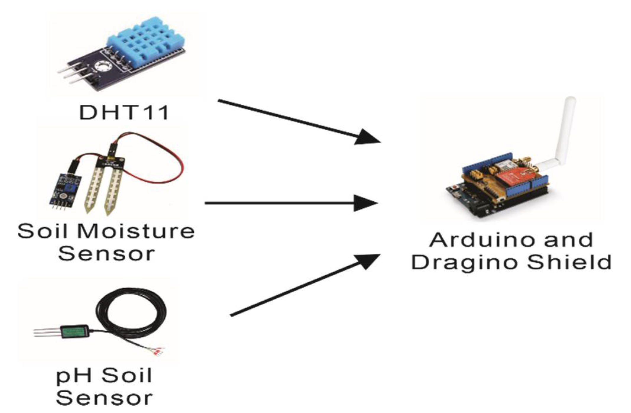
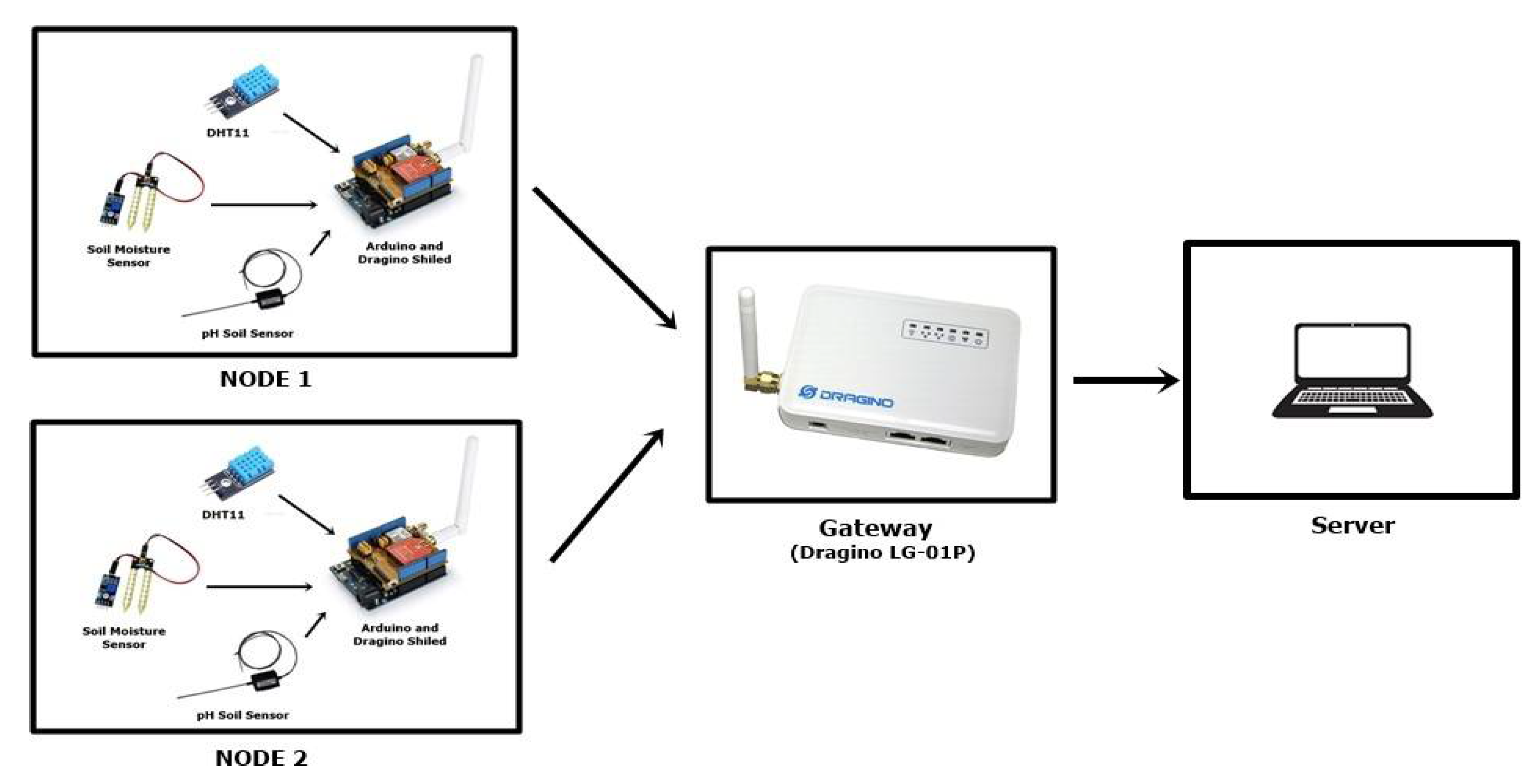
3.2. LoRa Based Dragino Implementation

The pilot experiment utilizes the Dragino Lora IoT Kit [27] as a Lora framework with a frequency of 925 Mhz, a maximum link budget around 168 dB, and a dynamic range RSSI around 127 dB. The setup of the Lora system requires two devices, which are located separately. The first device called as a client, which is located in a remote area, consists of a LoRa shield and Arduino Uno. The client, in which refer to edge computing paradigm, is surrounded and connected to several sensors such as a DHT11 [28] for air temperature and humidity, a soil moisture sensor for estimation of water content in soil, and a pH soil sensor for measuring soil pH. The client works by collecting data obtained from three different sensors, then broadcasting them via LoRa wireless. The detail of client architecture is shown in Figure 2.
Thus, to store the recorded data, we construct a client-server communication using Dragino LG-01P LoRa gateway. The server receives and collects the data which is broadcasted by several clients. Figure 3 shows the server architecture. The server then maps the data received from clients by adding one dummy variable such as code “01” for NODE 1 and “02” for NODE 2. The Arduino IDE is installed to the server so that the users can access the data and data logger.

3.3. The LoRa Physical Layer

LoRa uses frequency chirp modulation with varying frequency over time to decode information. This is known as chirp spectrum modulation. Due to the linearity property of the chirp, the frequency offset in the server and client are equivalent, eliminated by the decoder. This advantage property allows the frequency offset, reaching 20% of the bandwidth without impacting the decoding process [29]. In this LoRa modulation scheme, several parameters are open to customization. These parameters include bandwidth (BW), the spreading factor (SF), and code rate (CR). LoRa uses the logarithm in base 2 for chirp in the spreading factor. It influences the bitrate modulation, resistance to noise, and decoding easily. In this type modulation, the chirp rate will depend on the bandwidth parameter, as the chirp rate is proportional to the bandwidth. Equation (1) formulates the relation between the chirp rate and the bandwidth.
T s =   2 S F B W
where Ts represents the duration of package transmission, SF is the spreading factor, and BW is the bandwidth. This formula represents that the increasing spreading factor will eventually divide the span of the frequency of chirp by 2 and multiply the duration of package transmission. Moreover, the bit rate at any given spreading factor is proportional to the bandwidth, also doubling the transmission rate. Moreover, the code rate (CR) is also open to adjustment. Equation (2) formulates the customizable CR in LoRa modulation.
R b = S F   ×     B W 2 S F   ×   C R
where Rb is the bit rate. The Equation (2) allows us to compute the bit rate (Rb) in LoRa modulation.

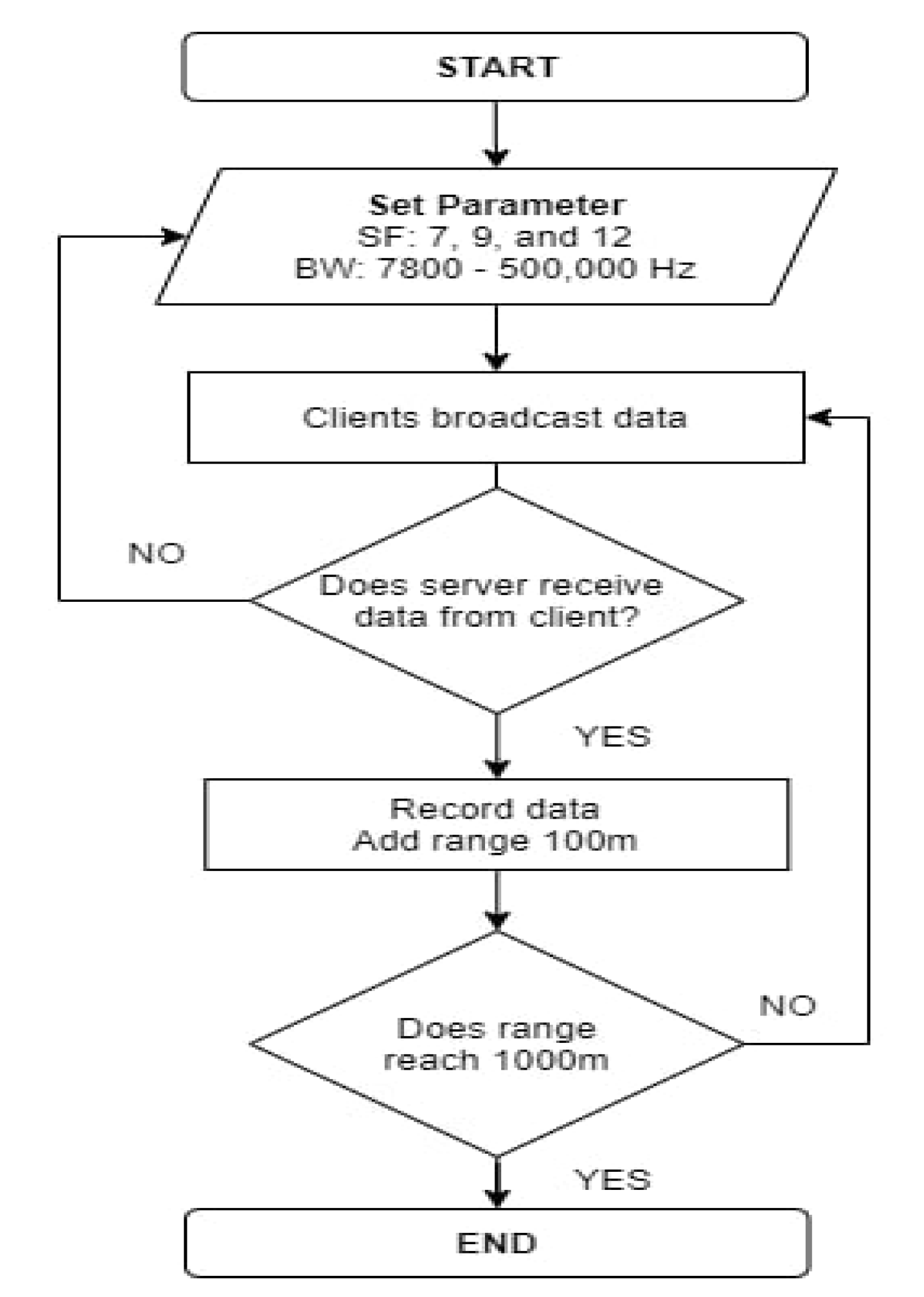
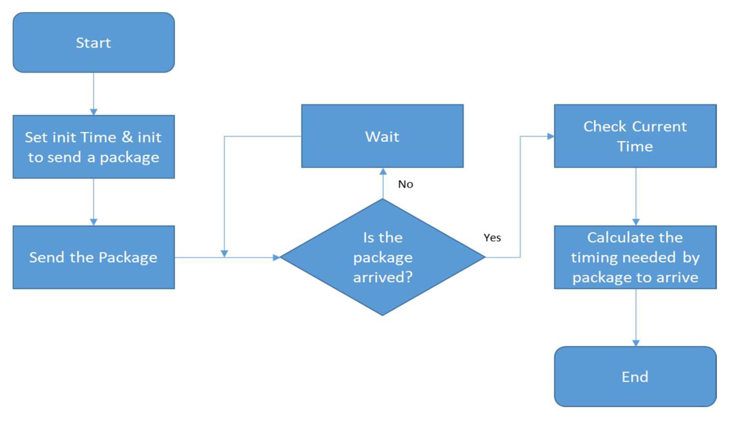
3.4. Testing Scenario

In this scenario, we verify that the maximum distance and packet delay of the LoRa-based Dragino implementation in agriculture can be reached. The test is conducted by varying the spreading factor and the bandwidth. First, the spreading factor is varied from 7, 9, and 12. Moreover, the bandwidth is set in values of the range of 7800–500,000 Hz. The delay as well as the maximum data are measured to have an insight into the data communication from the client side to the server. The location of clients is spread out in the range of 50–1000 m with an increment of 100 m. Figure 4 shows the test flowchart of LoRa-based Dragino implementation. For the delay test, we take the average value of the delay at each location that is passed for 1 min. The delay measurement was implemented in the Microcontroller used by device nodes. The scheme for calculation is depicted in Figure 5. Please note that the spreading factor is set firstly, then followed by the bandwidth value. This is required to identify the sufficient bandwidth value so that the data is transmitted at the closest distance to the server.

4. Result and Discussion

We had established and set the real environment of the LoRa-based Dragino implementation in rural areas, more specifically, on one of authors’ farming areas, as illustrated in Figure 6. The surroundings of the farming site used to conduct the experiment is depicted in Figure 7. The map was taken from Google Maps, and the implementation was located in Tempurejo village, Jember, Indonesia. We also conducted assessments for evaluating the performance of the default parameter from Dragino and measuring available variables affecting LoRa performance, such as spreading factors and bandwidth. Gateway was located near the server, and the distance between the gateway and the farming site was around 700 m. We adjusted the distance of measurement between device nodes and gateway based on the straight line shown in Figure 7 and used in the architecture of the communication protocol as shown in Figure 3.

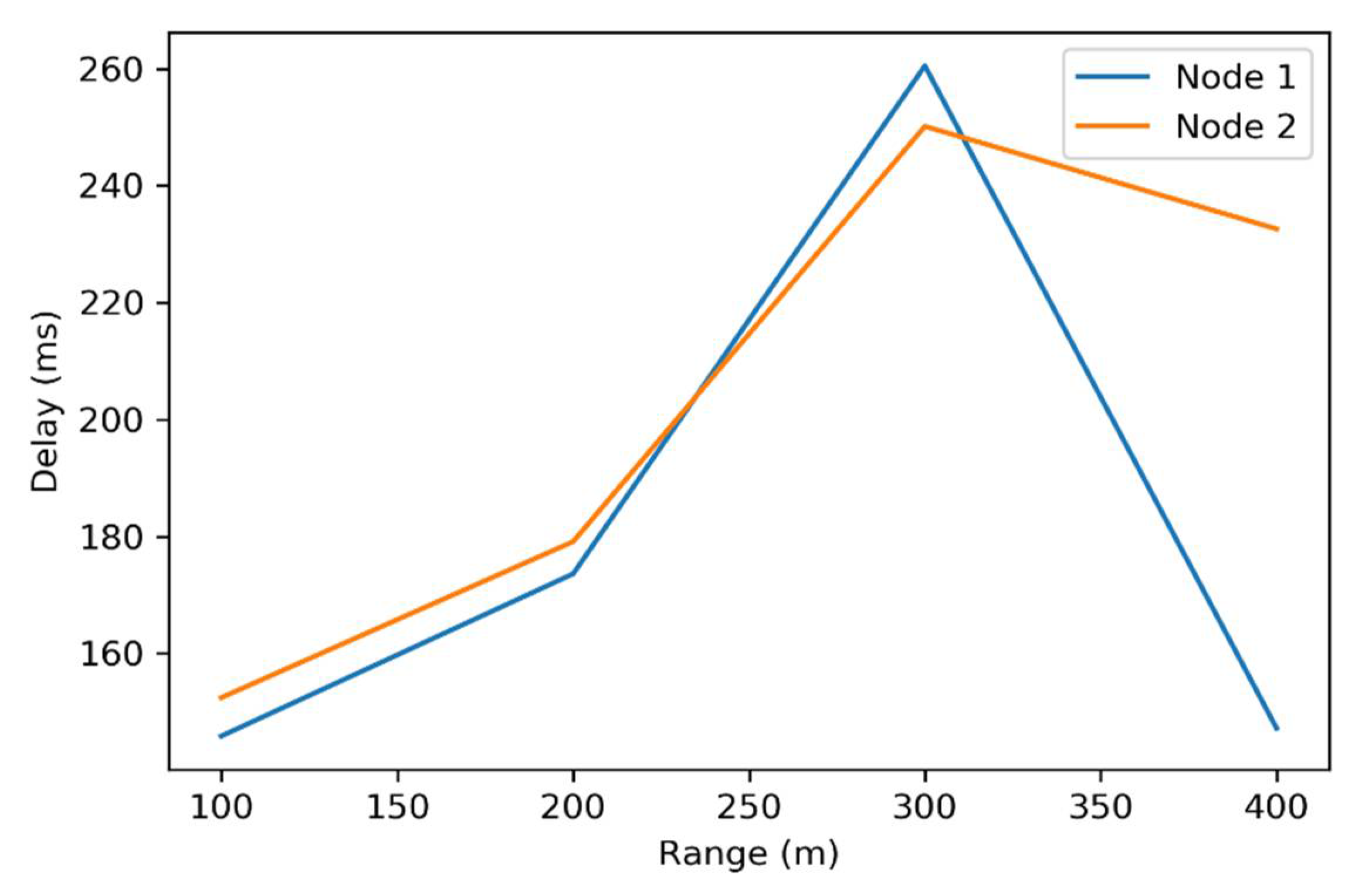
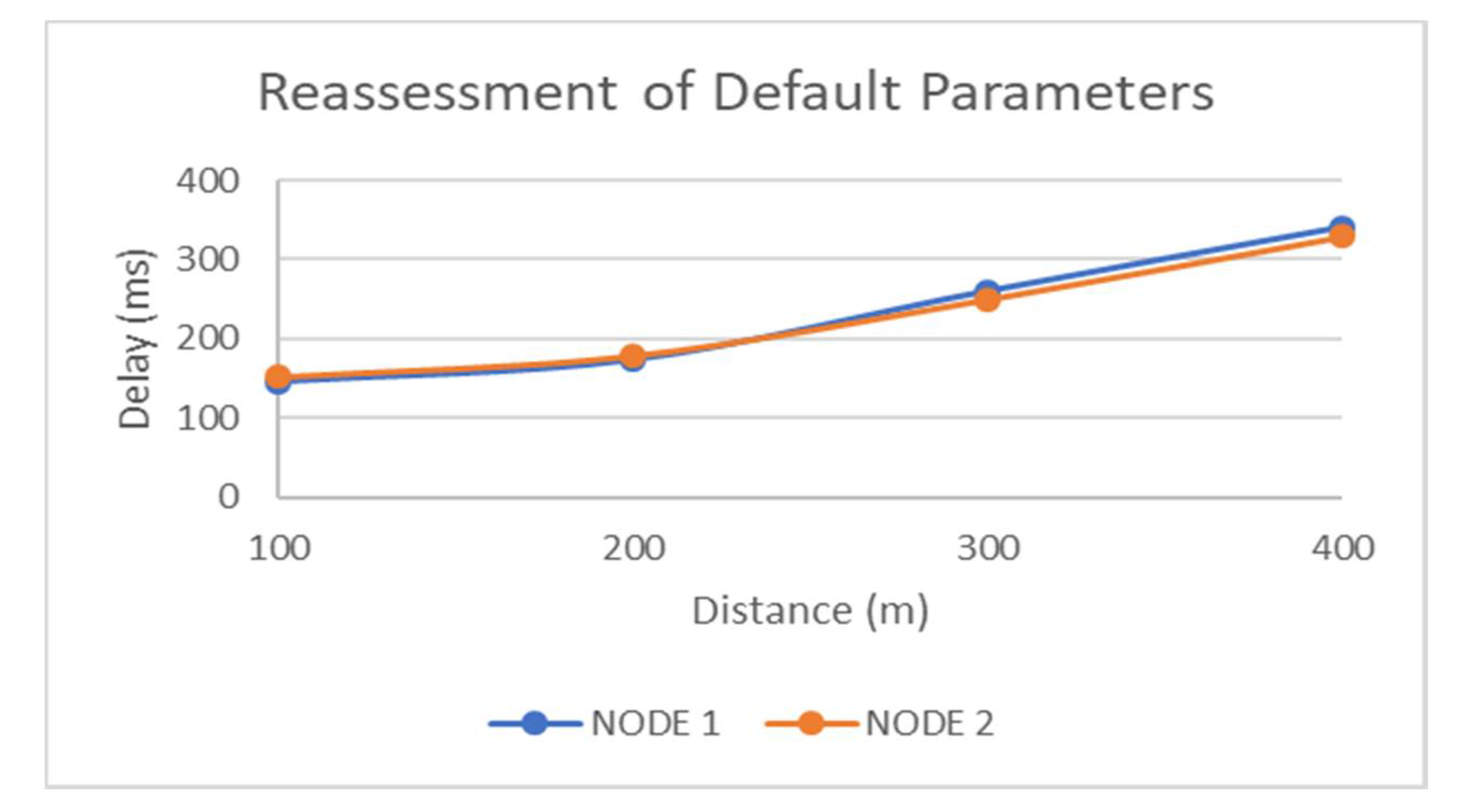
4.1. Analysis Using Default Parameter

Firstly, the test was conducted to assess the default parameters from Dragino comprising the spreading factor of 7 and the bandwidth of 125 kHz. The parameter was carried out following the existing scenario explained in Section 3. Table 1 and Figure 8 show the detailed result of the experiment. As can be seen in Table 1, the average delay of the proposed scheme was around 145–260 ms. The experiment to get the real behavior of the available default parameters from Dragino was set to get the real data from a distance of 100 m to 400 m as a maximum distance. We also noticed that, the further the distance between the server and the client, the delay may increase, indicated by the data taken in the range between 100 to 300 m. However, an anomaly came in the data received from range 400 m. We further investigated that it may come from the shaking device caused by natural effects, such as wind or an animal passing through our device nodes in a real environment. This phenomenon, experiencing of the shaking device, may also affect the wiring connection, and then the LoRa module cannot smoothly process the data sending. A further experiment is necessary to support our findings.

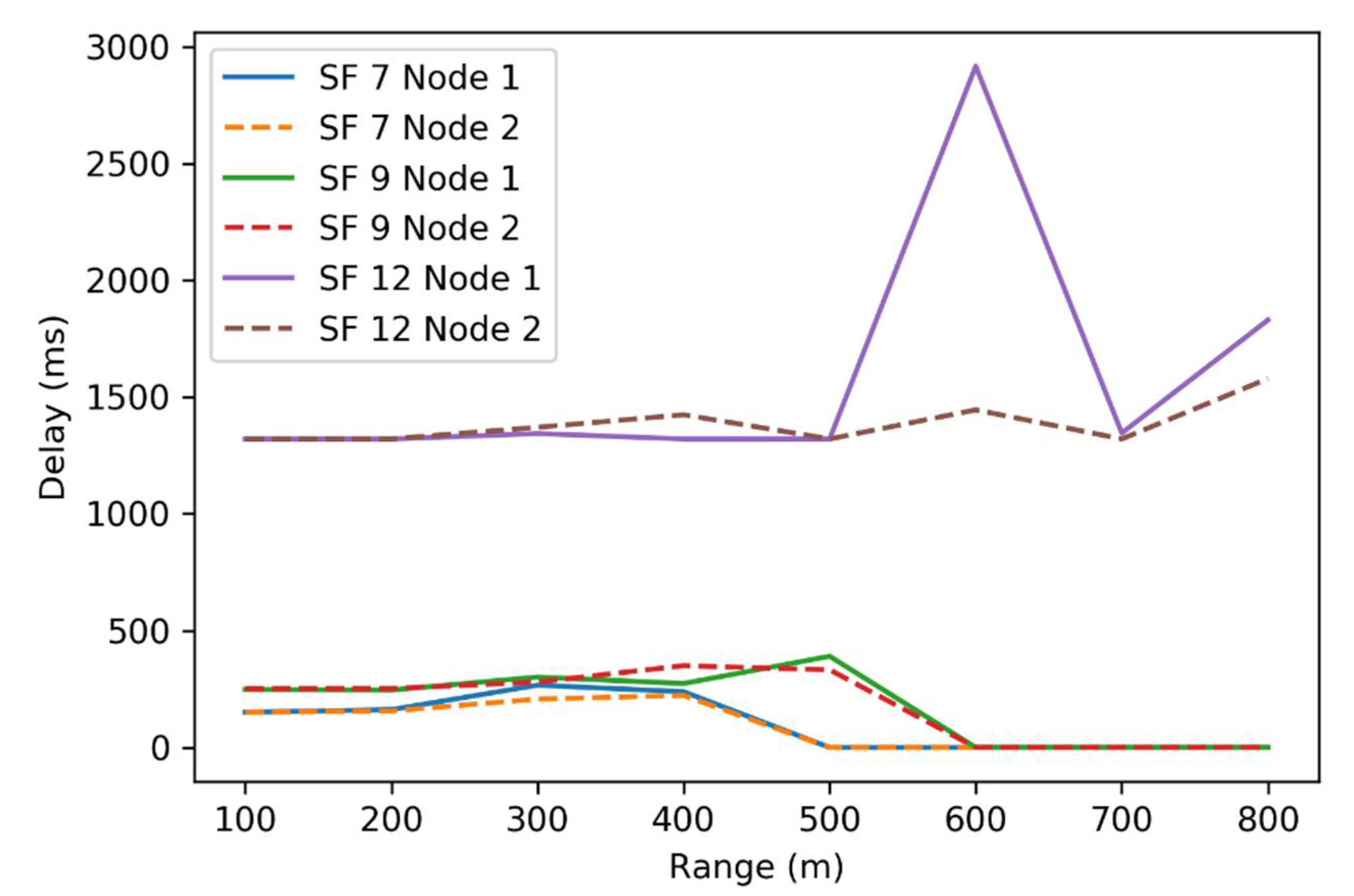
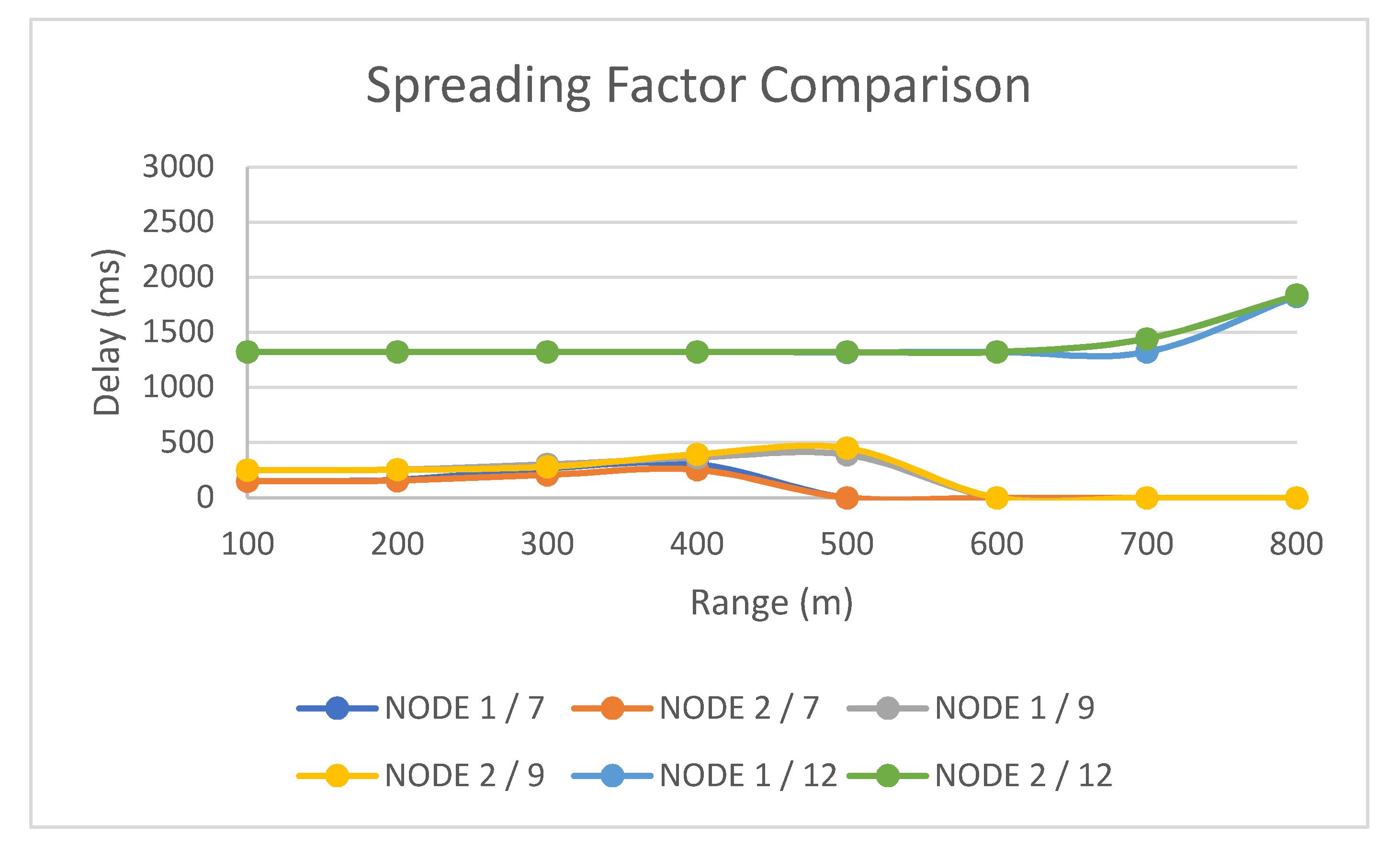
4.2. Analysis in Varied Parameters

Secondly, we conducted the experiment using the varied parameter as explained in Section 3. The bandwidth parameter was varied according to Figure 4. The experimental objective was to find the appropriate parameters which may perform well during package communications in our real environment. Theoretically, with the increase of spreading factor (SF), the maximum bandwidth that can be set will be reduced. As per the preliminary investigation, we found some anomalies that may affect the implementation in the real world. Then, to find the maximum bandwidth setting for specific SF in our implementation, we tried the bandwidth value ranging from 7800 Hz to 500,000 Hz. Table 2 shows the specific parameter of the spreading factor and the maximum bandwidth that can be used and is workable in our case. The value of SF was selected based on the fact that the default value of SF in Dragino is 7. Therefore, to find the longest distance of the module we used, we need to have the increasing value. Then, 9 was chosen as the median value, since 12 is the maximum workable value supported by the module. Eventually, the findings were regarded as the main consideration to adjust and set the parameters on a second experiment to have the workable solution for our specific agricultural use.

4.3. Coverage Performance Analysis

To measure the package communication in a certain coverage, we evaluated the employed module performance during sending and receiving of the package. The evaluation was conducted to assess the network performance of the LoRa communication scheme ranging from 100 m to 1000 m using the parameters assessed in the previous experiment. Table 3 and Figure 9 depict the performance of the LoRa communication scheme implemented in our work. It shows that some spreading factors have reached the maximum range early, for instance the spreading factor of 7 reached 400 m and the spreading factor of 9 reached 500 m, respectively. This was indicated by 0 transmittal received in the servers. Besides, we also noticed that the varied spreading factor eventually influences the delay. As the spreading factor increases, the delay of communication between the client and the servers was slightly to have a longer communication shown by the increasing of delay, for instance the spreading factor of 7 suffers a 150 ms delay, while the spreading factor of 12 suffers an almost 10 times longer delay. However, the spreading factor also affected the range of the communication between the server and the client. The higher the spreading factor value was given, the further the distance that could be reached, so that the devices could communicate with each other in a longer range. Meanwhile, by increasing the spreading factor, it was affecting the delay generated by the system. The delay took a longer time even if the transmission was conducted in low range. For example, for spreading factor 7, an average delay of the proposed scheme was 150 ms, but on spreading factor 9, the average of the delay value increased to 250 ms. Likewise, as the spreading factor changed to 12, the delay increased to 1320 ms.
Besides that, by looking at the facts contained in Table 3, several findings could be summarized. First, to be able to transmit data at a close range, the spreading factor parameters need to be decreased. Meanwhile, if the user prefers to transmit data over long distances, the value of the spreading factor must be increased. Second, adjusting the value of the spreading factor to receive data transmission with a specific range is significantly affecting the delay generated by the system. Thus, the further the data is transmitted, the spreading factor value needs to be increased. Assessing the value of the spreading factor, it is clearly presented in Table 3 that adjustment of the spreading factor to the higher value was impacting the delay communication in the proposed work, even at very close distances (100 m). Meanwhile, the clear illustration of the relationship between the value of the spreading factor to the distance and delay is depicted in Figure 9. From the graph shown in Figure 9, it could be notably seen that the delay measured in our real implementation was assessed to have the rising trend indicated by the increasing of the time measured during the data transmission. However, the anomaly was found in the data taking from NODE 1. As can be seen in Table 3, NODE 1 experienced the data deviation for the communication taken from the distance of 600 m. We found that the nature effects played an essential role for the deployment of LoRa in agriculture. The experience of the device shaking, caused by nature such as wind or rain, would have an impact for the communication in the real world. We also conducted the experiment for 900 m and 1000 m. However, in our proposed work implementation, the device node could not reach the gateway.

4.4. Reassessment of the Package Transfer

The reassessment of the data transfer was conducted three times, and the goal was to measure the real delay of the LoRa communication implemented in our proposed work. A careful experiment was conducted by ensuring the area was clear enough from animals passing by our devices. To make the circuit connection more robust, we also carefully shielded the wiring connection. Therefore, the experience of shaking the device could be minimized as well. In addition, the data presented in this section is the average value of all experiments (three times). As depicted in Table 4 and Figure 10, the data clearly presents that the anomaly shown in Table 1 was not occurring. The data taken from a clear environment was consistent without experiencing an anomaly.
The reassessment of the data transfer in a possibly clear environment was also performed to investigate the several spreading factors used in the proposed work. Using a shielded connection and a relatively clear environment, the error presented in Table 3 could be avoided, as shown in Table 5 and depicted in Figure 11. Therefore, as we face the real effect from animals or even nature, a careful design is needed to ensure the robustness of the scheme and to minimize errors.

5. Conclusions

We propose an IoT scheme for monitoring in the agriculture area. Therefore, the implementation of the IoT scheme for long range communication is constructed and the LoRa-based dragino scheme in agricultural areas is feasibly effective to be adopted in order to monitor the areas within long distances. Thus, several experiments for data transfer have been conducted to test the performance of our proposed design. Some factors might affect the performance of LoRa-based communications in a real environment. Eventually, the reassessments of data transfer in a clear environment are re-conducted to check the anomaly in the previous experiments. In addition, by reassessing our platform in a clear environment, it is confirmed that the anomaly data can be avoided. Therefore, the LoRa developers should be careful enough to construct and assess the effective parameters and nature consideration used for realizing the LoRa scheme implemented in remote or rural areas.

Author Contributions

Conceptualization, S.W.P., M.K., and J.-S.L.; data curation, C.A.; formal analysis, S.W.P.; investigation, Y.A.; resources, S.W.P. and J.-S.L.; supervision, M.K. and J.-S.L.; visualization, Y.A.; writing—original draft, S.W.P. and M.F.; writing—review and editing, M.F.; Experimental field (farming area), S.W.P. All authors read and agreed to the published version of the manuscript.

Funding

The authors gratefully acknowledge the support by the Kyushu Institute of Technology—National Taiwan University of Science and Technology Joint Research Program, under Grant Kyutech-NTUST-108-04

Informed Consent Statement

Not Applicable.

Data Availability Statement

Data sharing not applicable. No new data were created in this study.

Acknowledgments

This study was supported by a collaborative research project between the Kyushu Institute of Technology (Kyutech) and the National Taiwan University of Science and Technology (Taiwan-Tech).

Conflicts of Interest

The authors declare that they have no known competing financial interests or personal relationships that could have appeared to influence the work reported in this paper.

References

  1. Wu, F.; Wu, T.; Yuce, M. An Internet-of-Things (IoT) Network System for Connected Safety and Health Monitoring Applications. Sensors 2018, 19, 21. [Google Scholar] [CrossRef] [PubMed] [Green Version]
  2. Baker, S.; Xiang, W.; Atkinson, I. Internet of Things for Smart Healthcare: Technologies, Challenges, and Opportunities. IEEE Access 2017, 5, 26521–26544. [Google Scholar] [CrossRef]
  3. Haxhibeqiri, J.; Poorter, E.D.; Moerman, I.; Hoebeke, J. A Survey of LoRaWAN for IoT: From Technology to Application. Sensors 2018, 18, 3995. [Google Scholar] [CrossRef] [PubMed] [Green Version]
  4. Tzounis, A.; Katsoulas, N.; Bartzanas, T.; Kittas, C. Internet of Things in agriculture, recent advances and future challenges. Biosyst. Eng. 2017, 164, 31–48. [Google Scholar] [CrossRef]
  5. Chen, W.; Lin, Y.; Lin, Y.; Chen, R.; Liao, J.; Ng, F.; Chan, Y.; Liu, Y.; Wang, C.; Chiu, C.; et al. AgriTalk: IoT for Precision Soil Farming of Turmeric Cultivation. IEEE Internet Things J. 2019, 6, 5209–5223. [Google Scholar] [CrossRef]
  6. Kusumawati, D. The Potential Adoption of the Internet of Things in Rural Areas. In Proceedings of the 2018 International Conference on ICT for Rural Development (IC-ICTRuDev), Badung Regency, Indonesia, 17–18 October 2018. [Google Scholar]
  7. Adelantado, F.; Vilajosana, X.; Tuset-Peiro, P.; Martinez, B.; Melia-Segui, J.; Watteyne, T. Understanding the Limits of LoRaWAN. IEEE Commun. Mag. 2017, 55, 34–40. [Google Scholar] [CrossRef] [Green Version]
  8. Ertürk, M.A.; Aydın, M.A.; Büyükakkaşlar, M.T.; Evirgen, H. A Survey on LoRaWAN Architecture, Protocol and Technologies. Future Internet 2019, 11, 216. [Google Scholar] [CrossRef] [Green Version]
  9. Bor, M.C.; Roedig, U.; Voigt, T.; Alonso, J.M. Do LoRa Low-Power Wide-Area Networks Scale? In Proceedings of the 19th ACM International Conference on Modeling, Analysis and Simulation of Wireless and Mobile Systems, Malta, 13–17 November 2016. [Google Scholar]
  10. Lee, J.; Kim, Y.; Kwak, Y.; Zhang, J.; Papasakellariou, A.; Novlan, T.; Sun, C.; Li, Y. LTE-advanced in 3GPP Rel -13/14: An evolution toward 5G. IEEE Commun. Mag. 2016, 54, 36–42. [Google Scholar] [CrossRef]
  11. Mezzavilla, M.; Zhang, M.; Polese, M.; Ford, R.; Dutta, S.; Rangan, S.; Zorzi, M. End-to-End Simulation of 5G mmWave Networks. IEEE Commun. Surv. Tutor. 2018, 20, 2237–2263. [Google Scholar] [CrossRef]
  12. Zuniga, J.; Ponsard, B. Sigfox System Description. Available online: https://www.ietf.org/proceedings/97/slides/slides-97-lpwan-25-sigfox-system-description-00.pdf (accessed on 27 June 2020).
  13. Ingenu. How RPMA Works. Available online: https://www.ingenu.com/portfolio/how-rpma-works-the-making-of-rpma/ (accessed on 27 June 2020).
  14. Bouras, C.; Kokkinos, V.; Papachristos, N. Performance evaluation of LoraWan physical layer integration on IoT devices. In Proceedings of the 2018 Global Information Infrastructure and Networking Symposium (GIIS), Thessaloniki, Greece, 23–25 October 2018. [Google Scholar]
  15. Sundaram, J.P.S.; Du, W.; Zhao, Z. A Survey on LoRa Networking: Research Problems, Current Solutions, and Open Issues. IEEE Commun. Surv. Tutor. 2020, 22, 371–388. [Google Scholar] [CrossRef] [Green Version]
  16. Semtech. Revolutionising Smart Agriculture Using Semtech’s LoRa Technology. Available online: www.semtech.com/uploads/technology/LoRa/WP-SEMTECH-LORA-SMART-AGRICULTURE.pdf (accessed on 28 June 2020).
  17. Citoni, B.; Fioranelli, F.; Imran, M.A.; Abbasi, Q.H. Internet of Things and LoRaWAN-Enabled Future Smart Farming. IEEE Internet Things Mag. 2019, 2, 14–19. [Google Scholar] [CrossRef]
  18. Germani, L.; Mecarelli, V.; Baruffa, G.; Rugini, L.; Frescura, F. An IoT Architecture for Continuous Livestock Monitoring Using LoRa LPWAN. Electronics 2019, 8, 1435. [Google Scholar] [CrossRef] [Green Version]
  19. Hardie, M.; Hoyle, D. Underground Wireless Data Transmission Using 433-MHz LoRa for Agriculture. Sensors 2019, 19, 4232. [Google Scholar] [CrossRef] [PubMed] [Green Version]
  20. Rachmani, A.F.; Zulkifli, F.Y. Design of IoT Monitoring System Based on LoRa Technology for Starfruit Plantation. In Proceedings of the TENCON 2018—2018 IEEE Region 10 Conference, Korea, Korea, 28–31 October 2018. [Google Scholar]
  21. Yim, D.; Chung, J.; Cho, Y.; Song, H.; Jin, D.; Kim, S.; Ko, S.; Smith, A.; Riegsecker, A. An experimental LoRa performance evaluation in tree farm. In Proceedings of the 2018 IEEE Sensors Applications Symposium (SAS), Seoul, Korea, 12–14 March 2018. [Google Scholar]
  22. Ibrahim, N.H.N.; Brahim, A.R.; Mat, I.; Harun, A.N.; Witjaksono, G. IR 4.0 using IoT and LORAWAN to Accelerate Lentinula Edodes Growth. In Proceedings of the 2018 2nd International Conference on Smart Sensors and Application (ICSSA), Kuching, Malaysia, 24–26 July 2018. [Google Scholar]
  23. Grunwald, A.; Schaarschmidt, M.; Westerkamp, C. LoRaWAN in a rural context: Use cases and opportunities for agricultural businesses. In Proceedings of the Mobile Communication-Technologies and Applications; 24. ITG-Symposium, Osnabrueck, Germany, 15–16 May 2019; pp. 1–6. [Google Scholar]
  24. Glória, A.; Dionisio, C.; Simões, G.; Cardoso, J.; Sebastião, P. Water Management for Sustainable Irrigation Systems Using Internet-of-Things. Sensors 2020, 20, 1402. [Google Scholar] [CrossRef] [PubMed] [Green Version]
  25. Olatinwo, D.; Abu-Mahfouz, A.; Hancke, G. A Survey on LPWAN Technologies in WBAN for Remote Health-Care Monitoring. Sensors 2019, 19, 5268. [Google Scholar] [CrossRef] [PubMed] [Green Version]
  26. Yang, G.; Liang, H. A Smart Wireless Paging Sensor Network for Elderly Care Application Using LoRaWAN. IEEE Sens. J. 2018, 18, 9441–9448. [Google Scholar] [CrossRef]
  27. Dragino Lora IoT Kit. Available online: https://www.dragino.com/ (accessed on 11 November 2020).
  28. DHT11 Datasheet. Available online: https://www.mouser.com/datasheet/2/758/DHT11-Technical-Data-Sheet-Translated-Version-1143054.pdf (accessed on 11 November 2020).
  29. Semtech SX1276. Available online: https://www.semtech.com/products/wireless-rf/lora-transceivers/sx1276 (accessed on 27 June 2020).
Figure 1. Internet of Things (IoT) based on Long Range Wide Area (LoRa) communications.
Electronics 10 00077 g001
Figure 2. Client architecture.
Electronics 10 00077 g002
Figure 3. Client–server communication flow.
Electronics 10 00077 g003
Figure 4. Testing scenario flowchart.
Electronics 10 00077 g004
Figure 5. Delay measurement scheme.
Electronics 10 00077 g005
Figure 6. Delay measurement scheme.
Electronics 10 00077 g006
Figure 7. The surroundings of the farming site.
Electronics 10 00077 g007
Figure 8. Delay graph from default parameters.
Electronics 10 00077 g008
Figure 9. Comparison of delay graph from changing parameters of spreading factor.
Electronics 10 00077 g009
Figure 10. Reassessment of default parameters.
Electronics 10 00077 g010
Figure 11. The delay graph from the reassessment of several spreading factors.
Electronics 10 00077 g011
Table 1. The result with default parameters.
Range (m)Time (ms)
Node 1Node 2
100145.8934152.4674
200173.6295179.138
300260.4892250.1508
400147.229232.6086
Table 2. Spreading factors and maximum workable bandwidth settings.
Spreading FactorMaximum Workable Bandwidth Settings
7125 KHz
931,250 Hz
12125 KHz
Table 3. Assessment of several spreading factor parameters.
Range (M)Time (ms)
Node 1/7Node 2/7Node 1/9Node 2/9Node 1/12Node 2/12
100150.9788054151.3590426248.4338139251.709302313211320.982456
200162.0192308156.5565111245.9020101252.490018113211321
300266.8132678207.2474747301.3913934280.07221011344.1754391370.830189
400238.8282828222.8467153273.9149338350.15083813211424.627451
50000390.5179856332.60857141320.9848481321
60000002917.2083331445.622642
70000001346.4230771321
80000001830.3191491579.456522
Table 4. The average value from reassessment of default parameters.
Range (m)Time (ms)
Node 1Node 2
100145.8934152.4674
200173.6295179.138
300260.4892250.1508
400341.2726329.2309
Table 5. The average value from the reassessment of several spreading factor parameters.
Range (M)Time (ms)
Node 1/7Node 2/7Node 1/9Node 2/9Node 1/12Node 2/12
100150.978805151.359042248.433813251.70930213211321
200162.019231156.556511254.902010252.49001813211321
300266.813268207.247475301.391393280.07221013211321
400305.465116252.846715363.876872391.51612913211322
50000390.517985449.64042513201321
600000013211321
70000001321.0008071440.981308
80000001827.9631581837.191083
Publisher’s Note: MDPI stays neutral with regard to jurisdictional claims in published maps and institutional affiliations.

