1. Introduction
Remote operation and automation of mining systems are priority industry-wide goals in achieving improvements in safety and productivity. This means accurate sensing of equipment position in an underground mine is a fundamental requirement to replace human observation. A potential solution to this problem is the use of laser scanning (LIDAR), which is currently one of the most widely used technologies worldwide for measurement of position in automation of mobile equipment [
1,
2,
3]. It offers rapid, accurate, and flexible capture of real-world spatial data and is ideally suited for underground mining operations where it has been used for mapping and navigation in hard rock mining for a number of years, [
4,
5]. Hard rock mining equipment, however, does not require any consideration of safety in explosive atmospheres and continues to be an active research field [
6,
7,
8].
However, the uptake of LIDAR-based sensing in underground coal mining, typically called longwall mining, has been limited due to a range of practical operational challenges. Major impediments include the lack of suitable equipment enclosures to enable the operation of proven commercial LIDAR systems in the explosion risk environments that exist to some degree in all underground coal mines. Installation options are limited due to sensing equipment size as well and mounting requirements to sustain reliable scanning performance. Finally, the maintenance burden involved in meeting ongoing regulatory compliance requirements is high [
9,
10,
11].
In response to these challenges, CSIRO Australia has developed a new laser scanning and imaging system specifically designed for use in explosion risk zones [
12,
13,
14]. Called ExScan
®, this system offers an integrated sensing platform that can be readily deployed in multiple applications to meet user needs including remote and automated mining applications. The technology can be integrated with existing automation systems or used as a standalone sensing and scanning solution.
2. Background
In industries that deal with hazardous dust or gases, there is an ever-present explosion risk. These areas are known as explosion risk zones (ERZs) or ATEX zones [
9]. To operate electrical equipment in these areas, high standards of design, installation, and maintenance are required to ensure that risk presented by the presence of these devices is minimised to an acceptable level [
10].
There are several protection techniques that can be used (
Table 1), and rigorous standard and certification processes exist that must be followed before installation of this equipment underground is permitted by regulatory authorities.
For each of these techniques, there are limitations and requirements to ensure that the equipment being installed in the environment cannot propagate any internal spark or explosion to the surrounding explosive area. Enclosures are also required to provide protection for installed equipment from the harsh environmental conditions experienced underground. For instrumentation equipment, two kinds of protection listed in
Table 1 are often considered.
Intrinsically safe (IS) protection means that equipment must be designed so there is insufficient stored electrical energy in any of the components in the device to cause a spark capable of igniting a flammable atmosphere in which the equipment is operating when energy is released either during operation or due to fault or damage situations. This implies the use of very low operating voltages and currents and no significant energy storage within the system. Only an ingress protection (IP)-rated enclosure is required for this equipment. However, most technologies of practical value for environmental sensing cannot fall within these constraints, and hence the need for added protection such as a flameproof enclosure, which can safely contain equipment with significant energy storage.
Flameproof enclosures are designed on the assumption that no exclusion mechanism will completely stop gas from an explosive atmosphere penetrating the enclosure and coming in contact with equipment in it. Therefore, if the device inside the enclosure generates a spark or a high enough temperature, an explosion will occur if an explosive atmosphere is present. However, the explosion is contained within the enclosure, and flame propagation to the surrounding atmosphere is prevented. This is achieved by designing the enclosure to have a mechanical strength suitably greater than the pressure generated by an explosion of gas in the internal volume so that it does not rupture. Additionally, a flame path is designed into the enclosure to emit the flue gases through a route that ensures cooling to a point where there is no ability to trigger a further explosion in the outside atmosphere.
To address the protection issues while allowing new other-industry sensors and technology installation to drive remote operation and control in mining, CSIRO has undertaken a research project funded by the Australian Coal Association Research Program (ACARP) to develop a widely available enclosure for various sensors, with a three-dimensional scanning LIDAR as the initial application. This paper describes the process and outcomes of this project.
3. Key Design Requirements
The following are the key factors that drove the current flameproof enclosure design:
Low cost: The design must be economically practical in order to allow ready use of existing imaging solutions.
Field-of-view: To make best use of imaging systems and best access to imaging the underground environment, the viewport must be as large as possible. Accuracy of the LIDAR measurements though the transparent dome should be fundamentally equivalent to the performance of the base sensor (+/−30 mm).
Regulatory compliance: The enclosure must achieve IEC 60079-0,1 Ex db certification: There can be no compromise in the factors relevant to achieving flameproof enclosure standards compliance.
3.1. Design for Minimum Cost
Due to the need to achieve higher mechanical strength and to allow for the costs of testing for certification requirements, flameproof enclosures will not be comparable in cost to enclosures which provide only environmental (IP) protection. While certification costs are unavoidable, there are opportunities to explore low-cost manufacture to achieve the robustness necessary for such an enclosure.
Because of the initial LIDAR application, the enclosure requires a compound design involving transparent and metal materials in combination. For the metal component, practical manufacturing choices considered were casting and billet machining.
Casting offers low-cost manufacture of a mould form but involves upfront costs of manufacturing the mould and production issues such as porosity. Billet machining gives greatest flexibility and quality assurance and avoids the need for a mould, but significant waste and manufacture time are involved on each unit produced. On balance, casting was chosen as the primary fabrication method.
For the transparent component a wider variety of options exist, which include water-clear epoxy compounds, water-clear polyurethane, clear polycarbonate, toughened glass, and borosilicate glass. For low-cost manufacture, these materials each have constraints that influence the cost of manufacture of a desired shape. For example, glass may offer the best clarity and some capacity for required strength; however, even simple shapes such as cylinders create significant manufacturing hurdles. After a review of the material options, clear polycarbonate was chosen as the preferred solution for low-cost manufacture.
3.2. Field-of-View Considerations
The primary design goal for an enclosure to house imaging equipment is maximum field-of-view. Implicit in this are optical clarity (transparency) and optical figure (distortion-free viewing). A dome shape was chosen, which offers maximum mechanical strength while also providing a larger-than-hemispherical field of view. The compromise is the loss of the lower hemisphere field of view, partially mitigated by allowing the LIDAR origin to be higher than the dome equator. Together with manufacturing issues and the impact upon clarity and transmission, these considerations are explored in the next section, together with the dome manufacturing process.
3.3. Optical Distortion Corrections
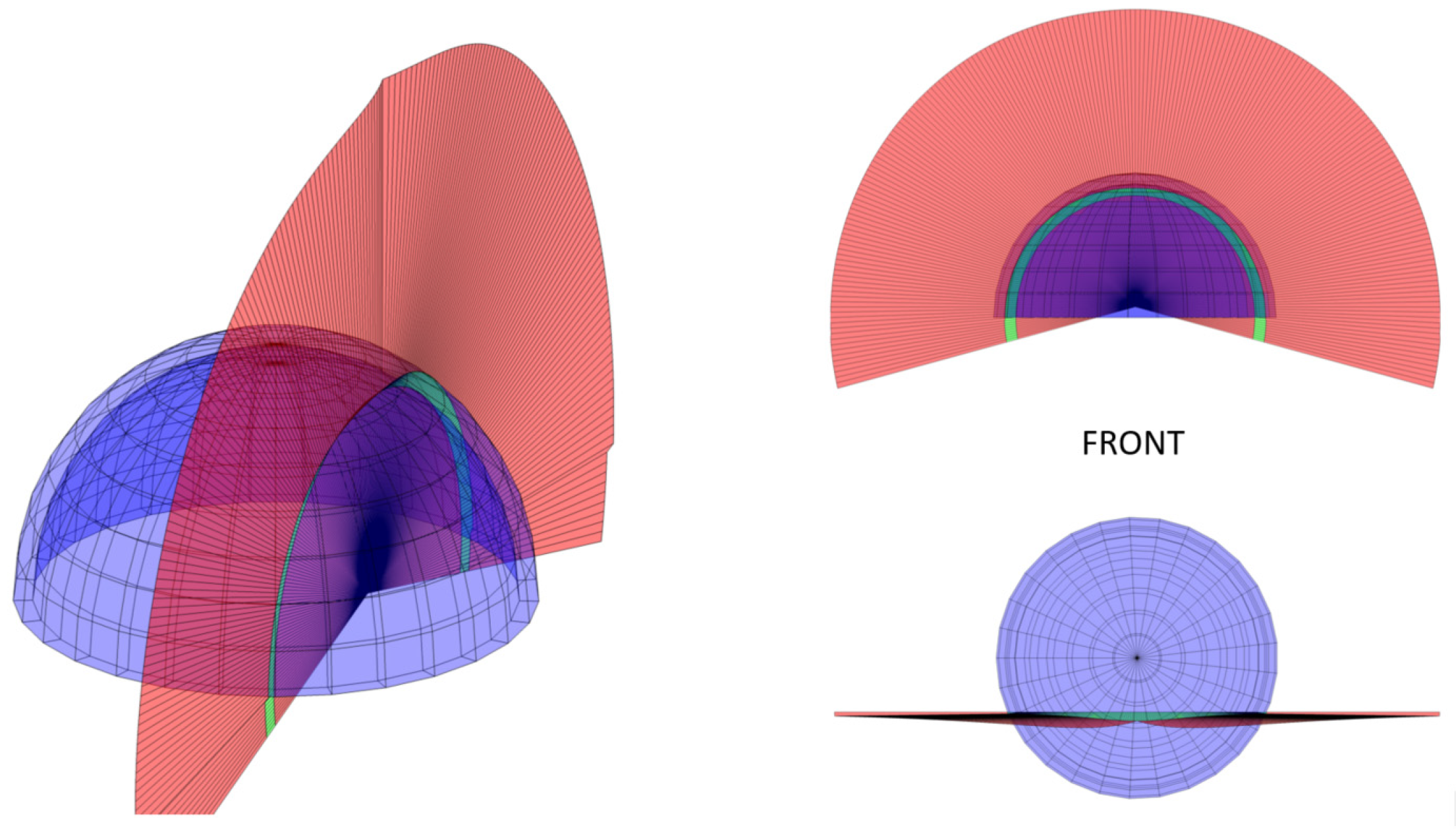
The transparent dome presents a number of refraction interfaces for the LIDAR beam to pass through, which are otherwise not present in a “standard” application in which there is no interface between the LIDAR and the target. At the wavelength used (λ = 905 nm), the transparent enclosure index of refraction is substantial (n = 1.57), and thus the LIDAR beams are sufficiently deflected so as to introduce 3D displacement of the inferred target position and hence distortion of the point cloud. These displacement distortions increase proportionally with increasing range from the LIDAR origin. Furthermore, the off-axis design of the system results in a change in the plane of refraction for each LIDAR beam as a function of the angle about the LIDAR beam axis. This results in the distortions being out-of-plane relative to the LIDAR scan plane and so creates a non-linear distortion of the point cloud.
Figure 1 illustrates the type of geometrical distortion created.
The transparent dome (blue) refracts each of the internally incident LIDAR beams differently depending upon launch angle about the scan axis. The green band shows the non-planar surface containing all beams after the first refraction interface, travelling within the dome material. The red non-planar surface contains all propagated beams thereafter and illustrates additional features such as an inflection point near the zenith. To accommodate the change in refraction plane as a function of LIDAR scan angle, the vector form of Snell’s Law is employed (Equation (1)):
where
are the incident and refracted ray unit vector directions,
are the respective refractive indices of the interface, and
is the interface normal. Application of this equation allows for a correction table to be generated between the true and apparent ray directions over the LIDAR scan plane, and hence target point locations, in turn permitting correction of distortion.
3.4. Optical Distortion Testing
Given the use of off-the-shelf LIDAR systems with known accuracy specifications, the evaluation of ExScan® accuracy was accomplished by a comparison of system performance in terms of geometrical distortion and range accuracy with and without the dome mounted. In the trial, full 1D scans were performed, and a comparison of point locations was made to evaluate distortion.
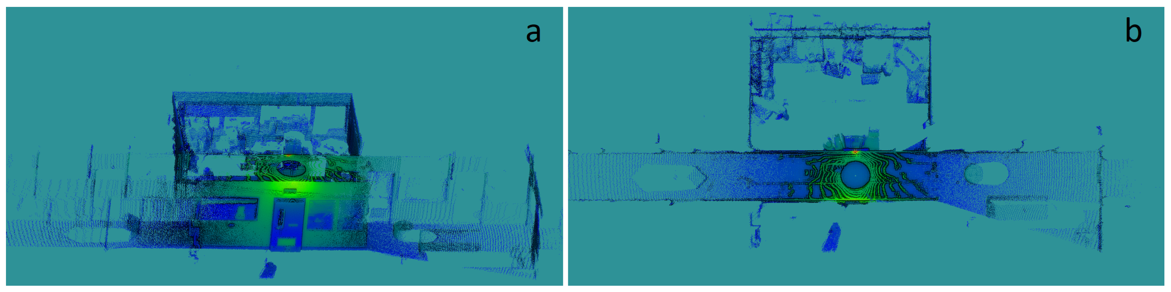
An ExScan
® was rigidly mounted on the ceiling of a hallway with a view as shown in
Figure 2a,b.
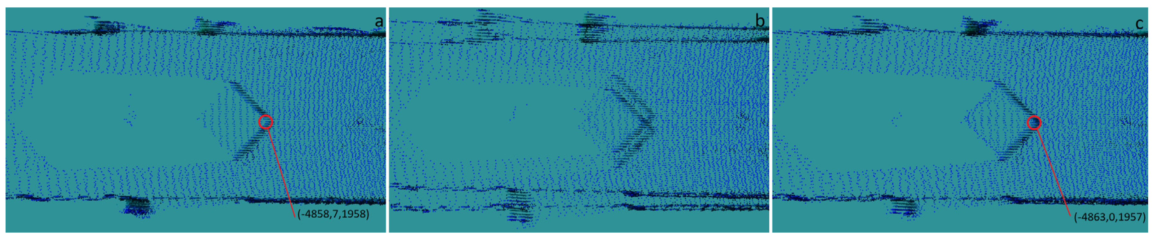
Full scans were completed without the dome, with the dome in place but without corrections, and with the dome and corrections applied. A clear demonstration of these effects can be seen on the imaging of a 0.5 m cube positioned on the floor at 5.2 m from the ExScan
® mounting point in
Figure 3a–c where in
Figure 3a the leading vertical planes are imaged plainly. Artefacts in the scene introduced by the dome without corrections can be seen easily in
Figure 3b and as-corrected in
Figure 3c.
In these point cloud segments, it can be clearly seen that the correction algorithms adequately account for distortions though the transparent dome. To verify, the closest vertex for both the dome-off and corrected with-dome scans were identified in real world xyz coordinates in ExScan’s frame of reference. As shown in
Table 2, the error in measurement is well within the per-point accuracy of the LIDAR scanner.
3.5. Explosion Protection Level (EPL) Rating
Because of the requirement for the enclosure to operate in explosive risk zones, the enclosure was designed to satisfy the requirements of IEC 60079.0:2017 3.2. Compliance with this standard is necessary to receive regulatory approval for use in underground coal mines.
Major considerations influencing the design concentrated on both the metal base to ensure wall thicknesses would achieve pressure and strength compliance, as well as the transparent non-metal dome, in order have sufficient strength (both from internal pressure and external impact tests), and age resistance to the influence of water, dust, and oil.
Once the testing process was complete, as well as unit certification of this design and manufactured enclosures by a registered testing station, a certificate of conformity for the Type 2550 enclosure design was issued. The certificate number is IECEx ExTC 18.0023. Importantly for the industry, the status of this or any other certificate can be confirmed on the IECEx website [
15].
4. Field Testing
Early field trials of the prototype enclosure were deemed essential for any future development and for subsequent plans for commercialisation. This allows identification of any issues that may arise in routine use of the enclosure and generates feedback regarding modification of the design, if necessary. Relevant aspects include:
installation readiness and any issues that arise that hamper installation;
robustness in exposure to “real-world” environments, separate from the testing environments used in certification;
payload performance and the ability to deliver useful data in an efficient manner, unhampered by the enclosure design;
acceptance and interest from the industry, which arguably represents the most indicative measure of the viability of the design.
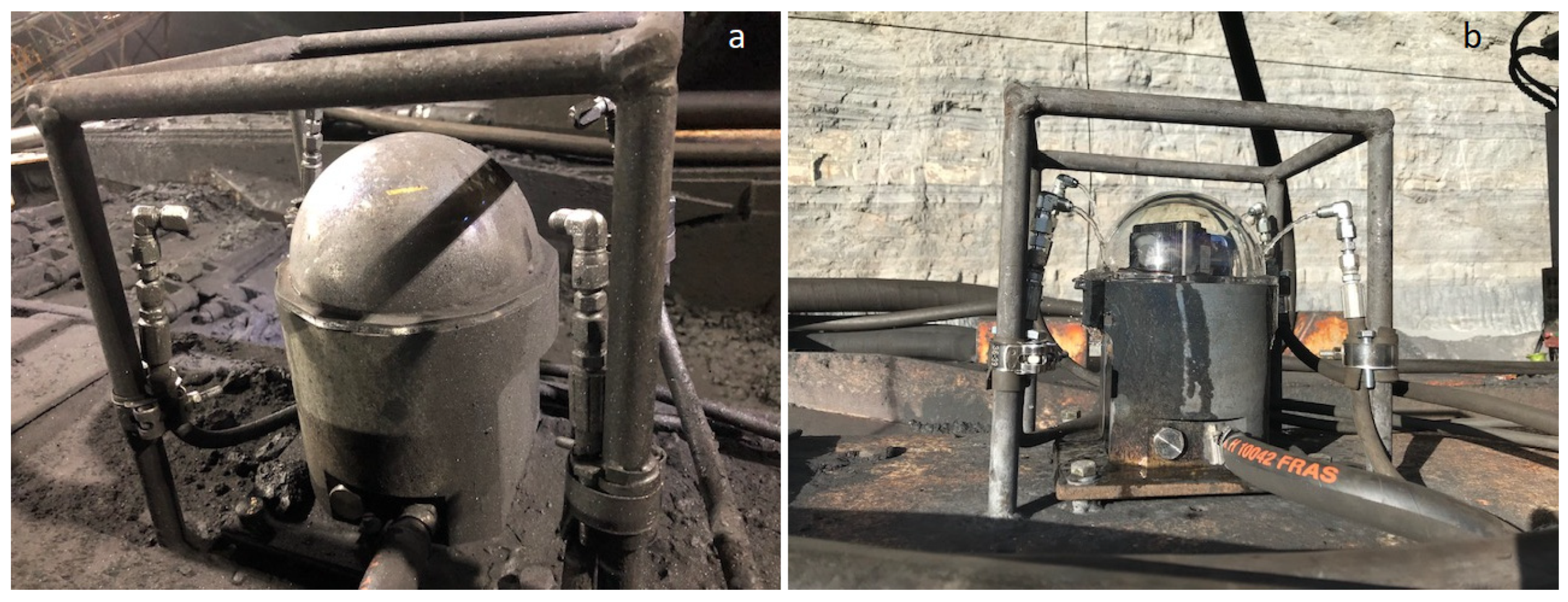
Figure 4 shows two separate enclosures with scanning laser-based sensing payloads deployed in an operational underground mine as part of the field testing phase. This payload/enclosure combination is being commercialised by CSIRO as ExScan
®.
Figure 4 shows the enclosure mounted on a longwall beam stage loader (BSL) and travels with this equipment. In
Figure 4b, the enclosure is mounted to a roof support. Here it can be seen that the enclosure fits within the roof support recess, minimising intrusion into the walkway area below.
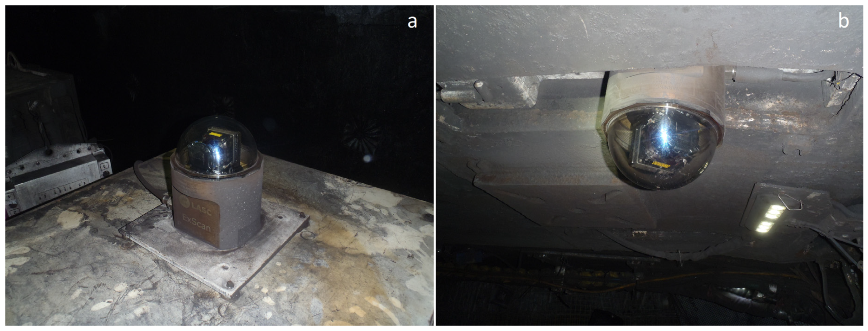
Figure 5 shows an enclosure with ExScan
® deployed in an operational highwall mine. It was mounted to the back of a continuous miner in order to allow mapping of the extracted coal tunnel. In this application, the unit was exposed to very high levels of dust and debris during testing. A water spray system was implemented by the operator in order to clear debris from the unit at hourly intervals.
Figure 5a shows the unit before the water spray clears the dome, with significant buildup of coal dust and debris.
Figure 5b shows how effectively the dome is cleared by using water alone. This unit ran in this configuration for approximately one month, during which time there was no detectable degradation in the quality of the laser scans after each cleaning cycle, and only very minor scratches were observed on the outside of the dome.
It was found that the coatings applied to the domes enabled quick cleaning via water spray and little to no degradation to the optical performance of the payload.
5. ExScan® Payload Experiments and Performance
Figure 6 and
Figure 7 show examples of a LIDAR scan obtained from ExScan
®. This is a tailored system developed by CSIRO in parallel with the development of the enclosure, in order to demonstrate a functional system that is not only compatible with the enclosure but which enables forms of measurement unavailable until now to be performed in explosion risk environments. While LIDAR results are principally presented here, it is noted that the system is fully capable of additionally delivering video imaging, as well as image stitching for a panoramic perspective.
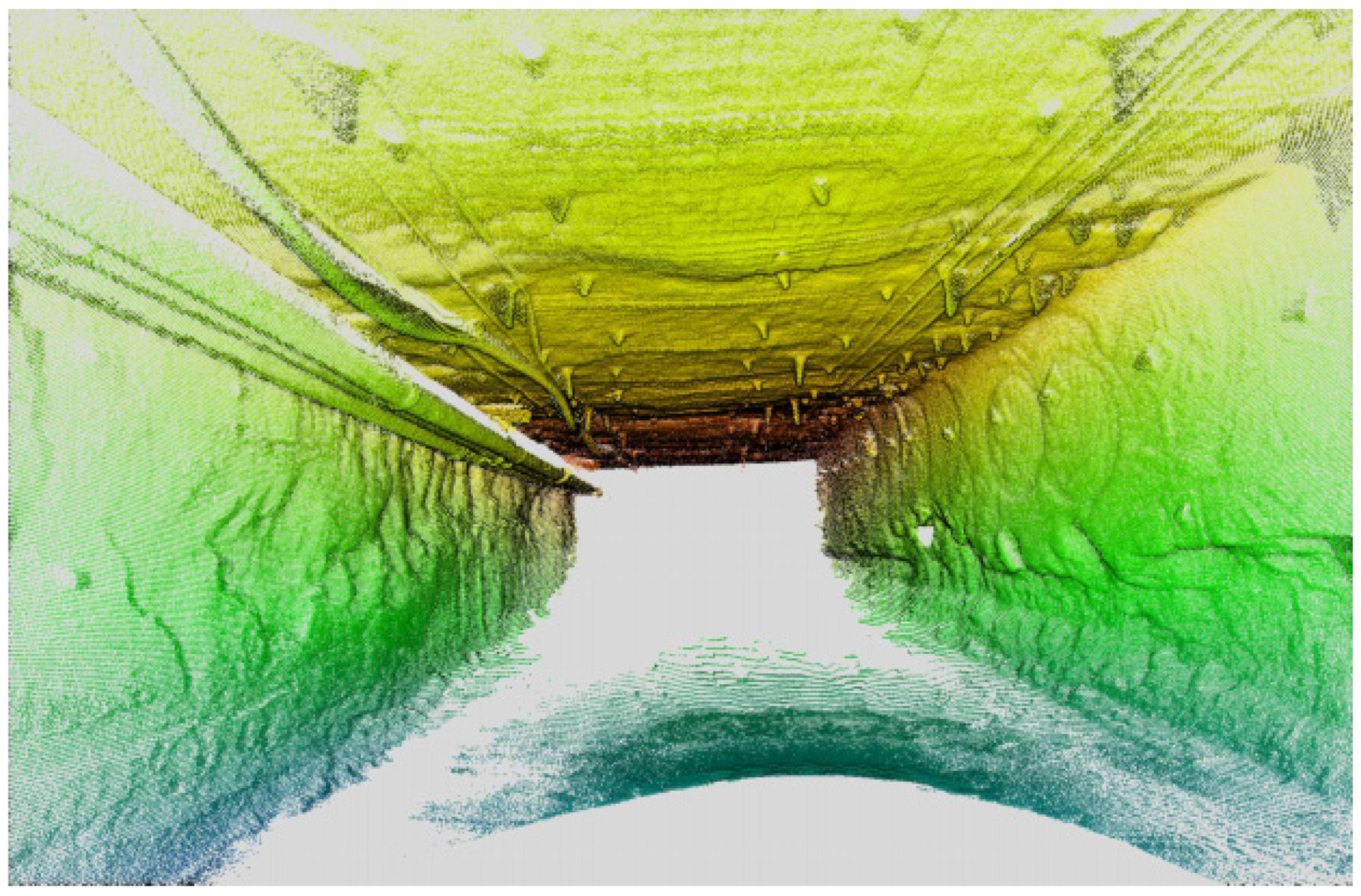
Figure 6 shows a screenshot of a fully three-dimensional point cloud of a gate road from a trial mine site. Note that these results were pre-processed in situ and delivered wirelessly in real time from the installed ExScan
® system to the remote workers operating the equipment. Many features are clearly visible, including the roof bolts and plates, mesh, and service cabling. The spatially accurate structure of the walls and texture detail are also readily apparent, meaning this imagery can enable accurate location of equipment and mapping of the space.
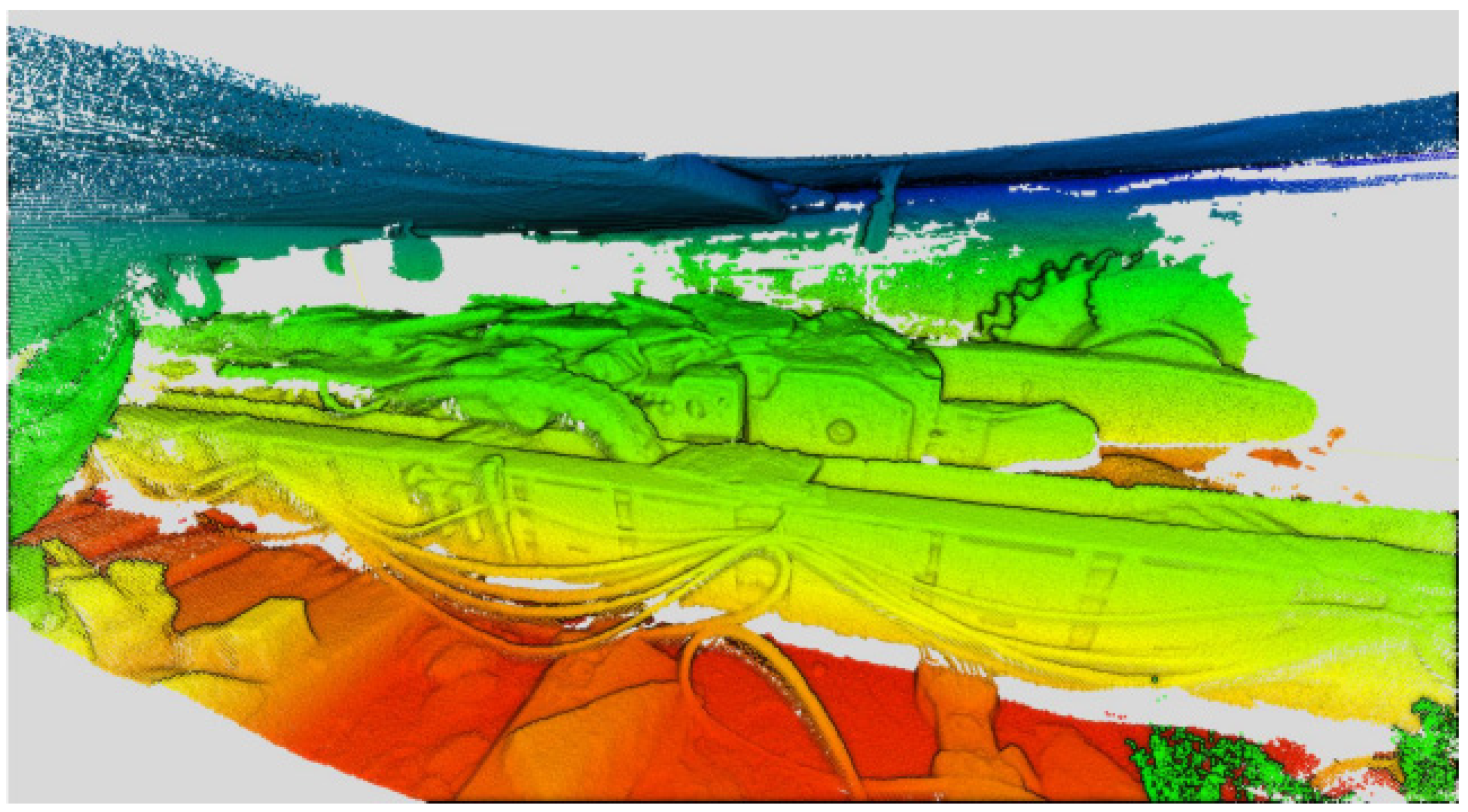
Figure 7 shows a section of longwall imaged using ExScan
®. This scene shows the longwall shearer, armoured face conveyor, and sections of the roof supports, all imaged using the LIDAR payload. With the so-obtained 3D point cloud data, the camera viewpoint is easily changed allowing accurate perspectives of the equipment that would otherwise not be physically possible; in this figure, the camera viewpoint would be in rock above the roof of the roadway.
It should be noted that these 3D renderings are made from point clouds that have been mathematically corrected for optical distortion introduced by refraction of the LIDAR laser through the dome material. In parallel with development of the enclosures, these calibration correction algorithms were also developed and tested on scenes to ensure all distortions of the 3D point clouds were minimised. In practice this results in crisp, un-blurred, and undistorted reproduction of features such as walls and ceilings of a room, which would otherwise be distorted without these corrections applied. The extent of the scenes is also worth noting. These are limited by the range of the LIDAR, which is generally many tens of meters in surface applications but is significantly reduced in the underground coal mining context due to the low reflectivity of coal. The use of anti-reflection coatings tuned for the LIDAR laser wavelength allowed these point clouds to be as detailed and extensive as they are.
6. Utilisation
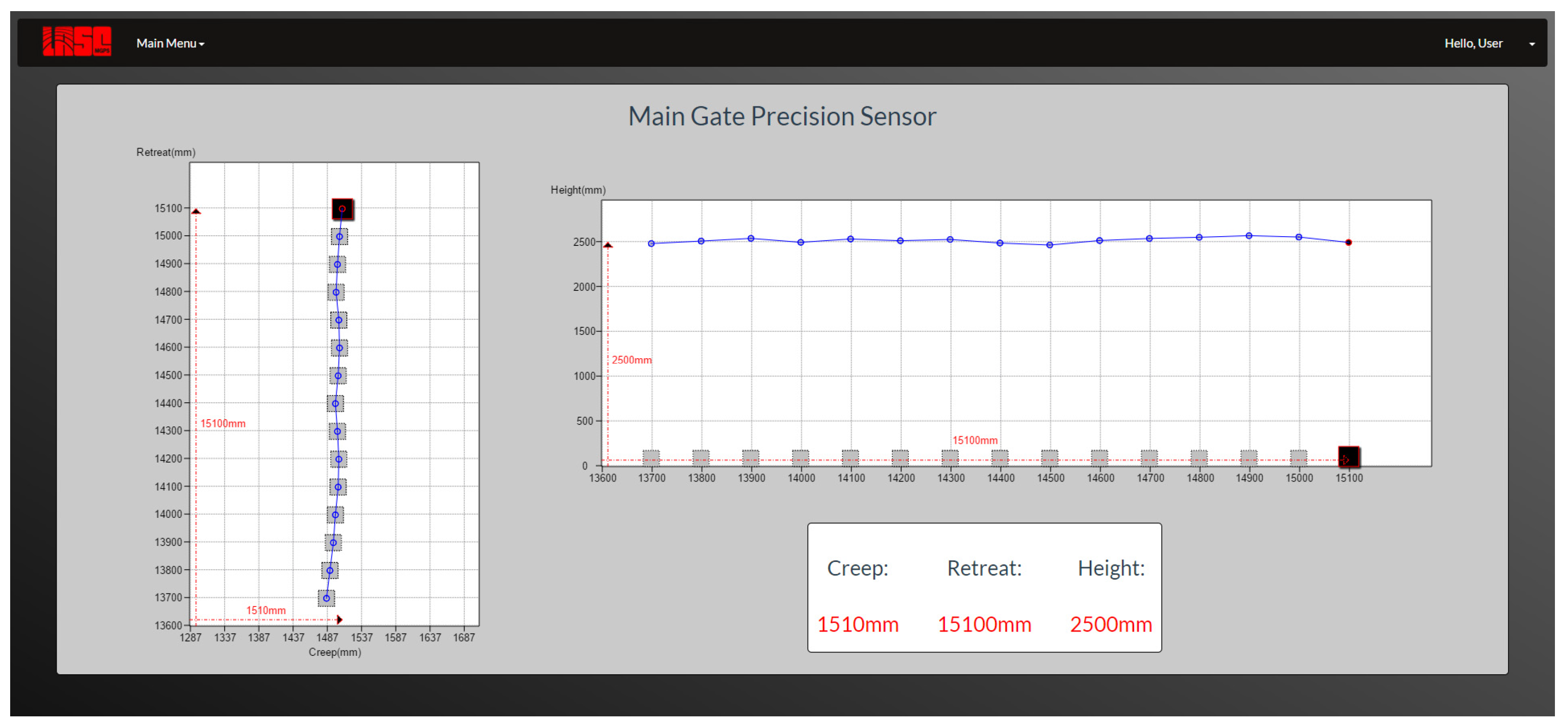
Based on the imaging obtained during ExScan® experiments, an immediate application for the technology was identified. One critical guidance component required to achieve remote control or autonomous operation of an underground coal longwall mining system is the measurement of the clearance distance between the equipment and the side of the roadway tunnel. Known as “creep” measurement, this distance must typically be maintained within 200mm of a target line to ensure that the 10,000 tonnes of connected longwall production equipment remains centred on the desired trajectory. Excursions outside this desired alignment can lead to severe production limiting events, such as the longwall system interacting with the roadway side wall.
From
Figure 6, it can be seen that the identification of physical distance from an ExScan
® unit mounted on the roadway equipment to the tunnel walls or roof is a straightforward task. This value can be used in steering systems to provide regular corrections to ensure that the longwall system stays within tolerance.
Figure 8 displays a view of the critical measurements generated by ExScan
® systems to provide longwall steering capability.
7. Conclusions
This project has demonstrated that it is possible to design, manufacture, and successfully deploy a low-cost enclosure that is capable of housing optical equipment that is able to provide 360-degree imagery of the environment while also meeting all the requirements of the IECEx Standards for Ex d protection in hazardous areas.
Previously it had not been possible to use state-of-the-art optical imaging technologies in explosive atmospheres due to lack of suitable enclosures. The enclosure that was designed and certified is beginning to seed various different use-cases. For example these include mapping with either radar, cameras, or LIDAR systems for a wide range of different applications. These are high-value applications, particularly in the development of remote operations and management of mine automation systems, vital components of the digital mine.
The success of this project has enabled the development of ExScan®, a 3D laser mapping system for use in hazardous environments. This technology is already in early stages of commercialisation, and currently there are 10 complete systems running in production environments in coal mines around Australia.
Author Contributions
Conceptualization, P.R.; methodology, P.R., J.M. and M.D.; software, P.R., J.M. and M.D.; validation, P.R., J.M. and M.D.; formal analysis, J.M.; investigation, P.R.; resources, M.D.; data curation, P.R.; writing—original draft preparation, M.D.; writing—review and editing, J.M. and M.D.; visualization, M.D. and J.M.; supervision, P.R.; project administration, P.R.; funding acquisition, P.R. All authors have read and agreed to the published version of the manuscript.
Funding
This research was funded by Australian Coal Association Research Program (ACARP) grant number C26052.
Acknowledgments
The authors wish to thank the Australian coal industry, in particular ACARP, for supporting this research.
Conflicts of Interest
The authors declare no conflict of interest. The funders had no role in the design of the study; in the collection, analyses, or interpretation of data; in the writing of the manuscript, or in the decision to publish the results.
References
- Che, E.; Jung, J.; Olsen, M.J. Object Recognition, Segmentation, and Classification of Mobile Laser Scanning Point Clouds: A State of the Art Review. Sensors 2019, 19, 810. [Google Scholar] [CrossRef] [PubMed]
- Lynch, L.; Newe, T.; Clifford, J.; Coleman, J.; Walsh, J.; Toal, D. Automated Ground Vehicle (AGV) and Sensor Technologies-A Review. In Proceedings of the 12th International Conference on Sensing Technology (ICST), Limerick, Ireland, 4–6 December 2018. [Google Scholar]
- Baxter, J.A.; Merced, D.A.; Costinett, D.J.; Tolbert, L.M.; Ozpineci, B. Review of Electrical Architectures and Power Requirements for Automated Vehicles. In Proceedings of the 2018 IEEE Transportation Electrification Conference and Expo (ITEC), Long Beach, CA, USA, 13–15 June 2018. [Google Scholar]
- Shaffer, G.; Stentz, A. A robotic system for underground coal mining. In Proceedings of the 1992 IEEE Conference on Robotics and Automation, Nice, France, 12–14 May 1992; pp. 633–638. [Google Scholar]
- Roberts, J.M.; Duff, E.S.; Corke, P.I. Reactive navigation and opportunistic localization for autonomous underground mining vehicles. Inf. Sci. 2002, 145, 127–146. [Google Scholar] [CrossRef]
- Ferrein, A.; Scholl, I.; Neumann, T.; Krückel, K.; Schiffer, S. A System for Continuous Underground Site Mapping and Exploration. In Aerial Robotic Systems; IntechOpen: Rijeka, Croatia, 2019. [Google Scholar]
- Ren, Z.; Wang, L.; Bi, L. Robust GICP-Based 3D LIDAR SLAM for Underground Mining Environment. Sensors 2019, 19, 2915. [Google Scholar] [CrossRef]
- Raval, S.; Banerjee, B.P.; Singh, S.K.; Canbulat, I. A Preliminary Investigation of Mobile Mapping Technology for Underground Mining. In Proceedings of the IGARSS 2019 IEEE International Geoscience and Remote Sensing Symposium, Yokohama, Japan, 28–31 July 2019; pp. 6071–6074. [Google Scholar]
- International Electrotechnical Commission (IEC). IEC System for Certification to Standards Relating to Equipment for Use in Explosive Atmospheres; IEC: Geneva, Switzerland, 2014. [Google Scholar]
- Department of Natural Resources, Mines and Energy. Underground Electrical Equipment and Electrical Installations. In Recognised Standard 01 M.a.E.; Department of Natural Resources, Mines and Energy: Qld, Australia, 2018. [Google Scholar]
- Standards Australia. Explosive Atmospheres, Part 0: Equipment—General Requirements (IEC 60079-0:2017 (ED.7.0); Standards Australia: Sydney, Australia, 2019. [Google Scholar]
- Ralston, J.; Hargrave, C.; James, C.; Chai, Z.; McPhee, P. ACARP C26051: An On-machine Bolting and Geotechnical Monitoring System; ACARP: Brisbane, Australia, 2019. [Google Scholar]
- Reid, P.; Malos, J. ACARP C26052 Low Cost Laser and Video 3D Imaging Equipment; ACARP: Brisbane, Australia, 2019. [Google Scholar]
- McPhee, R.; Reid, P.; Malos, J. ACARP C1021 Full Panorama View (360°) Video and Laser FLP Enclosure, 2018; ACARP: Brisbane, Australia, 2019. [Google Scholar]
- IECEx. Search Certificate/Reports. 2020. Available online: http://iecex.iec.ch/iecex/exs.nsf/ex_eq.xsp?v=e (accessed on 18 January 2020).
© 2020 by the authors. Licensee MDPI, Basel, Switzerland. This article is an open access article distributed under the terms and conditions of the Creative Commons Attribution (CC BY) license (http://creativecommons.org/licenses/by/4.0/).


