Article

Effect of Ambient Parameters on the Temperature Distribution of Photovoltaic (PV) Modules

1
Doctoral School of Mechanical Engineering, Szent Istvan University, 2100 Godollo, Hungary
2
Department of Energy Systems Engineering, Koforidua Technical University, KF-981 Koforidua, Ghana
*
Author to whom correspondence should be addressed.
Resources 2019, 8(2), 107; https://doi.org/10.3390/resources8020107
Submission received: 20 May 2019 / Revised: 4 June 2019 / Accepted: 6 June 2019 / Published: 9 June 2019

Abstract

:
This paper pivots around the influence of thermal parameters on the temperature distribution of a (PV) module. The solar irradiance, ambient temperature, and heat transfer coefficient were examined for four differently manufactured solar modules. A finite element analysis of the solar system was carried out to simulate the prevailing thermal conditions. It was determined through analysis that the heat transfer coefficient had a significant effect on the boundaries of the PV modules. The temperature gradient was relatively high at the boundary, whereas the main body had the least deviation from the mean value of experimental data. The high value of irradiance is favorable for a large PV system, while the heat transfer coefficient should be low for avoiding undulation of the thermal gradient across the plate. The temperature distribution on the surface of the PV modules largely depended on the geometry and the material used for the design purpose.

Graphical Abstract

1. Introduction

The temperature of a solar PV module is a key factor in the photovoltaic conversion process. Thermal modeling of a solar module provides analytical insight into a PV system used for power generation as the characteristic parameters of any PV module are a dependent function of the ambient conditions of the installation area. Furthermore, it also demarcates the technological drawbacks of different PV systems used in specific conditions. In the same context, some applied research has been conducted, which is compiled in the literature.
In the photovoltaic conversion process of solar modules, about 13–20% of incident solar radiation is converted into Direct Current (DC) electricity. The remaining part is converted into heat [1]. Additionally, the PV module generates heat due to the photovoltaic action in addition to the heating that occurs as a result of the energy radiated at the infrared wavelength of the solar spectrum [2]. It has been reported that PV module power output decreases by 0.4–0.5% for 1 °C increase in temperature above the standard operating temperature, depending on the temperature coefficient of the power of the module [3]. The impact of temperature on the performance of PV systems, therefore, requires a thorough understanding of the temperature behavior of PV modules in operation.
The heat energy balance in a PV module is influenced by factors such as absorbed incident radiation, the transmitted or absorbed radiation, and the conversion losses, which are caused by the mutual interaction of physical bodies, entropy generation, recombination, or parasitic absorbance [4,5]. Siddiqui et al. [6] investigated the thermal performance of PV modules through a numerical simulation method. Thermal models, in the case of cooling and non-cooling, is studied and validated while examining the influence of ambient temperature, irradiance, and wind speed on the temperature distribution in PV modules [6]. A three-dimensional thermal model is adopted to examine the temperature distribution of a solar cell layer and to analyze the thermal performance of a polycrystalline silicon module, as well as finding the effect of the back sheet of the module on the temperature distribution, applying single factor analysis. The results show that the module temperature varies linearly, with a temperature gradient of 0.82 K/mm, when Tedlar Polyester Tedlar (TPT) back sheet thickness varied from 0.10 mm to 0.70 mm [7].
In another study, Armstrong and Hurley has developed a dynamic thermal model for a PV module. It has been used to determine the thermal response time of a PV module under real operating conditions. The proposed model incorporates the atmospheric conditions, the effects of PV panel material composition, the mounting structure, and the heat-loss mechanisms to verify the thermal behavior of a PV module for low to high wind speeds. The temperature response of the PV modules as Resistance-Capacitance (RC) circuits is introduced, which included an investigation of the material composition of the modules. The convective heat transfer losses for both free and induced wind are analysed and considered in terms of their electrical properties by means of an RC circuit, while investigating the heat transfer from the surface of the PV module under varying wind speeds. The thermal model has been verified by experimental results from low to strong wind speeds [2].
The temperature behavior of a solar cell layer and the module’s thickness are examined using a three-dimensional thermal model. The effects of environmental conditions and the adjacent cell interval on the temperature distribution of the module have been investigated. A three-dimensional thermal model of a polycrystalline PV module is solved using the finite element software platform ANSYS12.1/Multiphysics LS-DYNA. The temperature distribution of the cell layer and the module’s thickness direction are analysed. The effects of environmental conditions, such as solar irradiance, wind speed, ambient temperature, and adjacent cell interval, on the temperature distribution of PV module are investigated. The model boundary is considered to be adiabatic and the thermophysical parameters of all the materials are assumed to be isotropic and independent of temperature. The reflectivity(ρ), transmissivity(τ), and absorptivity (α) of all materials are also assumed to be one. Their results have shown the solar cell processing the highest temperature of 331.76 K near its center [8]. Therefore, it is necessary to investigate the behavior of the PV system at the dynamic boundary condition. A mechanical meshing system coupled with a finite volume method computational fluid dynamics (CFD) system has been used to simulate the airflow above and below the panel. The wind velocity, tilt angle, and ambient temperature has been varied to create different working conditions. The surface convection coefficients resulting from the CFD calculations has been introduced into the transient thermal analysis system in ANSYS, which provided the heat transfer results within the solar panel. The results from the CFD simulation have been introduced into the thermal model, and a mapping of temperature distribution has been performed. It has been concluded that precision is low and needs a better definition of the air domain to eliminate of flow too close to the boundaries, and it also requires the improvement of the time discretization for higher resolutions [9].
In this study, the system analysis of the solar modules is carried out using a three-dimensional model. The finite element method (FEM) is used to determine the temperature distribution across the PV module. The prediction of the thermal behavior of the PV module is performed at varying ambient conditions. The thermal analysis of the PV modules can be achieved through a suitable assessment of their behavior via mathematical modeling; therefore, the proposed scheme helps to pinpoint the area of improvement required for a much better prospect of power generation through the existing technologies.

2. Materials and Methods

2.1. Thermal Modeling and Finite Element Analysis (FEA)

The temperature distribution was assumed to be the function of position and time, T = f ( x , y , t ) . Thermal modeling of the system is performed using MATLAB software (MathWorks, Natick, MA, USA), where each PV module is kept under observation for 160 minutes. To determine the heat transfer coefficient between the plates and air at atmospheric pressure, the PV plates were kept at an angle of 45°. The white box modeling scheme was adopted to predict the thermal behavior of the PV models. The governing partial differential equation (PDE) considered for the modeling is given by Equation (1). The absolute tolerance of solution was set to 0.001, whereas the relative tolerance between the size of solutions was 0.01. The Dirichlet (or first-type) boundary condition was fixed for all the models, whereas the Neumann (or second type) boundary condition depended on the time derivative of temperature. Samples of the captured infrared (IR) images of the studied PV modules are shown in Figure 1. The varying conditions are represented through a color map. The heat transfer model-based modeling has been reviewed in literature [10,11,12,13]; however, the concept of finite element analysis to find a solution of the 3D partial differential through the triangular meshing of the PV plates reduces computational efforts for the complex geometries. It is cumbersome to describe the elementary function over a complex structure, therefore the methodology, finite element method (FEM), approximates the computational domain via a combination of simple geometrical objects. The triangular mesh is employed to discretize the PDE on the mesh and generate an equation for the approximation of the solution. However, one has to keep the approximated solution close to the original output, therefore a smaller number of blocks are generally used to approximate the solution. The solution in each block should be simple, thus it becomes easier to determine the solution in the small domain. The polynomial equations are the most flexible, and they have a good convergent property for a small region. Some basic parameters related to the PDE can be computed through Equations (2), (3) and (4).
The following governing Equation (1) is used for modelling the temperature distribution across the PV module.
α T t · ( Δ T ) = Q L c + N u   ¯ L c ( T e x t T ) .
where α, thermal diffusivity; T, temperature; Q, heat flux; T e x t , ambient temperature
Characteristic length for a plate can be expressed by Equation (2)
L c = A r e a   o f   p l a t e P e r i m e t e r   o f   p l a t e .
Neumann boundary condition for a given thermal system (Equation (3))
I )   n · ( k ( T ) ) + h T = g .
Dirichlet boundary condition for a given thermal system (Equation (4))
II )   T ( t , 0 ) = T k , 1   a n d   T ( t , L ) =   T k , 2 ;   k   =   A ,   B ,   C ,   D
Here k represents the boundary condition for a particular module.
The Tk,1 and Tk,2 are boundary temperature at the bottom (subscript 1) and the top (subscript 2) edges of the PV modules.
The Grashoff number for an inclined plate can be expressed by Equation (5)
G r = G r V sin θ
where ‘θ’ is the inclination of the PV module and G r V is the Grashoff number for the vertical plate (Equation (6)), whereas the Prandtl number is given by Equation (7).
G r V = L c 3 β g Δ T ν 2
P r =   μ C p k .
Here-
  • P r is the Prandtl number
  • μ (N-s/m2) is the dynamic viscosity
  • C p . (kJ/kg-K) is the specific heat capacity
  • k (W/m-K) is the thermal conductivity
  • β (1/K) is the coefficient of thermal expansion
  • ν (m2/s) is the kinematic viscosity
The average Nusselt number [14] for a plate is derived through correlation given by Churchill and Chu (Equation (8)). The Equation (8) is only valid for G r   · Pr < 10 9 .
N u ¯ = [ 0.68 + 0.67 ( G r · P r ) ( 1 4 ) { 1 + ( 0.492 P r ) ( 9 16 ) } ( 4 9 ) ]

2.2. Experimental Set-Up

The study is performed at the Solar Energy Laboratory in Szent Istvan University, Godollo, Hungary, which lies on the coordinates 47°35’39” N, 19°22’0” E. The four different PV systems (DUNASOLAR, SOLARWATT, SOLAREX, RWE SCHOTT SOLAR) were selected to analyze the relative variation of temperature distribution with varying thermal conditions. The different company PV modules allow the determination of the reproducibility of the modelling scheme; therefore, the validity of a solution can also be established. The two different configurations of modules—front glass and Tedlar back sheet assembly, and front glass back glass assembly—are used for experimental purposes. Module specifications are shown in Table 1.
The modules fixed to a support to face true south are shown in Figure S1. The measuring instrument and the other materials employed in the acquisition of data are shown in Figure S2. The modules were kept at similar ambient conditions. An infrared (IR) camera (NEC Avio Infrared Technologies, Shinagawa-Ku, Tokyo, Japan) with specifications listed in Table 2 was used to capture the IR images. The solar radiation data were calibrated through a Kimo solarimeter LSL 200 (Kimo instruments, Bernard Moulinet, Montpon-Ménestérol, France) at the inclination of the PV modules (resolution 1 W·m−2, accuracy 5%). The ambient temperature was measured using HT-9815 Xintest Pt-100 sensors (±0.1 °C) (Dongguan Xintai Instrument, Dongguan, Guangdong, China). An MS6252A-anemometer (±3%) (Mastech, Qingxi, Guangdong, China) was used to determine the wind speed measurements. Report Generator Lite software (NEC Avio Infrared Technologies, Shinagawa-Ku, Tokyo, Japan) was used to process the captured IR images of the modules. The emissivity of the module surface was set to 0.85 for the measurement [15,16,17].

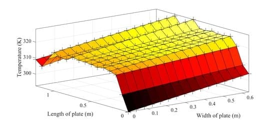
3. Results and Discussion

The effects of ambient parameters on the solution were determined through the Finite element method (FEM). The variation in the temperature distribution at the changing value of the irradiance, G (W·m2), on the numerical solution is illustrated in Figure 2a,b (Module A (DUNASOLAR)). With the increasing in G, the temperature distribution scale of the plate increased by 278.5 K at the top and bottom edges of the plates, whereas the change increased up to 298 K at the left and right sides of the plates. The overall temperature offset of 292 K was found at all other points on the surface. The temperature remained constant for both values of G (750 W·m−2, 850 W·m−2), but the temperature of the PV system was elevated. The variation of the average heat transfer coefficient is shown in Figure 2c,d. The effect of change in the average heat transfer coefficient ( h   ¯ ) was predominately seen at the air-exposed edges of the PV system. The heat flux-loss increased by 17% with an increase in h   ¯ by 17%; thus, the influence of heat-transfer coefficient was directly proportional to the heat flux-loss at the left and right edges of the surface, while the temperature remained the same as other parts of the plate. The ambient temperature and its significant effect on the system are illustrated in Figure 2e,f. The nominal increases in temperature of the PV system with respect to change in the ambient temperature. The temperature of plate increased within a range of 0.67–4.16% when the ambient temperature scaled shifted up by 10%. Thus, it can be concluded that the relative effect of ambient temperature as compared to the heat transfer coefficient is low on the temperature distribution scale for the PV system without a frame (Module A). The predicted solution for the PV modules is compared with the experimental results in Figure 3a,b. The behavior predicted module perfectly simulates the experimental trend at an irradiance of 800 W·m−2 and the ambient condition of 298 K. The module B (SOLARWATT) was subjected to a similar condition to ensure reproducibility and validity of the proposed model. The module B is also a frame-less module, and a similar trend has been noticed in temperature distribution. The effect of irradiance fluctuation is shown in Figure 4a,b. At 6.6% surge in the irradiance level, the overall temperature of module B (Figure 4) increased by 1.5–3.8%, whereas it was 1.86% to 8.8% for module A (DUNASOLAR) with a 13.33% increase in ‘G’. The behavior of the PV modules with respect to the average heat transfer coefficient ( h ¯ ) is illustrated in Figure 4c,d. The temperature of the left and right edges of module A and module B (Figure 4) decreased by 13% and 12.5%, respectively, for a 17 % rise in h   ¯ . The effect of ambient temperature on the PV modules is shown in Figure 4e,f. The temperature scale gets shifted up by 1.5% with a 10% rise in the ambient temperature (Figure 4). A comparative study of the experimental results with the predicted solution is visualized in Figure 5a,b. Unlike the module A, module B (Figure 5) provided better prediction at a higher level of irradiance of 850 W·m−2. The reason for the relative increase in the irradiance level of similar kind of module is their characteristic length as it affects the velocity profile across the surface of the PV system. Therefore, a rise of 6.6% is demanded to compensate for the temperature drop due to heat loss across the plate.
The effect of ‘G’ on the framed PV system (SOLAREX) is shown in Figure 6a,b. Unlike the module A and module B, the framed PV module (module C) had a 14% increase in temperature at the left and right edges of plate as a 13.33% rise in the value of ‘G’ occurred; which is 5.2% higher than for module A. The overall temperature of the plate, except the edges, dropped by 7.35%, which is constant in the frame-less modules (A and B). The influence of the average heat transfer coefficient is depicted in Figure 6c,d. A 20% temperature drop (Figure 6) at the edges of plates of module C (SOLAREX) occurred, which is 7% and 6.5% more than module A and module B, respectively. The effect of ambient temperature is illustrated in Figure 6e,f. The temperature of the PV modules increased by 8.33% at the left and right boundaries of surface, whereas it was 1.5–4.16% for the frame-less modules (SOLAREX and DUNASOLAR). Comparison of the predicted solution with the experimental result is shown in Figure 7a,b. The numerical solution provided a better convergence at 800 W·m−2, however, the temperature at the left and right edges of the predicted solution is marginally high, whereas the top and bottom edges are not incongruent with the experimental data. The effect of irradiance (G) on the PV module in illustrated in Figure 8a,b. The module C (RWE SCHOTT SOLAR) had a major variation in temperature distribution at the edges of the surface (Figure 8.). A 1.02% to 7.38% elevation of temperature was observed for a 6.66% increase in the irradiance, G. Likewise the SOLARWATT, the RWE SCHOTT SOLAR provided a better convergence at the irradiance of 850 W·m−2. The effect of the heat transfer coefficient on the numerical solution is shown by Figure 8c,d. The heat flux decreased by 67% at the left and right boundaries of the PV plates due to the 17% increase in the heat transfer coefficient, which is 50% more than that of module A and module B. The influence of a rise in the ambient temperature is relatively high on the RWE SCHOTT SOLAR (Module D) (Figure 8e,f). A 10% rise in the ambient temperature led to 13.33% increase in the PV surface temperature, whereas the temperature at the top and bottom edges remained unaffected. Although the heat flux-loss decreased at the left and right edges by 87.5%, it is equally compensated by edges along the width of the plate. Comparison of the predicted solution with the experimentally derived results is illustrated in Figure 9a,b. Overall uniformity of temperature was obtained on the surface of the PV modules, but the temperature obtained through experimental data marginally decreased at the bottom edge of the inclined plate. The edges along the length of the plate had a relatively high-temperature gradient.

4. Conclusions

The Finite Element Analysis (FEA) was carried out to discretize the solution of the PDE of the heat transfer module. The effect of irradiance, heat transfer coefficient, and the ambient temperature on the temperature distribution on the surface of the PV modules was assessed by doing a comparative analysis of different solar modules. For the smooth functioning of the PV modules, it is required to reduce thermal losses at the edges and surface of the plates. Moreover, the predicted solution did not overshoot the experimental values, therefore the performance of the PV modules has not been deteriorated by the mathematical solution. The values of parameters obtained through a mathematical solution has not extrapolated the range of solution. It was observed that the temperature distribution across the plate was uniform in the glass-based (Tedlar-free) modules, whereas the heat loss along the edges was higher in the Tedlar based modules. The range of variation of temperature for all the PV modules was in the domain of 295 K to 325 K, whereas it varied from 293 K to 325 K for experimentally obtained data. The temperature gradient and heat flux were relatively high at the edges, however, the range of variation of temperature at other points of PV plates was between 290 K to 318 K. The benefit of this study assists in determining whether the cell temperature is being affected by the ambient conditions. If the temperature of the PV surface rises beyond the demarcated level, the open circuit voltage of the system gets affected, as does the power output of the modules. For the smooth running of the PV system, it must be ensured that the temperature gradient across must be minimal. The frame-less modules had the least temperature gradient across the PV modules, therefore the DUNASOLAR and the SOLARWATT are more compatible for the smaller power unit. The reproducibility of the module was checked with different solar modules and it was found that the range of tolerance had not been violated by the proposed FEM methodology. The excessive heat loss around the periphery of the PV modules causes undue fluctuation of energy output for those regions where the ambient temperature is not steady with time, therefore the central European region requires those PV modules which are more energy efficient in the context of energy loss since the rapid warming or cooling is not suitable for the non-framed modules (DUNASOLAR and SOLARWATT). In terms of thermal analysis, the distribution of temperature must be uniform throughout the plate. Voltage of the individual cell is a function of temperature; hence it must be similar, else likelihood of hotspot formation increases. On the other hand, in those geographical locations where the temperature is relatively high, the framed modules (SOLAREX and RWE SCHOTT SOLAR) would be much more effective, such as in the South Asian region, since the deviation of the modules temperature from the Nominal operating cell temperature (NOCT) is the least (Figure 6e,f and Figure 8e,f).

Supplementary Materials

The following are available online at https://www.mdpi.com/2079-9276/8/2/107/s1, Figure S1: Studied solar PV modules, Figure S2: Data acquisition Instruments.

Author Contributions

Software, visualization and writing/revision original draft, and thermal analysis and its interpretation with the proposed mathematical solution are given by A.D.; data curation, writing/revision original-draft and funding acquisition are provided by D.A.

Funding

“This research received no external funding” and “The APC was funded by Divine Atsu”.

Acknowledgments

This work was supported by the Stipendium Hungaricum Programme and by the Doctoral School of Mechanical Engineering, Szent István University, Gödöllő, Hungary.

Conflicts of Interest

The authors declare no conflict of interest. The funder had no role in the design of the study; analyses, or interpretation of data, or in the decision to publish the results.

References

  1. Tonui, J.; Tripanagnostopoulos, Y. Air-cooled PV/T solar collectors with low cost performance improvements. Sol. Energy 2007, 81, 498–511. [Google Scholar] [CrossRef]
  2. Armstrong, S.; Hurley, W. A thermal model for photovoltaic panels under varying atmospheric conditions. Appl. Eng. 2010, 30, 1488–1495. [Google Scholar] [CrossRef]
  3. Skoplaki, E.; Palyvos, J. On the temperature dependence of photovoltaic module electrical performance: A review of efficiency/power correlations. Sol. Energy 2009, 83, 614–624. [Google Scholar] [CrossRef]
  4. Clugston, V.; Basore, P.A. Modelling free-carrier absorption in solar cells. Prog. Photovolt. 1997, 52, 29–239. [Google Scholar] [CrossRef]
  5. Vogt, M.R.; Holst, H.; Winter, M.; Brendel, R.; Altermatt, P.P. Numerical Modeling of c-Si PV Modules by Coupling the Semiconductor with the Thermal Conduction, Convection and Radiation Equations. Energy Procedia 2015, 77, 215–224. [Google Scholar] [CrossRef] [Green Version]
  6. Siddiqui, M.U.; Arif, A.; Arif, A.F.M. Electrical, thermal and structural performance of a cooled PV module: Transient analysis using a multiphysics model. Appl. Energy 2013, 112, 300–312. [Google Scholar] [CrossRef]
  7. Zhou, J.-C.; Zhang, Z.; Liu, H.-J.; Yi, Q. Temperature distribution and back sheet role of polycrystalline silicon photovoltaic modules. Appl. Eng. 2017, 111, 1296–1303. [Google Scholar] [CrossRef]
  8. Zhou, J.; Yi, Q.; Wang, Y.; Ye, Z. Temperature distribution of photovoltaic module based on finite element simulation. Sol. Energy 2015, 111, 97–103. [Google Scholar] [CrossRef]
  9. Assila, H.; Essadiqi, E.; Faqir, M.; Meziane, M.; Ghanameh, F.; Ahzi, S. Numerical simulation of photovoltaic panel thermal condition under wind convection. In Proceedings of the 2016 International Renewable and Sustainable Energy Conference (IRSEC), Marrakech, Morocco, 14–17 November 2016. [Google Scholar]
  10. Jones, A.; Underwood, C. A thermal model for photovoltaic systems. Sol. Energy 2001, 70, 349–359. [Google Scholar] [CrossRef]
  11. Hammami, M.; Torretti, S.; Grimaccia, F.; Grandi, G. Thermal and Performance Analysis of a Photovoltaic Module with an Integrated Energy Storage System. Appl. Sci. 2017, 7, 1107. [Google Scholar] [CrossRef]
  12. Dubey, S.; Tiwari, G. Thermal modeling of a combined system of photovoltaic thermal (PV/T) solar water heater. Sol. Energy 2008, 82, 602–612. [Google Scholar] [CrossRef]
  13. Akhsassi, M.; El Fathi, A.; Erraissi, N.; Aarich, N.; Bennouna, A.; Raoufi, M.; Outzourhit, A. Experimental investigation and modeling of the thermal behavior of a solar PV module. Sol. Energy Mater. Sol. Cells 2018, 180, 271–279. [Google Scholar] [CrossRef]
  14. Holman, J.P. Heat Transfer, 10th ed.; The McGraw-Hill Companies: New York, NY, USA, 2010. [Google Scholar] [CrossRef]
  15. Nateri, A.S.; Ebrahimi, F.; Sadeghzade, N. Evaluation of yarn defects by image processing technique. Optik 2014, 125, 5998–6002. [Google Scholar] [CrossRef]
  16. Russ, J.C.; Woods, R.P. The image processing handbook. J. Comput. Assist. Tomogr. 1995, 19, 979–981. [Google Scholar] [CrossRef]
  17. Aghaei, M.; Grimaccia, F.; Gonano, C.A.; Leva, S.; Gonano, C. Innovative Automated Control System for PV Fields Inspection and Remote Control. IEEE Trans. Ind. Electron. 2015, 62, 7287–7296. [Google Scholar] [CrossRef]
Figure 1. The thermal images of the PV modules captured at different time (time, t = 0 min–160 min; irradiance, G = 210–910 W/m; ambient temperature, Tambient = 16 °C–21 °C; wind speed, v ¯ = 2.5 m·s−1).
Resources 08 00107 g001
Figure 2. The effect of ambient parameters on the PV module A: (a,b) Irradiance, G (W·m−2); (c,d) the average heat transfer coefficient, h ¯ ; (e,f) The ambient temperature, T0 (K).
Resources 08 00107 g002aResources 08 00107 g002b
Figure 3. Demonstration of the predicted solution with respect to the experimental data: (a) Experimental, (b) predicted (fine mesh).
Resources 08 00107 g003
Figure 4. The effect of ambient parameters on the PV module B: (a,b) Irradiance, G (W·m−2); (c,d) the average heat transfer coefficient, h ¯ (W·m−2·K−1); (e,f) The ambient temperature, T0 (K).
Resources 08 00107 g004aResources 08 00107 g004b
Figure 5. Demonstration of the predicted solution with respect to the experimental data: (a) Experimental, (b) predicted (dome-shaped).
Resources 08 00107 g005
Figure 6. The effect of ambient parameters on the PV module C: (a,b) Irradiance, G (W·m−2); (c,d) the average heat transfer coefficient, h ¯ (W·m−2·K−1); (e,f) The ambient temperature, T0 (K).
Resources 08 00107 g006
Figure 7. Demonstration of the predicted solution with respect to the experimental data: (a) Experimental, (b) predicted (fine mesh).
Resources 08 00107 g007
Figure 8. The effect of ambient parameters on the PV module D: (a,b) Irradiance, G (W·m−2); (c,d) the average heat transfer coefficient, h ¯ (W·m2·K−1); (e,f) The ambient temperature, T0 (K).
Resources 08 00107 g008
Figure 9. Demonstration of the predicted solution with respect to the experimental data: (a) Experimental, (b) predicted (fine mesh).
Resources 08 00107 g009
Table 1. Solar module characteristics.
DUNA SOLAR
(Module A)
SOLARWATTS
(Module B)
SOLAREX
(Module C)
RWE SCOTT SOLAR
(Module D)
Parametera-Si (G-G)mc-Si (G-G)pc-Si (G-T) (60Wp)pc-Si (G-T) (105Wp)
Pmax (Wp)4016560105
Module Area (m2)0.7911.620.5640.826
Temp. coeff. of power−0.47%/°C−0.40%/°C−0.47%/°C−0.47 %/°C
StratigraphyGlass-EVA-CELL-EVA-Glass
(No frame)
(G-G)
Glass-EVA-CELL-EVA-Glass
(No frame)
(G-G)
Glass-EVA-CELL-EVA-Tedlar
(With frame)
(G-T)
Glass-EVA-CELL-EVA-Tedlar
(With frame)
(G-T)
Table 2. Specifications of the (NEC Avio—H2640) IR camera.
ParameterSpecification
TemperatureRange−40 to 500 °C
Spectral range8–13 μm
Emissivity0.1–1.00
Basic accuracy±2% or ± 2 °C
A/D Resolution14 bits
Response time150 ms
DetectorMicrobolometer
Focusing range30 cm to infinity

