Article

Thermo-Economic Analysis of Integrated Hydrogen, Methanol and Dimethyl Ether Production Using Water Electrolyzed Hydrogen

1
Department of Chemical Engineering, Pakistan Institute of Engineering and Applied Sciences (PIEAS), Nilore, Islamabad 45650, Pakistan
2
Chemical Engineering Department, University of Waterloo, Waterloo, ON N2L 3G1, Canada
3
Department of Chemical Engineering, Khalifa University, Abu Dhabi P.O. Box 127788, United Arab Emirates
4
Department of Chemistry, Pakistan Institute of Engineering and Applied Sciences (PIEAS), Nilore, Islamabad 45650, Pakistan
5
Department of Chemical Engineering, College of Engineering, University of Bahrain, Isa Town Campus, Isa Town P.O. Box 32038, Bahrain
*
Author to whom correspondence should be addressed.
Resources 2022, 11(10), 85; https://doi.org/10.3390/resources11100085
Submission received: 27 July 2022 / Revised: 30 August 2022 / Accepted: 19 September 2022 / Published: 27 September 2022
(This article belongs to the Special Issue Advances in Biomass Energy Resources to Produce Valuable Chemicals)

Abstract

:
Carbon capture and utilization is an attractive technique to mitigate the damage to the environment. The aim of this study was to techno-economically investigate the hydrogenation of CO2 to methanol and then conversion of methanol to dimethyl ether using Aspen Plus® (V.11, Aspen Technology, Inc., Bedford, Massachusetts 01730, USA). Hydrogen was obtained from alkaline water electrolysis, proton exchange membrane and solid oxide electrolysis processes for methanol production. The major cost contributing factor in the methanol production was the cost of hydrogen production; therefore, the cost per ton of methanol was highest for alkaline water electrolysis and lowest for solid oxide electrolysis. The specific cost of methanol for solid oxide electrolysis, proton exchange membrane and alkaline water electrolysis was estimated to be 701 $/ton, 760 $/ton and 920 $/ton, respectively. Similarly, the specific cost of dimethyl ether was estimated to be 1141 $/ton, 1230 $/ton and 1471 $/ton, using solid oxide electrolysis, proton exchange membrane and alkaline water electrolysis based hydrogen production, respectively. The cost for methanol and dimethyl ether production by proton exchange membrane was slightly higher than for the solid oxide electrolysis process. However, the proton exchange membrane operates at a lower temperature, consequently leading to less operational issues.

1. Introduction

The issue of global warming is becoming a central focus of the research community. Global warming is mainly triggered by industry, urbanization, deforestation and over-population. The emission of CO2 is especially problematic, as it contributes around 80% of the total greenhouse gas (GHG) emissions [1] and its concentration in the environment reached almost 420 ppm in 2021 [2].
Carbon capture and sequestration (CCS) is an effective method for mitigation of CO2 levels. However, a major drawback of CCS is its economic penalty as it causes an increase in cost of electricity of up to 45–70% [3] depending upon the type of power plant. Carbon capture and utilization (CCU) is another approach to CO2 mitigation and shifting towards ‘clean and green energy’. In CCU, CO2 being released from some conventional power plants is captured (and sometimes stored for a very short time) and then converted to some useful products aligned to market demands. Sustainable CO2 utilization should recover the cost of CO2 capture to some extent. Considering the environmental and economic concerns, CCU is an attractive option for CO2 mitigation. However, CO2 is a highly stable molecule, and it may therefore be difficult to convert it into some other product; a high energy input is required for CCU processes. Recently, adsorbents along with suitable catalysts have been used to capture CO2 and convert it to some useful products [4]. Other options for CO2 mitigation include improving the efficiency of already existing systems [5], e.g., co-generation along with CO2 capture [6,7,8], switching towards ‘clean and green fuels’ [9] and use of low quality or waste energy [10].
Possibilities for CO2 utilization may be divided into physical and chemical utilization. Physical utilization of CO2 includes its utilization in enhanced oil recovery (EOR), enhanced gas recovery (EGR), etc. [11]. In chemical utilization, the CO2 molecule loses its original identity and is converted to some other product. However, it may be emitted after utilization of the other product or some part of it, depending on the end use of the product. The chemical utilization of CO2 involves its conversion into syngas, methanol, sugar, acetic acid, ethanol, dimethyl ether (DME), dimethyl carbonate (DMC), carbamates, etc. [12]. The world is shifting from conventional fossil fuel consumption to alternative fuels to conserve natural resources and deal with global warming issues. The focus of CCU techniques is the conversion of CO2 into liquid fuels, which is termed as ‘Power to Liquid’ (PtL).
Methanol is one of the most useful products of PtL since it can be used as a substitute for gasoline. It is also used as a feedstock for DME, DMC, and acetic acid. Methanol is used as a solvent in many industries [13]. Traditionally, methanol is produced using syngas in the presence of Cu as catalyst [14]. Another method of methanol production is by CO2 hydrogenation employing Cu and Zn based catalysts [15]. Methanol can be produced from CO2 and hydrogen in two ways. It can be formed by direct hydrogenation of CO2 as presented by Equation (1) or by a reverse water gas shift reaction (RWGS) in which CO is first produced, as in Equation (2), and then methanol is produced by reaction presented in Equation (3) [16].
CO 2   Hydrogenation :   CO 2 + 3 H 2   CH 3 OH   + H 2 O  
RWGS :   CO 2 + H 2   H 2 O   + CO  
CO   Hydrogenation :   CO + 2 H 2   CH 3 OH  
Van-Dal et al. [17] simulated and analyzed the production of fuels including gasoline, methanol, and mixed alcohols by hydrogenation of CO2. Lonis et al. [18] identified that the major cost component is the cost of hydrogen production using water electrolysis techniques. Yousaf et al. [19] carried out the techno-economic analysis of integrated hydrogen (by solid oxide electrolyzer (SOE) steam electrolysis process) and methanol production process (by hydrogenation of CO2) using Aspen Plus®. Use of the SOE resulted into a 22.3% reduction of the cost of hydrogen as cosoimpared to alkaline water electrolysis (AEL). This reduction in hydrogen cost along with configuration improvement and parametric analysis resulted into a methanol production cost of $701.5/ton which was less than AEL based on a previous study ($1063/ton) [19]. However, further advances are required to match the current market price of methanol.
Production of dimethyl ether (DME) is another attractive option for PtL processes. DME is produced by the dehydration of methanol or is directly produced from synthesis gas. Conventional processes such as the gasification of coal, oil and natural gas emit CO2 and syngas. The syngas is then converted to methanol and further to DME. Since in this study methanol is produced by the hydrogenation of CO2, therefore the dehydration of methanol is adopted for DME production in the current work. Due to recent environmental issues, DME has gained much more attention as an alternative fuel for diesel, propane and liquefied petroleum gas in the automobile industry [20]. It is also used for power generation and it is an efficient fuel since it has a high cetane number of 55–60 [21]. DME is considered a ‘clean fuel’ since it has no sulfur and nitrous oxide emissions.
Hassan Babiker et al. [22] simulated the DME production by dehydration of methanol in Aspen HYSYS®. It was found that more than 80% overall conversion of methanol into DME can be achieved at a temperature range of 200–400 °C. Michael et al. [23] simulated the dehydration of methanol for DME production using a nonrandom two-liquid (NRTL) property package. The methanol dehydration took place in the reactor producing water and DME, as presented by Equation (4). The purity of DME was 99%. It was mentioned that methanol and DME consume CO2 and reduce the GHGs emissions by 82–86% since no sulfur and nitrogen contents are involved in their combustion. It was also reported that utilizing these fuels can reduce the consumption of fossil fuels by 82–91% [23].
2 CH 3 OH     H 2 O   +   CH 3 O CH 3
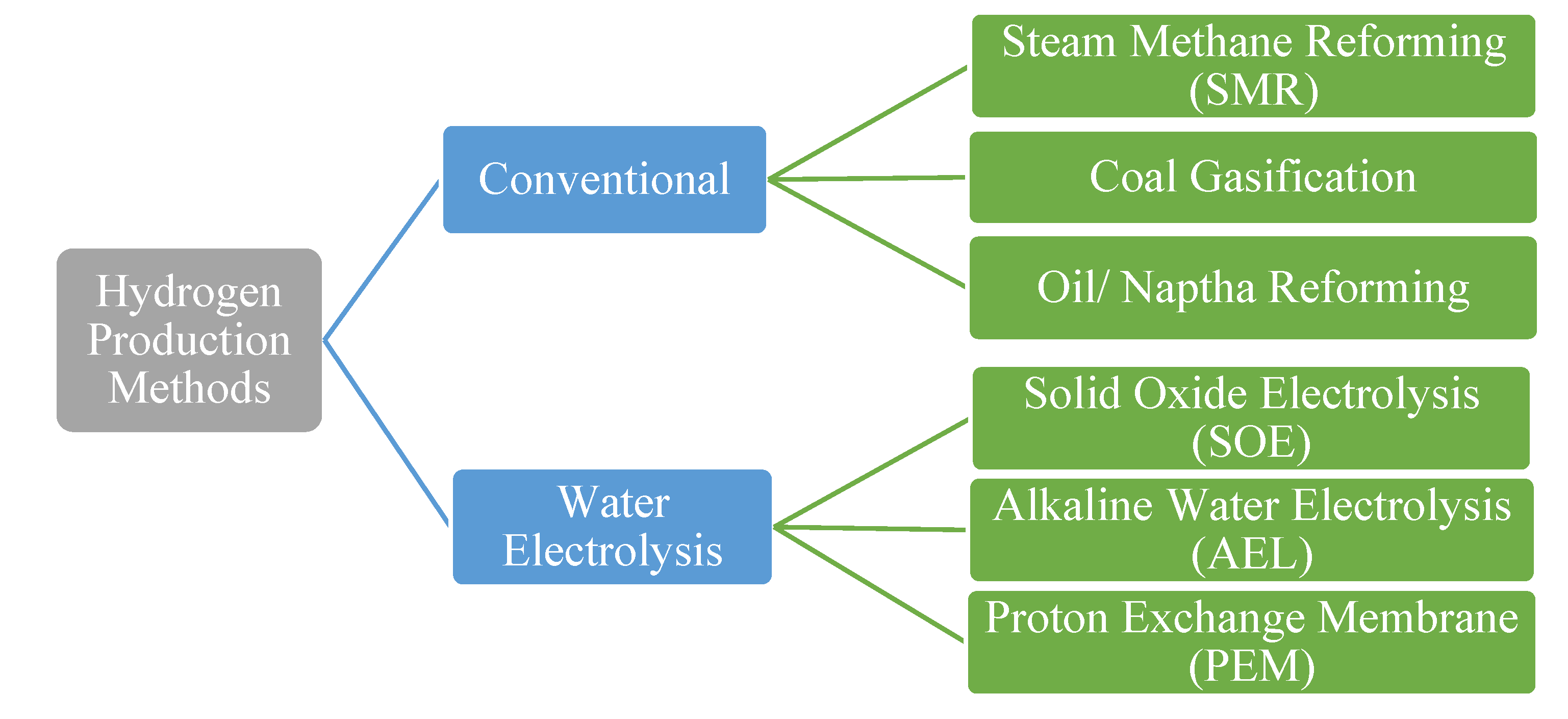
Hydrogen must be produced by some ‘clean and green source’ since the aim of this study is the mitigation of CO2 emissions. Hydrogen is mainly produced by conventional and renewable techniques. Several methods of hydrogen production are shown in Figure 1. Hydrogen produced by conventional processes utilizes fossil fuel energy in terms of coal, oil, and natural gas, and consequently emits huge amounts of CO2. The second method involves the utilization of renewable energy (RE) for hydrogen production [24]. The water electrolysis process for hydrogen production uses RE. The main challenge in the production of hydrogen by water electrolysis is the economics of the process.
The electrolysis of water needs energy for splitting water into hydrogen and oxygen. Energy is supplied to water in terms of thermal and electrical energy. Worldwide, electrolysis of water contributes only a 4% share of total hydrogen production while the remainder of hydrogen production still relies on conventional sources [25]. The contribution of water electrolysis is less due to its high production cost for hydrogen compared to conventional sources. The main challenges in water electrolysis include maintenance, minimization of energy consumption, increasing durability and safety [26]. The hydrogen produced by water electrolysis techniques is highly pure and can directly be supplied for utilization in some cases [27]. The purity of the hydrogen gas produced depends upon the nature of the electrolysis technique used. In this work, hydrogen is produced using water electrolysis techniques and then used as a feed stock for methanol production utilizing captured CO2. The methanol produced using hydrogen from water electrolysis is finally converted into DME by a dehydration reaction.
The most well-known green hydrogen production technologies based on water electrolysis are alkaline water electrolysis (AEL), proton exchange membrane (PEM) and solid oxide electrolyzer (SOE) [14]. AEL and PEM are low temperature technologies, while SOE is a high temperature method for producing hydrogen from water electrolysis. AEL and PEM have an operating temperature range of 60–95 °C while SOE operates at around 800 °C. AEL and PEM are mature technologies compared to SOE. The main challenge associated with SOE is the selection of material, but this technology seems to have future potential due to its improved economic feasibility [27]. The major difference in these processes lies in terms of thermodynamics since the operating temperature of SOE is high as compared to AEL and PEM so it requires less use of electricity. In past few years, hydrogen as a fuel has been revolutionized due to its negligible emissions and its production from REs [26].
AEL is the most mature technique for hydrogen production. It uses an alkaline solution (35% KOH) as the electrolyte and electricity is supplied for the electrolysis. The water electrolysis reaction occurs in the stack to produce gaseous hydrogen and oxygen. Hydrogen is produced at the cathode while oxygen is produced at the anode. The reversible cell potential is determined through the Nernst equation, which predicts the minimum electrical potential required for the electrolysis of water at a particular location in the cell with a specific temperature and gas concentration. The Nernst voltage is calculated using the Gibbs free energy by the following relation.
U r e v = Δ G   z F
Here, F is the Faraday’s constant, and its value is 96,485 C/mol and z = 2 i.e., two electrons are transferred in the electrolysis process of water. ∆G is the Gibb’s free energy of the reaction in kJ/mol [27]. Hence,
Δ G = Δ H T Δ S
Here, Δ H is the total energy demand, Δ G is the electrical energy demand and T Δ S represents the thermal energy demand. If the thermal energy is supplied to the system, the electrical energy requirements will decrease; i.e., if the electrolysis occurs at high temperature as in SOE, the total electricity requirement is reduced [19]. The actual voltage required for the cell is greater than the reversible voltage due to the irreversibility in the system [27].
Jingang et al. [28] reported that among hydrogen production methods including biogas steam reforming, fluidized bed biomass steam gasification and AEL, AEL has highest efficiency (i.e., 66%). The investment cost of AEL is less compared to other technologies but operating cost is high. Schmidt et al. [29] compared AEL, SOE and PEM based on the different operating conditions, costs and life-cycles. The comparison was based on previous literature. It was reported that the capital cost of AEL was the least while that for SOE was greatest. In another study, Christian et al. [25] reported AEL to be an environmentally friendly technique if the source is REs while AEL presented maximum environmental impact if coal was used for power production instead of REs. Sanchez et. el [30] made an experimental setup for AEL as well as simulating the AEL process. It was reported that the stack of AEL consumed 92% of the power and the stack power was the highest contributing factor in the overall cost of AEL.
PEM is termed as ‘polymer exchange membrane’ since it is made of polymeric membranes as electrolyte. In PEM, the membrane lies between the electrodes [28]. PEM is a mature technique and has gained much attention in the previous years due to its high performance. The hydrogen produced using this technology is clean since it has no CO2 or other GHGs emission, if a carbon free source of electricity is used. The membrane of PEM operates at a temperature of almost 70–80 °C [28]. PEM uses a relatively thin membrane. The membrane splits the water and, since it is proton conducting, it only allows the proton or hydrogen ions to pass through [29]. The investment cost of PEM is high as highly expensive materials such as platinum, titanium and iridium are used [31]. The thickness of PEM is only 0.2 mm [32]. The membranes of PEM must have high ionic conductivity, excellent chemical stability, mechanical strength and be relatively less expensive [28]. The electrolysis of water demands a higher voltage, while PEM has typical cell voltages ranging from 1.5 V to 2 V [31].
Julio et al. [33] reported that although the investment cost of PEM is high compared to other technologies, it can operate with high efficiency in MW ranges, unlike AEL which usually operates in kW ranges. Ibrahim et al. [34] mentioned that Nafion® has excellent properties and chemical stability. The main challenge is to maintain the humidification level inside the membranes which may deteriorate the membrane if it is not sufficient, and the chemical degradation of membrane might occur. A comparison was made between different membranes used for PEM such as Nafion® (Solution Technology Inc., Mendenhall, PA), organic and inorganic membranes and non-fluorinated membranes. It was reported that Nafion® membranes with fillers were the best.
Methanol and DME are among the best fossil fuel alternatives for the abatement of CO2 considering the global concerns over GHG emissions. Lonis et al. [18] simulated the production of methanol using both AEL and SOE based hydrogen production processes in Aspen Plus®. The efficiency of the AEL based process was less as compared to the SOE based process, since AEL required more power. Moreover, it was also reported that the capital cost of SOE was higher than AEL. Hydrogen production using different water electrolysis methods is considered clean, if a carbon free energy source is used. However, mostly experimental work is done on water electrolysis techniques and very limited simulation work is available on their detailed thermodynamic and economic performance. These water electrolysis techniques are usually compared based on experimental results in terms of capital cost and operating parameters such as temperature, pressure, voltages and current densities. Detailed thermodynamic and economic analysis of the water electrolyzed hydrogen production processes is required to evaluate and compare the performance using different hydrogen production methods.
This study has some significant features such as attempting to cover the research gap by presenting different routes for DME and methanol production from CO2 and hydrogen. In this study, hydrogenation of CO2 to methanol was integrated with a methanol dehydration plant for DME production. Instead of conventional processes of hydrogen production such as steam methane reforming, coal gasification and oil reforming that release CO2 into the environment, the hydrogen used is produced by clean technology, i.e., water electrolysis that utilizes REs to disassociate water molecules. The CO2 captured from a cement plant was used for hydrogenation to methanol. This process has two advantages, firstly it utilizes the captured CO2 that would be otherwise released into the environment and, secondly, hydrogen is produced by water electrolysis instead of conventional processes; hence, this process prevents the further release of CO2 into the environment. The methanol and DME can be used as gasoline substitutes; less hazardous emissions are expected from methanol and DME because they do not have nitrogen and sulfur compounds associated with them as compared to conventional fuels. Hence, the environment can be saved from further emissions of CO2 and pollution to some extent, by implementing this technique.
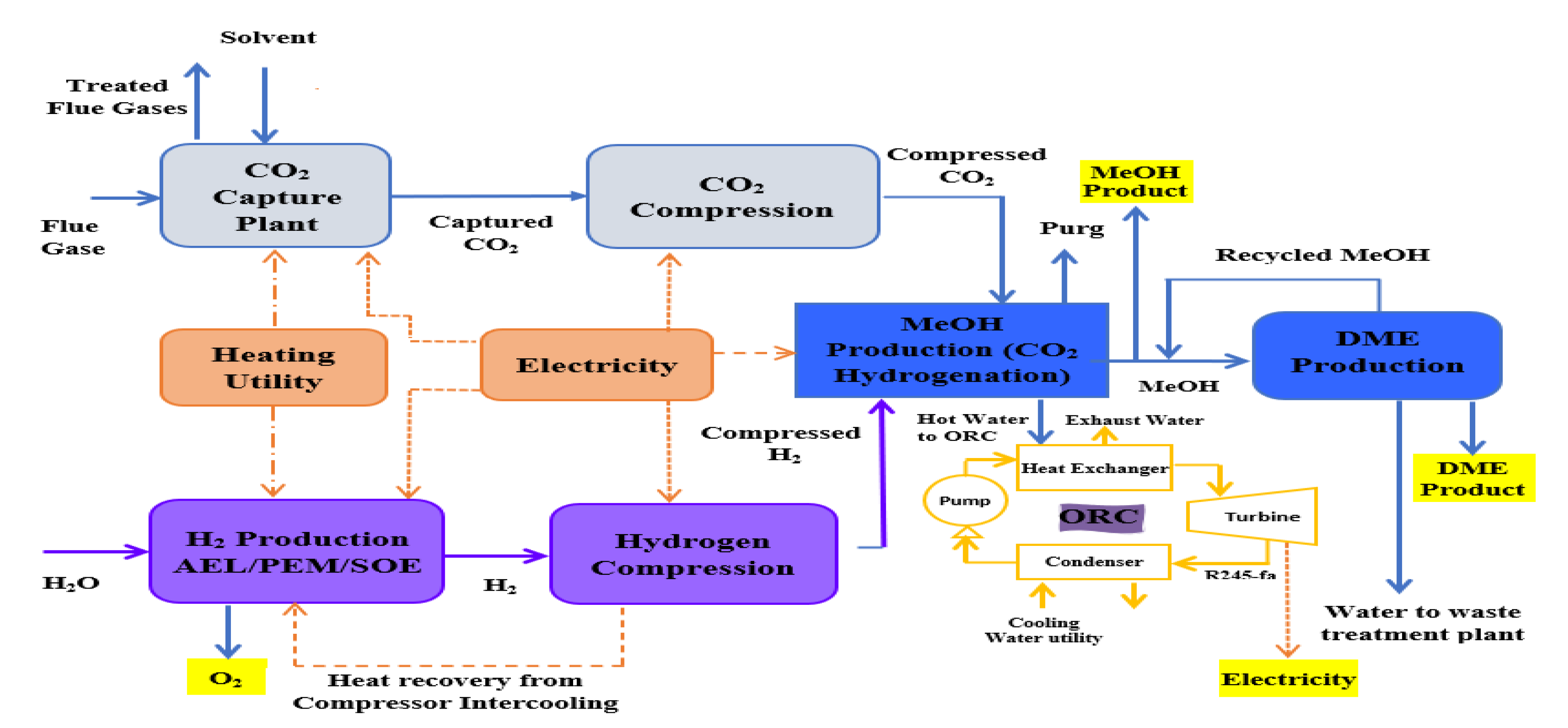
In this work, an integrated process is proposed to produce methanol and DME by using hydrogen from water electrolysis and CO2 from a post-combustion capture plant. The schematic of the proposed integrated process is presented in Figure 2. Simulations of the CO2 capture process are not performed in this study since extensive data are available on it. The captured CO2 from a cement plant was used in this study. The captured CO2 was compressed and sent to methanol production. Hydrogen produced by electrolysis of water, i.e., AEL, PEM or SOE was fed to the compression unit. The energy for compressors was provided externally. The compressed hydrogen was then fed to the methanol production unit. The amount of hydrogen produced by each water electrolysis process was the same. The thermo-economic comparison of methanol and DME integrated processes employing three different hydrogen production processes was performed in this work. The simulation flow sheets and the results of the SOE method for hydrogen production were taken from the work of Yousaf et al. [19]. This work is the extension of the published results of Yousaf et al. [19], where methanol production is simulated using hydrogen from SOE. In the already published results of Yousaf et al. [18], hydrogen produced by SOE was integrated with methanol production. However, the temperature of SOE is almost 800°C for electrolysis and the materials needed for SOE operation are still under research as they need to tolerate a high temperature. In the present study, the low temperature technologies (below 100 °C) such as AEL and PEM are used for simulation of hydrogen production. The AEL and PEM water electrolysis processes were modelled and integrated with the methanol production process to assess the technological and economic impacts of these processes on methanol production. The methanol flowsheet is used with some slight modification in the feed stream of hydrogen and then methanol was converted into DME to assess another PtL process for CO2 mitigation. Process flow sheets for hydrogen production were simulated using Aspen Plus® V11. The economic analysis was carried out using model equations and the Aspen Process Economic Analyzer® V11 (APEA).
In this work, water electrolyzed hydrogen production techniques, i.e., AEL and PEM, were simulated in Aspen Plus® and compared with the SOE [19]. The simulated water electrolyzed processes were compared to verify their economic feasibility in terms of total annual cost (TAC), power and cost per ton of hydrogen. The hydrogen production methods integrated with methanol production are compared in terms of TAC, cost per ton of methanol and cost per ton of methanol after selling oxygen. The methanol produced by the water electrolysis process is converted to DME and the cost per ton of DME is evaluated. The net emissions of CO2 by each integrated process are also assessed. The comparison shows that the cost for hydrogen production by AEL is the highest, and by SOE is lowest. Similarly, the cost of methanol and DME production is highest for AEL, and lowest for SOE. PEM has the highest power consumption among these three techniques, which may lead to high net emissions of CO2 if non-renewal energy is used.
2. Process Description

Hydrogen produced by the electrolysis of water using AEL and PEM was integrated with methanol production to assess the overall process economics for the hydrogenation of CO2. The methanol is then converted to DME. The three cases are discussed in this section along with the key operating parameters. The amount of hydrogen, methanol and DME produced in all the three cases is same for purposes of comparison. Brief details of these three cases are given in Table 1.

2.1. Case—I: Hydrogen Production Processes

This section presents the process description of AEL, PEM and SOE for the production of hydrogen.

2.1.1. Alkaline Water Electrolysis

AEL is a mature technique for hydrogen production using 35% alkaline KOH solution as an electrolyte. Electrical energy was supplied for the electrolysis to occur. The heated alkaline electrolyte along with water was pumped in the electrolyzer stack. The stack has cathode and anode. Water enters in the cathode side and reduction occurs, while H2 gas is produced along with hydroxyl ions. The hydroxide ions enter the anode side and oxidation occurs with the production of oxygen gas. The gases along with unreacted water and KOH electrolyte enter into the gas separators. In the gas separator, pure gases i.e., hydrogen and oxygen are separated, while the unreacted water and KOH are removed [27]. The hydrogen produced by AEL is sent to the methanol plant for CO2 hydrogenation into methanol.
The following reactions occur in AEL.
Cathode: 2H2O (l) + 2e → H2 (g) +2OH(aq)
Anode: 2OH(aq) → 0.5O2 (g) +H2O (l) +2e
Overall: H2O (l) → H2 + 0.5O2 (g)
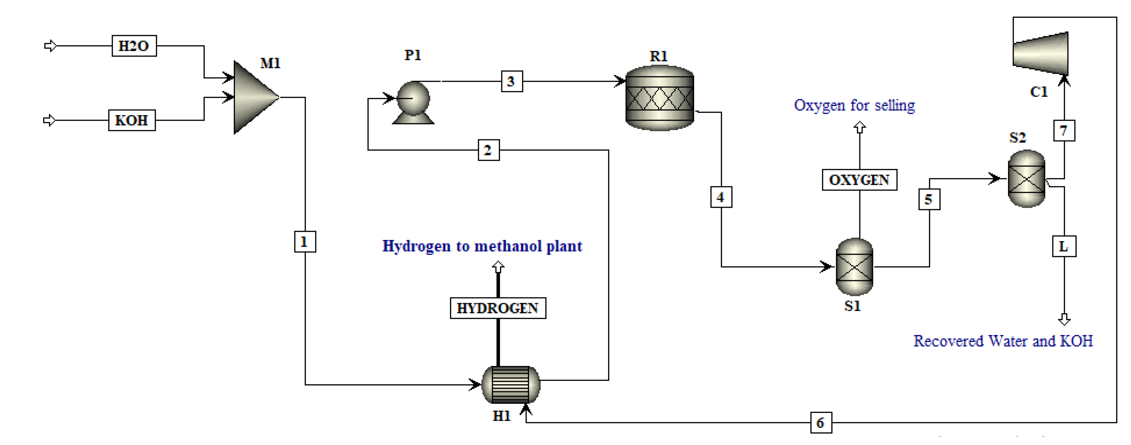
Aspen Plus® has no built-in model to cater to the electrolysis reaction, so Francesco et al. [18] proposed that instead of doing rigorous modeling and complex calculations in Aspen Custom Modeler® (ACM), the AEL stack can be modeled as a combination of Reactor (RStoic) and Separator, as shown in Figure 3 [18].
The property package selected for the proposed electrolysis was NRTL. Water enters the mixer (M1) at a flow rate of 675 kg/hr at 25 °C and pressure of 1 bar [18]. An electrolyte of 35% KOH at 25 °C and 1 bar with a flow rate of 236.25 kg/hr also enters the mixer (M1). Both these streams are mixed and the mixed stream enters the heater (HEAT1), where the temperature of the feed stream is brought equal to the operating temperature of AEL i.e., 75 °C. Low pressure steam is provided as a utility to the heater. The heated stream enters into the pump (P1), where this is bought close to the operating pressure of AEL, i.e., 2.5 MPa. The pressurized feed stream exiting the pump enters the stoichiometric reactor (R1), where the reactions of water electrolysis occur producing oxygen and hydrogen.
The fractional conversion of water is taken to be99.9%in this reactor [18]. The product stream from the reactor has hydrogen, oxygen, some unreacted water, and KOH. Separators are used to separate the desired components. In the first separator (S1), oxygen is separated with a mass flow rate of 598.87 kg/hr [18]. The bottom stream (L1) from S1 has hydrogen and unreacted water and KOH. The second separator (S2) is used to separate hydrogen from unreacted feed. The top exiting stream is pure hydrogen with a mass flow rate of 75.45 kg/hr [18], while the bottom stream is unreacted water and KOH. The exiting hydrogen from the AEL plant is then integrated with methanol production and the pure oxygen is sent to its selling point.

2.1.2. Proton Exchange Membrane

Water enters at the anode side where its molecule splits into hydrogen ion, oxygen ion and electrons. Here oxygen gas is produced in the oxidation reaction. The membrane is proton conducting so it allows hydrogen ions to pass through it. The hydrogen ion after crossing the membrane enters the cathode where the reduction occurs and hydrogen gas is produced [29]. The following reactions occur in PEM.
Overall: H2O → 0.5O2 + H2
Anode: H2O → 0.5O2 + 2H+ + 2e
Cathode: H+ + 2e → H2
PEM is mainly divided into three portions; named as stack, cathode, and anode. The stack is the main component of PEM, where the main reaction of water occurs producing the desired hydrogen. The stack is the combination of a reactor and a separator. The cathode section is the part of PEM where hydrogen gas is produced while the anodic section produces oxygen gas.
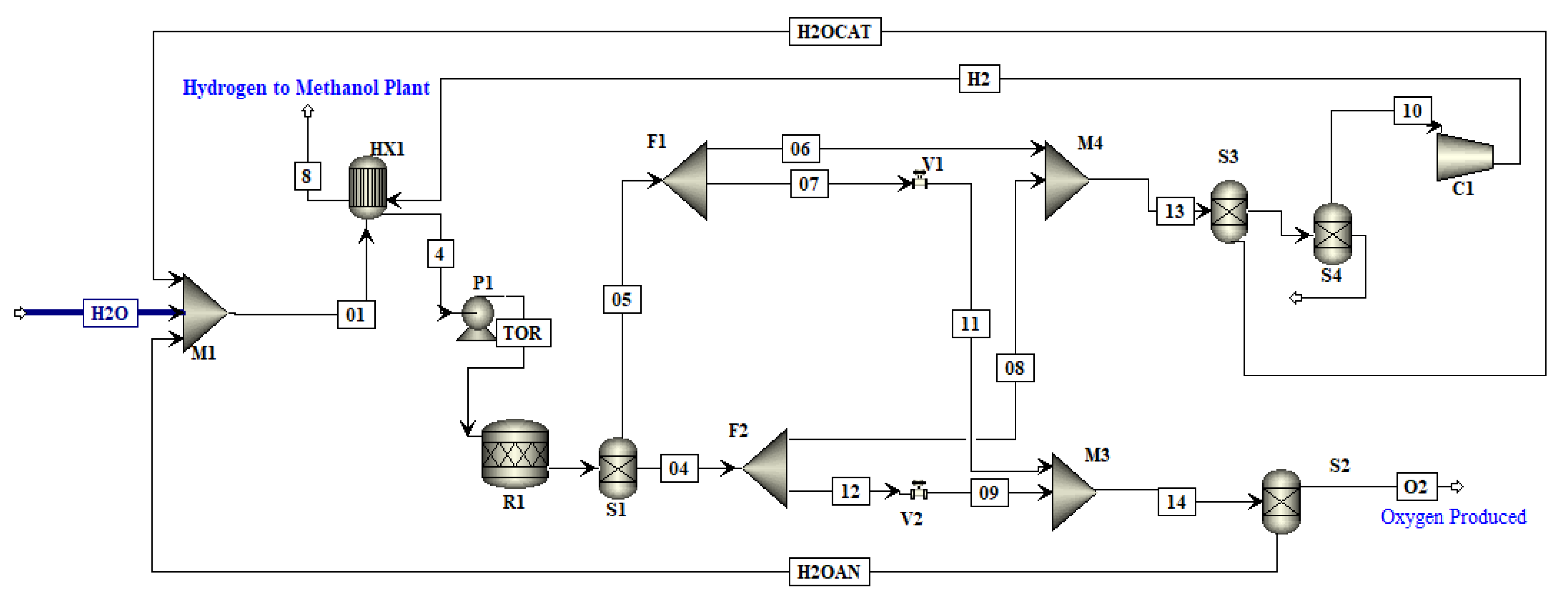
The flowsheet of PEM developed in Aspen Plus® is shown in Figure 4 [32]. Here the mixer is employed to mix the recycled streams of water from the cathode and anode sections with the freshwater feed. The mixed water (stream 1) is heated to almost 80 °C in a heater (HEAT 1). Then the heated water (stream 2) is pumped to provide sufficient pressure (i.e., 2.5 MPa) for the electrolysis reaction in PEM. The pumped feed water (stream 3) enters the reactor (R1) where the electrolysis reaction of water occurs.
The exit stream (stream 4) of R1 is the gaseous hydrogen, oxygen and some amount of unreacted water. Stream 4 enters a separator (S1) to separate the streams of hydrogen and oxygen product. The separator (S1) removes hydrogen (stream 5) as the top stream while the bottom stream (stream 13) is mostly oxygen and water. The bottom stream enters a divider (D2) and it is divided into two streams. The upper stream (stream 15) is only 1% of the total stream and it has mainly oxygen in it. Stream 15 is sent to the hydrogen chamber. The oxygen (stream 15) reacts with hydrogen and produces water so it can be recycled. In the same way, 1% by weight of stream 5 from the hydrogen section (i.e., stream 7) is sent to the oxygen section to react with oxygen and produce water to recycle that for electrolysis. The stream from the mixer (M3) enters a separator (S2) to separate the water from oxygen. The recovered water is recycled for electrolysis in mixer (M1). In S3, water is removed from hydrogen, and is sent to the mixer (M1) to mix with the incoming feed of fresh water. The stream from the bottom of separator (S3) is hydrogen and oxygen. This stream again enters the separator (S4) to separate hydrogen and oxygen. The oxygen gas is removed from the bottom of separator (S4) while hydrogen gas removed from the top enters the compressor (C1) to compress the hydrogen. The hydrogen produced by PEM is sent to the methanol production plant as shown in Figure 4.

2.1.3. Solid Oxide Electrolyzer

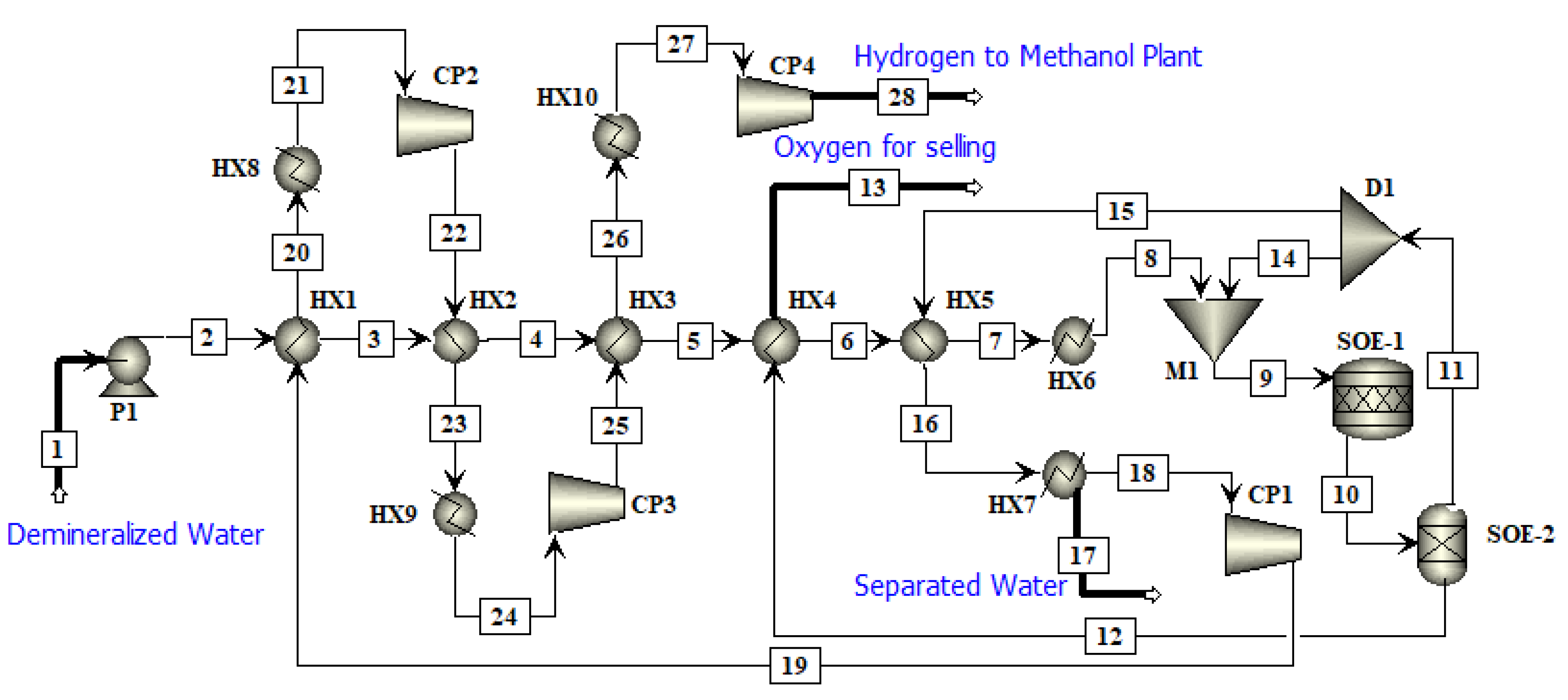
The SOE hydrogen production and compression process was not simulated in this work as it was simulated previously by Yousaf et al. [19] and the detailed flowsheet as well as the results are taken from this previous work [19]. The flowsheet of the SOE process is shown in Figure 5. Demineralized water was pressurized to 2 bar in the pump (P1) and was preheated to 800 °C in a series of six heat exchangers (HX1, HX2, HX3, HX4, HX5 and HX6) to produce superheated steam. In HX1, HX2 and HX3 heat from compressors intercooling was used to preheat the water. Oxygen and hydrogen leaving the SOE were used as a heating source in HX4 and HX5, respectively. Finally, high pressure steam was employed as the heating utility in HX6 to meet the operating requirements. A further description of SOE based hydrogen production can be seen from the previous work [19].

2.2. Case—II: Methanol Production Processes

The methanol production process has three sub-categories i.e., AEL-Methanol, PEM-Methanol and SOE-Methanol production processes, as shown in Table 1. The methanol flowsheet is taken from the previous work of Yousaf et al. [19]. The only difference in these three sub-categories is in the production of hydrogen i.e., AEL, PEM and SOE. The finalized flow sheets for AEL and PEM based hydrogen production are given in Appendix A. A brief description of the methanol production process is included in this section.
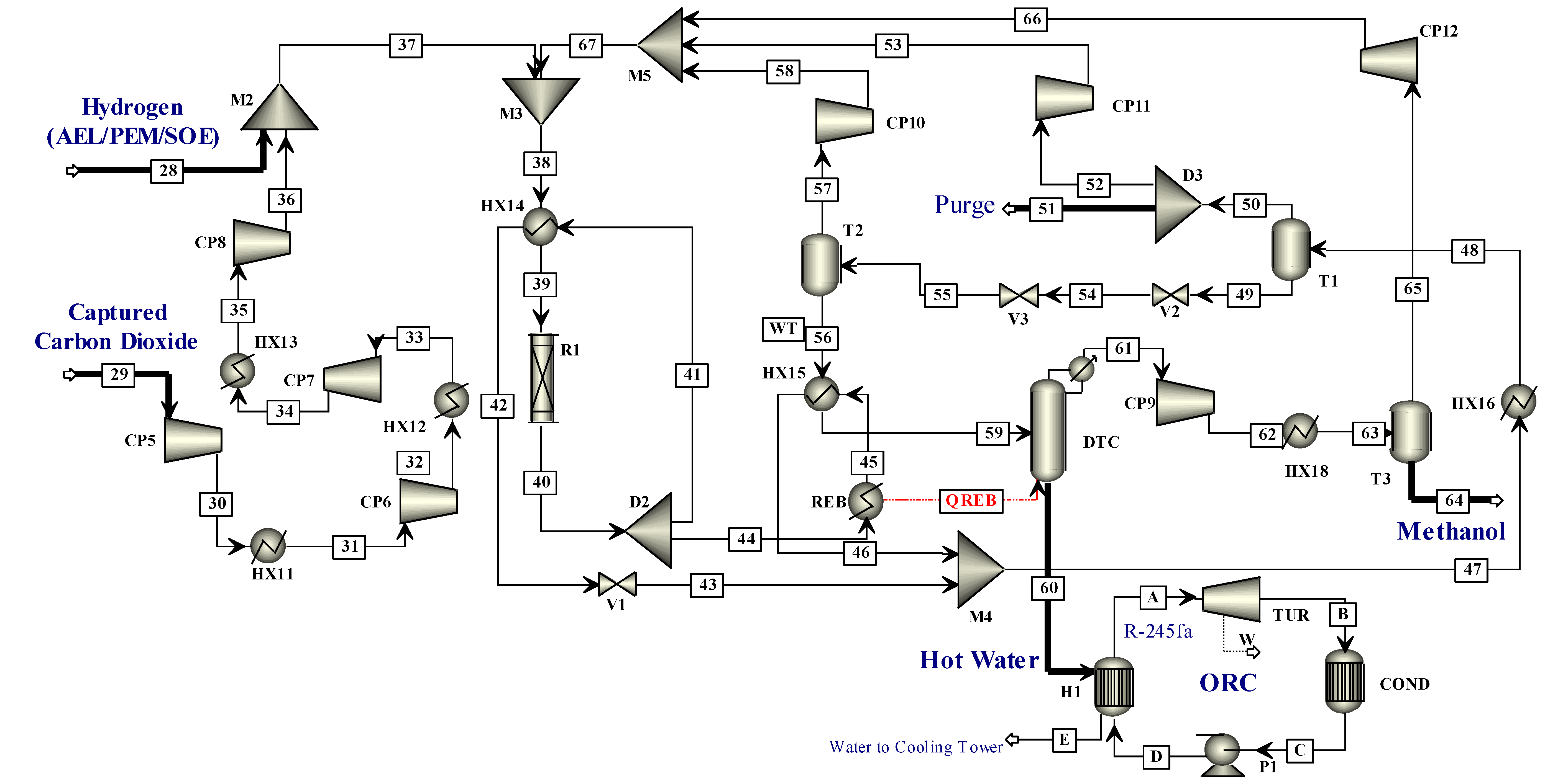
CO2 (at 2 bar and 28 °C) was compressed to 78 bar, while hydrogen was fed at 78 bar and 184 °C for AEL and 78 bar and 129 °C for PEM (see Figure 6), while hydrogen was fed at 78 bar and 192 °C for SOE [19]. The feedstock for methanol was mixed with the recycled stream and was heated in HX14 using the heat from reactor outlet stream and fed to the fixed bed adiabatic reactor packed with commercial Cu/ZnO/Al2O3 catalyst. The crude methanol stream exiting from the reactor at a high temperature can be used for heating, so is divided into two streams. The divided streams after preheating were mixed, cooled to 35 °C and fed to a series of flash tanks to remove untreated gases from the water-methanol mixture. The liquid stream leaving the first flash tank was at a high pressure of 73 bar, so expanded to 1.2 bar in two valves. A small portion (about 1%) of the untreated gases was purged to the atmosphere to reduce the accumulation of inert gases in the system, and the remaining 99% unreacted gases were compressed to 78 bar and recycled back. The crude methanol leaving the second flash tank was heated and sent to the distillation column to separate the methanol and water. The water withdrawn from the bottom of the column at 102 °C (stream 60) with a flow rate of almost 35,000 kg/hr can be used as a waste heat recovery in an organic Rankine cycle (ORC). The refrigerant R-245fa is used with a flow rate of 3600 kg/s. Methanol obtained from the top at 1 bar and 64.1 °C containing minor impurities was compressed to 1.2 bar and cooled to 40 °C. This methanol was then fed to a flash tank, and the unreacted gases were recycled back. The final product obtained in liquid form is 99.5% pure methanol.

2.3. Case—III: Dimethyl Ether Production Process

Since DME is produced by the dehydration reaction of methanol, the methanol product stream coming from the methanol plant is used to produce DME as given in Equation (13).
2CH3OH → H2O + CH3-O-CH3
The complete process of DME production using the methanol from CO2 hydrogenation was simulated in Aspen Plus® and is presented in Figure 7 The purity of methanol from the methanol plant is more than 99% while less than 1% are impurities such as water and unreacted gases, which are separated from the methanol. Pure methanol at 1 bar and 40 °C is sent to the DME plant. The feed passes through pump (P1) which imparts a pressure of 15 bar to achieve the conditions for the methanol dehydration reaction. The pressurized methanol (stream 1) enters the mixer (M1) where it is mixed with the recycle stream (RECYCLE) of methanol at 137 °C and 15 bar. The mixed (stream 2) at 15 bar and 64 °C enters the heat exchanger (HE1) where it is preheated to 250 °C by the product stream (stream 4) coming from the reactor. The heated feed stream (stream 3) enters the reactor (R1) where the dehydration reaction of methanol occurs, producing water and DME, as presented by Equation (13). The temperature of the dehydration reaction is 350 °C and pressure is 15 bar. The overall conversion of methanol to DME is 80% in the reactor. The exiting stream from the reactor is 40% water, 19% methanol and 39% DME. The product stream (stream 4), being at a high temperature of 350 °C, is used to pre-heat the feed stream in a heat exchanger (HE1). The product stream (stream 5) after pre-heating the feed stream exits the heat exchanger at 14 bar and 150 °C. This stream is cooled in the cooler to a temperature of 90 °C before entering a distillation column (DTC1) to purify the DME. The first distillation column (DTC1), having 22 stages, recovers the DME. Pure DME (99.99%) is removed from the top of the first column at a temperature and pressure of 61 °C and 15 bar, respectively. The bottom product (stream 7) of the DTC1, i.e., 67% water and 33% methanol is sent to the second distillation column (DTC2) to separate the water and methanol. The DTC2 has 15 stages and methanol is removed from the top (stream recycle) at 137 °C and 10 bar with a purity of 95%. This methanol is recycled back in the Mixer (M1) while the water removed from the bottom of DTC2 is at 180 °C and 10 bar. This water having some traces of methanol and DME is sent to the wastewater treatment plant to recover pure water.

3. Simulation Strategy

The hydrogen production process by AEL was simulated using the concept presented by Francesco et al. [18] and PEM was simulated using the concept presented by Zaccarra et al. [32]. Hydrogen production by SOE and methanol production processes were taken from published results of Yousaf et al. [19]. The detailed feed conditions, models and property packages used in the simulations are provided in the following paragraphs.

3.1. Feed Conditions

The feed streams to the hydrogen production process using AEL were water and 35% KOH solution at 25 °C [18] while for PEM water at 25 °C was used. The feeds for the methanol production process were hydrogen produced by water electrolysis (i.e., AEL and PEM) and CO2. For the AEL-Methanol integrated process, hydrogen was fed to the methanol plant at 184 °C and 78 bar while for PEM-Methanol the conditions were 129 °C and 78 bar. CO2 (at 28 °C and 2 bar) was considered to be captured from the flue gas of a cement plant using an MEA based process [19]. Methanol produced from AEL/PEM/SOE is highly pure and this methanol product was used as feed for the DME process.

3.2. Selection of Models and Property Packages

Hydrogen production by water electrolysis is a complex process and its modelling is a tiresome task. Moreover, as already mentioned, Aspen Plus® cannot simulate electrolysis processes as it does not incorporate the motion of electrons. In this work, thermodynamic simulations of hydrogen production by water electrolysis were performed using a combination of ‘RStoic’ and ‘SEP’ models of Aspen Plus®. The thermodynamics of the process of water breakdown into hydrogen and oxygen are the same as that of water electrolysis. The thermodynamic parameters (i.e., ΔH and ΔS) obtained from Aspen Plus® were used to calculate the voltage and power required for this process. The details of the procedure for operating cost calculations are given in previous work [19].
The property package selected for both methanol and DME simulations was NRTL. The kinetics of the methanol production reaction over the given catalyst were given by Mignard et al. [35] and the kinetic parameters for the CO2 hydrogenation reaction are given in the published results of Yousaf et al. [19].

3.3. Economic Analysis

The aim of this study was to investigate the economic and technological impacts of: (1) hydrogen production methods using water electrolysis techniques, (2) conversion of hydrogen into methanol, and then (3) production of DME from methanol. In this study, APEA® was used to carry out the economic analysis of this process. The basic equations involved in the economic analysis and cost parameters used are presented in this section. APEA® yields the capital, raw material, utilities and operating costs of the overall process (except the electrolysis stack). Based on these costs, the per ton costs of hydrogen, methanol and DME were evaluated considering different electrolysis processes. The capital cost could be converted to annual capital cost (ACC) by using a capital recovery factor (CRF), as presented by Equation (14) and Equation (15), respectively.
A C C = C R F × C C a p i t a l  
where
C R F = n 1 + n j 1 + n j 1
where j is the interest rate and n is plant life. Their values can be found in Table 2.
For the integrated methanol production process, the overall capital cost is the sum of capital cost of electrolysis and the capital cost of the methanol production process, as presented by Equation (16).
C C a p , i n t   = C C a p ,   e l e c t r o l y s i s + C C a p , m e t h a n o l
Similarly, the overall operating cost of integrated process is the sum of cost of electricity required for electrolysis and all the other operating expenses (estimated using the APEA®) including the cost of raw materials, utilities cost, installation cost, equipment cost, labor cost etc., as presented by Equation (17).
C o p , t o t a l = C o p , e l e c t r i c i t y + C o p , o t h e r s
The prominent economic parameters used in this study along with their sources are mentioned in Table 2. These input parameters are used for the processes named as Case (hydrogen production), Case II (methanol production) and Case III (DME production) for evaluation of cost per ton (of hydrogen, methanol and DME) and TAC.

3.4. Carbon Dioxide Balance

CO2 abatement is performed in this study by converting CO2 into a useful product. CO2 hydrogenation is used to produce methanol and then methanol is converted to DME. The overall CO2 balance of the process includes the CO2 used for methanol production, CO2 emitted with the product and CO2 emitted in the utilities supporting the hydrogen, methanol and DME production processes. The electrical energy supplied for the electrolysis process can be from conventional sources (such as coal, oil or natural gas) or from REs, such as wind, solar or biomass. The CO2 emissions depend on the energy source and the emissions from different sources of energy were taken from the World Nuclear Association’s (WNA) report [41]. The overall CO2 balance can be represented by Equation (18). This analysis was performed to identify the source of energy that gives minimum emissions of CO2 per unit of methanol or DME produced, or maximum utilization of CO2. The net CO2 consumed per unit of DME from different sources is presented by Equation (18). Moreover, net CO2 consumed per unit of methanol from different sources can also be presented with a similar equation (i.e., Equation (18)) after removing C O 2 u t y   D M E term.
C O 2 c o n s u m e d = C O 2 i n C O 2 o u t C O 2 u t y   m e t h a n o l C O 2 u t y   D M E C O 2 u t y   e l e c t r o l y s i s

4. Results and Discussion

AEL and PEM models for hydrogen production developed in Aspen Plus® were validated with literature. A comparison based thermo-economic analysis of water electrolysis methods (i.e., Case I) along with integrated methanol (i.e., Case II) and DME production (i.e., Case III) processes was performed. Methanol production by CO2 hydrogenation is considered an economically infeasible process due to the high cost associated with hydrogen production. Some modifications were made in the published results from previous work of Yousaf et al. [19] when AEL and PEM were integrated with methanol production. The AEL and PEM integrated methanol processes were compared with SOE integrated methanol production, i.e., the recent work of Yousaf et al. [19]. Finally, the thermodynamic and economic analyses of the integrated DME production process (i.e., Case III) are presented in this section. Details of the mass and energy balance results are given in the Supplementary Materials.

4.1. Case I: Hydrogen Production

The simulations of hydrogen produced by water electrolysis (i.e., AEL and PEM) were verified by comparison with the literature. The hydrogen produced by AEL and PEM is also compared with SOE from the author’s previous work [19] for the same amount of hydrogen produced to find the most feasible and economic process for hydrogen production.

4.1.1. Validation of Hydrogen Production Results

Both AEL and PEM processes were simulated in Aspen Plus®. The results of these processes were validated against the published results using the same input parameters. The model results of AEL were compared with the model of Francesco et al. [18]. The input parameters for validating the AEL model were taken from Francesco et al. [18], i.e., the flowrate of inlet water (675 kg/hr at 25 °C), concentration of KOH (35%), temperature and pressure of the electrolysis process (75 °C and 25 bar) and the discharge pressure of the pump (25 bar). Zaccarra et al. [32] also simulated SOE and PEM in Aspen Plus® and then integrated these hydrogen production processes with methanol production. The model of PEM was developed based on the concept of Zaccarra et al. [32]. The results of the simulations in the current work for PEM are compared with the results of Zaccarra et al. [32] and presented in Table 3. The input parameters for PEM validation were taken from the published results of Zaccarra et al. [32], i.e., the flowrate of inlet water stream (97.8 kg/s), temperature and pressure of process (80 °C and 25 bar), the thickness of membrane (0.2 mm) and the operating conditions of equipment. Validation of the SOE process was already performed in the previous work [19].
Reasonable agreement can be seen between the current work and literature values as shown in Table 3 The maximum error for the AEL process is in the electronic efficiency which is 2.7%. This deviation may be due to the use of stack developed in ACM; the simulations in this work are done in Aspen Plus®, as these tools employ different models. Instead of the stack, a combination of reactor and separator is used for the electrolysis. The maximum deviation for the PEM process is in the power required, which is 3.8%. This difference may be due to the slight amount of H2, i.e., 2% hydrogen that goes with oxygen. To recover this 2% H2, additional equipment would need to be installed which increases the overall cost of the plant and is not economically feasible [32]. Hence, the loss of 2% H2 in the current simulation is not recovered. The power required may be due to the greater product purity required in this work, since pure H2 product is being removed that is free from H2O and O2.

4.1.2. Comparison of SOE, PEM and AEL

The economic analysis of AEL, SOE and PEM was performed using APEA®. The capital and operating cost were also calculated by APEA®. The interest rate was taken to be 8% and plant life was taken to be 20 years [42] for CRF. The Nafion® membrane used in PEM additionally contributes to the overall cost. The cost of Nafion® is $176/kg and the life of the Nafion® membrane is almost 11 years. The key performance parameters for hydrogen production processes (i.e., AEL, PEM, SOE) are compared in this section based on the same hydrogen production rate as presented in previous work [19].
The detailed comparison of the three processes is shown in Table 4. The amount of water required by each process was slightly different. The amount of hydrogen and oxygen produced through AEL, PEM and SOE was almost the same. The capital cost of the SOE was the highest since it uses a series of compressors and heat exchangers which increases its investment costs. The cost of utilities (cooling) was also greatest for SOE since several compressors intercooling is required which increases the utility cost. AOC is highest for AEL since the AEL uses additional raw material with water, i.e., KOH for electrolysis unlike SOE and PEM which only use water as a raw material. Stack area was greatest for AEL and least for SOE, as shown in Table 4.
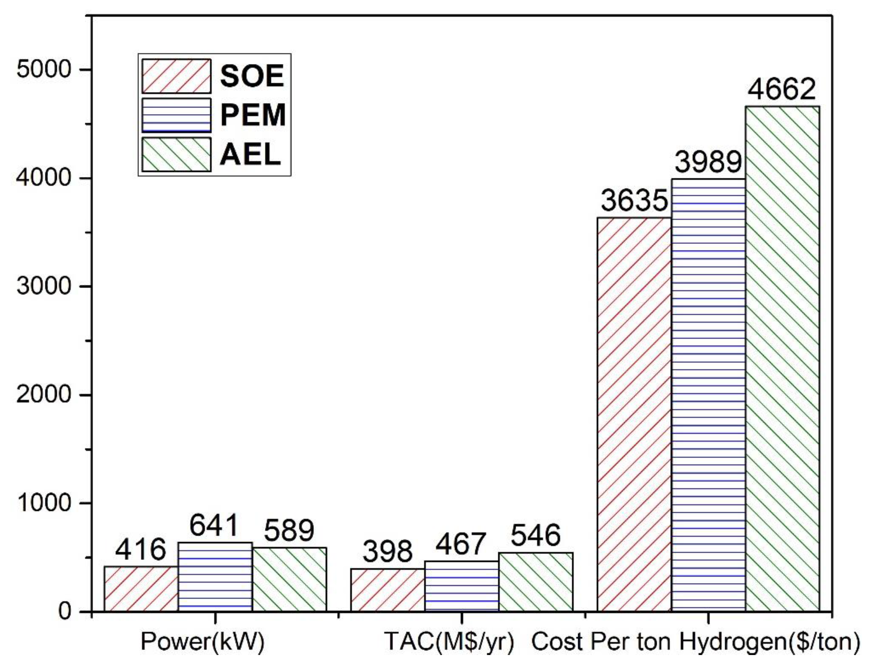
The key performance parameters including power required, TAC and cost per ton of hydrogen are also presented in Figure 8 The power requirement was 416 MW for SOE, 590 MW for AEL and 642 MW for PEM. The power requirement was highest for PEM and lowest for SOE. The highest power is required by PEM due to the use of membranes. In PEM, the membrane thickness is very low, i.e., 0.2 mm, to ensure the proximity of the electrodes. As the thickness decreases, the flux across membranes increases and the resistance inside the membrane decreases. Since current and resistance are inversely related, when decreasing the resistance, the required current increases which increases the total power required. The minimum power is required by SOE since it operates at a high temperature of 800 °C; as the thermal energy increases the electrical energy demand decreases. TAC is highest for AEL and lowest for SOE. The cost per ton of hydrogen ($/ton) is highest for AEL (i.e., $4662/ton) and lowest for SOE (i.e., $3635/ton). The cost per ton of hydrogen by PEM is slightly higher than that for SOE as shown in Figure 8 It should be noted that PEM is a relatively mature technology compared to SOE and its operating temperature is low to avoid any material limitations.

4.2. Case II: Methanol Production Process

In this section, the hydrogen production processes are integrated with methanol production processes and some key performance parameters are presented in this section. The results of the SOE integrated methanol process are taken from the published work of Yousaf et al. [19]. It has already been noted in the introduction section that the major cost burden for methanol production is the cost of hydrogen production. Therefore, the methanol production processes (i.e., AEL based methanol, PEM based methanol and SOE base methanol) will follow the cost trends of hydrogen production (i.e., AEL, PEM and SOE).
The same amount of hydrogen, i.e., 12,122 kg/hr producted by each of the electrolysis processes is intergrated with methanol production. The operating conditions of conveying hydrogen from water electrolysis into the methanol plant are different as mentioned earlier, whereas all other operating parameters are same. The integrated processes are compared and the economic analysis of methanol integrated with each electrolysis process is presented in Table 5.
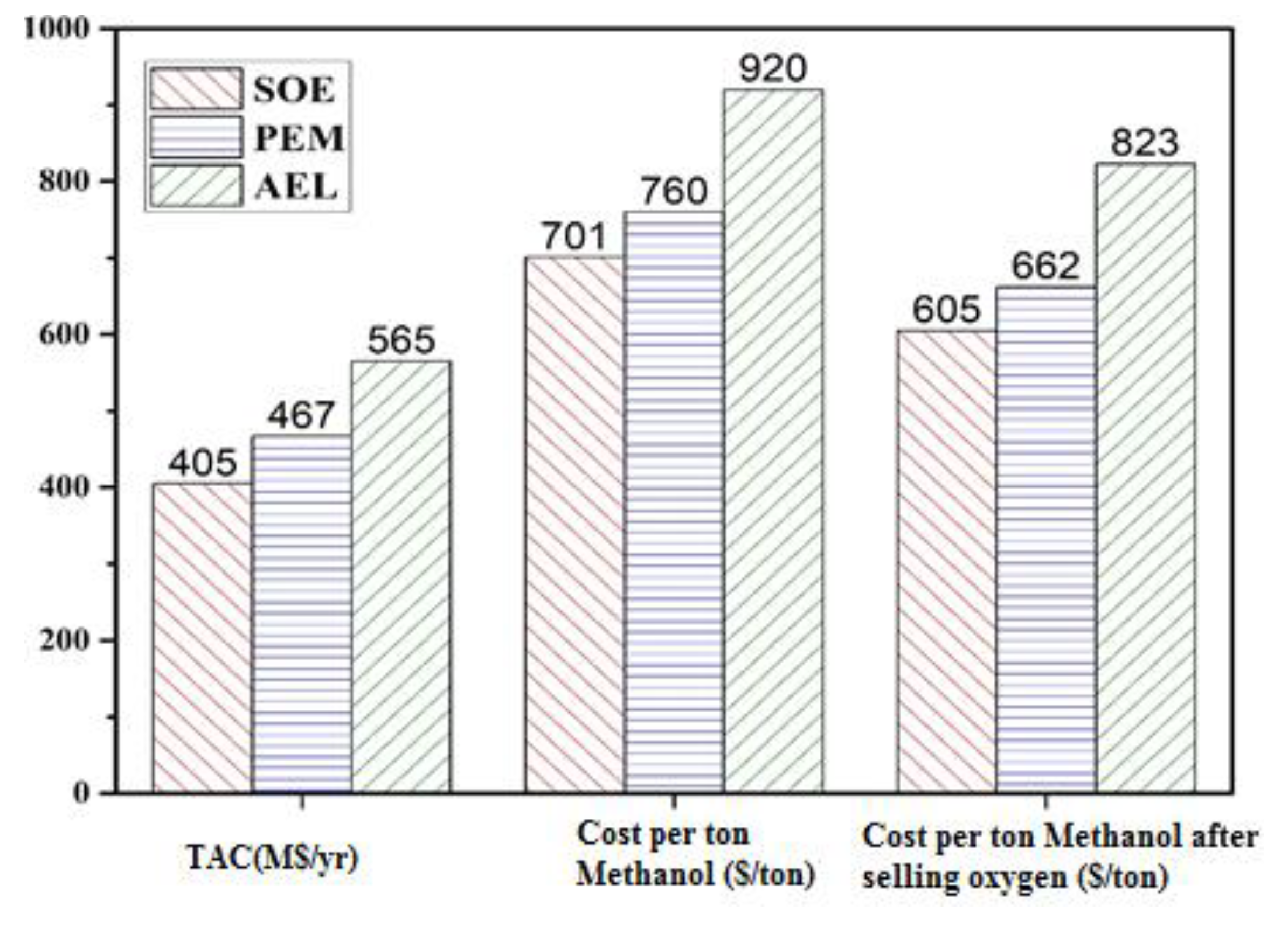
Figure 9 shows the comparison of three hydrogen production processes integrated with methanol production process. The TAC is highest for the AEL-methanol integrated process since it has high operating costs due to supplementary raw material used in the AEL process i.e., KOH. Although the capital cost of SOE is high due to a series of compressors and intercoolers, it operates at a high temperature of about 800 °C and requires less power which reduces the cost of electricity and ultimately the TAC is lowest for the SOE-methanol integrated process. The cost per ton of methanol is highest for AEL and lowest for SOE. AEL entails the highest expenses compared to SOE and PEM due to its high TAC. The cost per ton of methanol using AEL is compared with that mentioned in the literature [29]. i.e., $960/ton. The net cost per ton of methanol ($/ton) is calculated by subtracting the income from selling the oxygen produced by water electrolysis. The economic comparison shows that the SOE-integrated process for methanol production is economical compared to the other two processes. However, it can be concluded that PEM-integrated methanol production process can also be a good option in comparison to SOE-integrated methanol production process as it is a mature technique and selection of material or its stability is not major issue as compared to other options.
An ORC is employed to extract waste energy from the hot water stream, totalling 35,000 kg/hr at 102 °C (stream 60 in Figure 6.). The efficiency of the ORC is small (10%) as the source temperature is low. Electricity produced by ORC is only 24 kW which is negligible compared to the power requirements of AEL and PEM, i.e., 590 MW and 642 MW, respectively. This energy produced by ORC will contribute less than 0.005% in the electrolysis process and, therefore, this ORC energy is not used in these simulations.

4.3. Case III: Integrated Dimethyl Ether Production Process

DME is produced from methanol coming from the methanol production plant. Three integrated processes for the production of DME have been simulated including AEL-Methanol-DME, PEM-Methanol-DME and SOE-Methanol-DME. Each integrated process is capable of yielding the same amount of DME, i.e., 430,000 ton/yr. As the raw material for DME is methanol, the cost of methanol varies based on the type of electrolysis technique used. The cost of methanol produced by conventional processes ($542/ton) is much less than from the electrolysis process, i.e., $701/ton for SOE [19], 760 $/ton for PEM and $920/ton for AEL.
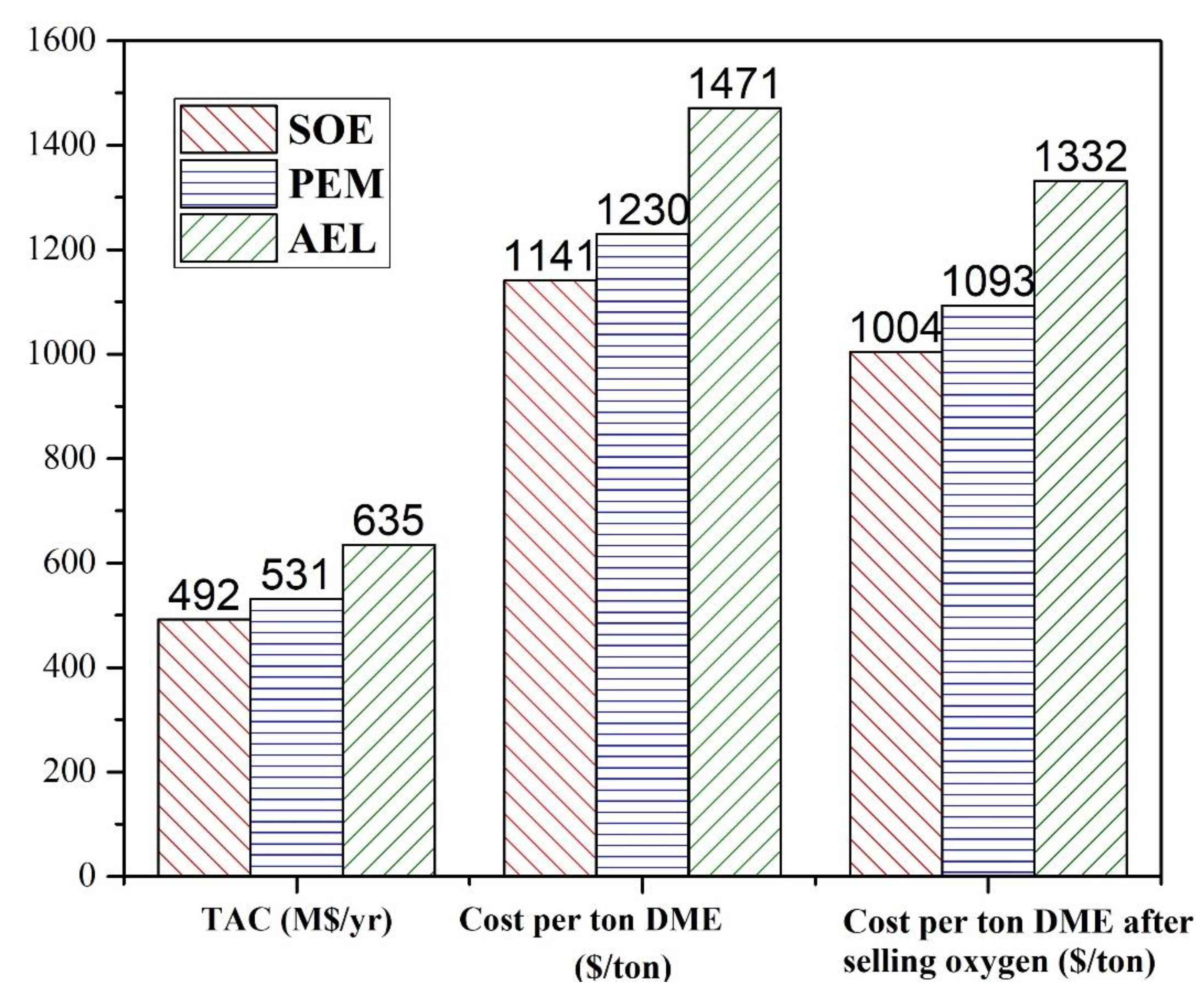
The economic analysis for three different DME processes (i.e., AEL-methanol-DME, PEM-methanol-DME, SOE-methanol-DME) is presented in Table 6. The input parameters for the DME process are the same for all cases as the same methanol feed is being used and the only difference is in the techniques for the production of hydrogen. If DME is produced using the methanol produced by some conventional processes that has CO2 emissions, the market cost of DME is at a minimum, i.e., $888/ton. For electrolysis process, AOC, TAC and cost per ton of DME are lowest for the SOE-Methanol-DME integrated process and highest for the AEL-Methanol-DME integrated process. However, AOC, TAC and cost per ton of DME for the PEM-Methanol-DME integrated process are around 8% higher than for the SOE-Methanol-DME integrated process. AOC, TAC and cost per ton of DME for AEL-Methanol-DME integrated process are around 30% higher than for the SOE-Methanol-DME integrated process. Cost per ton of DME is compared with the cost for a conventional process in Figure 10 Cost per ton of DME for SOE-Methanol-DME, PEM-Methanol-DME and AEL-Methanol-DEM is 28.5%, 38.5% and 65.6% higher than the cost per ton for a conventional process, respectively. The costs per ton of methanol and DME after selling oxygen for SOE-Methanol-DME, PEM-Methanol-DME and AEL-Methanol-DEM are calculated by deducting the market price of oxygen, i.e., $1004/ton DME, $1093/ton DME and $1332/ton DME, respectively. The detailed economics of the DME integrated process is shown in Figure 10.

4.4. Carbon Dioxide Balance

The net emissions of CO2 constitute an important parameter to determine the overall sustainability and feasibility of the process. Net emissions of CO2 are calculated using Equation (18). The CO2 emissions depend on the source of electricity and utility. In this study, net CO2 emissions mainly depend on the source of electricity used for compression and hydrogen production by water electrolysis. A comparison of CO2 balance for various energy sources used for AEL-Methanol-DME, PEM-Methanol-DME and SOE-Methanol-DME integrated processes is presented in Figure 11 and Figure 12.
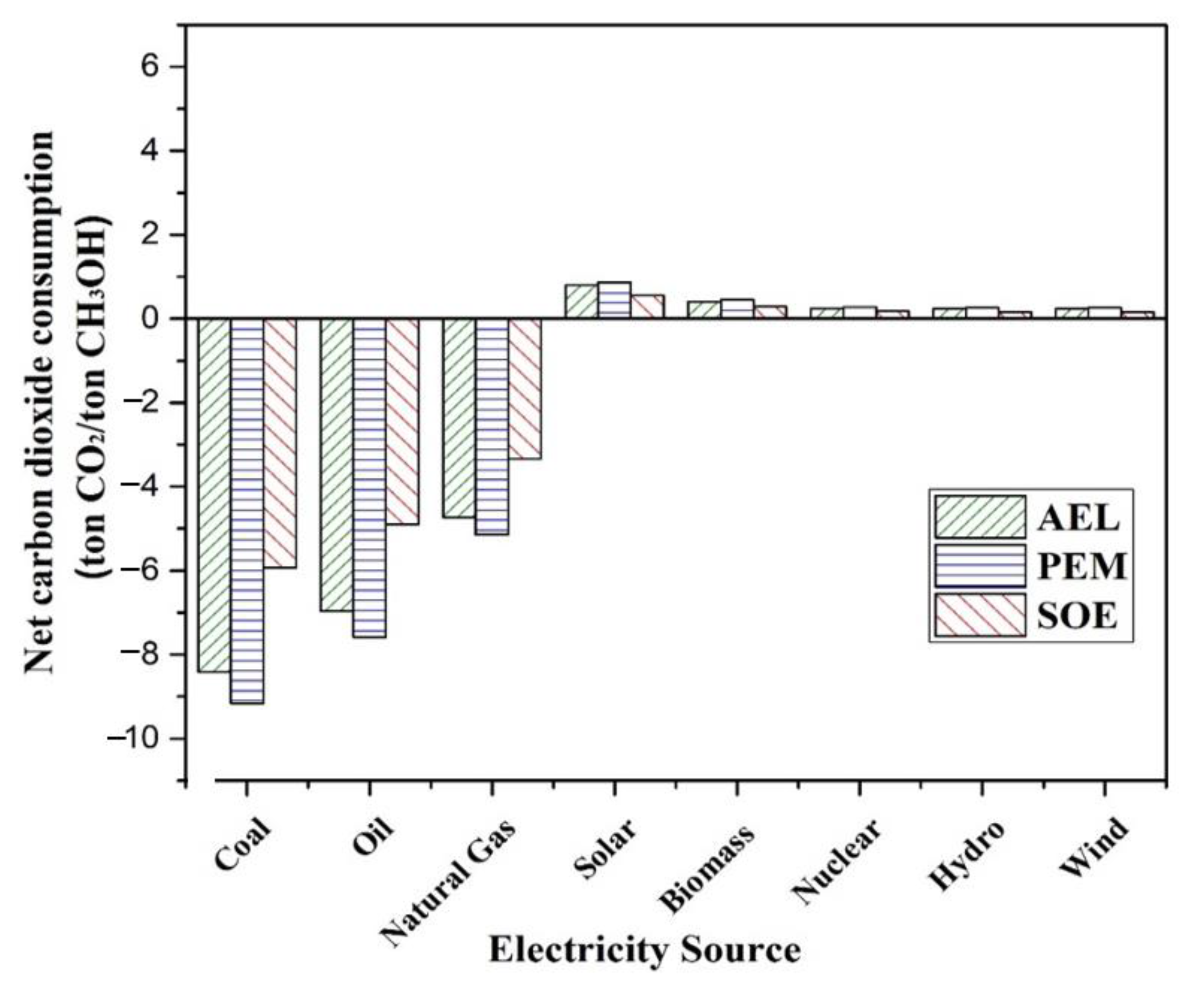
In Figure 11, the net consumption of CO2 for SOE-Methanol, PEM-Methanol and AEL-Methanol integrated processes is greatest for PEM as compared to SOE and AEL. Using the fossil fuel-based energy sources (i.e., coal, oil and natural gas) for AEL, PEM and SOE processes, net positive CO2 emissions were observed. Hence, the utilization of fossil fuel-based electricity sources should be avoided to maintain the sustainability of the process. Using renewable (e.g., wind, hydro, biomass and solar) and nuclear energy sources, the net CO2 was consumed. Among the REs, solar energy has the highest consumption of CO2 while the consumption of CO2 is almost the same using wind, hydro and nuclear energy in AEL, PEM and SOE.
The conventional process of methanol production i.e., steam methane reforming (SMR), emits 1.835 tons of CO2 for one ton of methanol production [43]. The market price of methanol from conventional SMR processes is $539/ton, where the cost of methanol by AEL-Methanol process is $920/ton and by the PEM-Methanol process is 760 $/ton. Referring to Figure 11., the highest CO2 utilization using REs, as solar energy, is 0.79 and 0.86 tons of CO2/ton of methanol for AEL and PEM, respectively. However, the methanol produced by the AEL process saves almost 2.6 tons of CO2 per ton of methanol, since 1.8 tons of CO2/ton of methanol emission are saved resulting from the SMR process in addition to 0.79 tons of CO2/ton of methanol saved from CO2 consumption by AEL based methanol production; this corresponds to additional expenses of $145/ton of CO2 mitigated from environment. The PEM methanol production avoids emissions of almost 2.7 tons of CO2/ton of methanol (1.8 tons of CO2/ton of methanol emission saved from SMR process and 0.86 tons of CO2/ton of methanol saved from PEM) with a supplementary charge of $82/ton of CO2 mitigated from the environment. For SOE, the total CO2 avoided per ton of methanol production was evaluated to be over 3.0 ton. This corresponds to around $57 additional expenses per ton of CO2 mitigated from the environment [19]. These expenses can be minimized by utilization of an economical source of energy to implement these processes on commercial scale since the cost of water electrolysis (i.e., electricity source) imposes a major cost burden in the overall methanol production process.
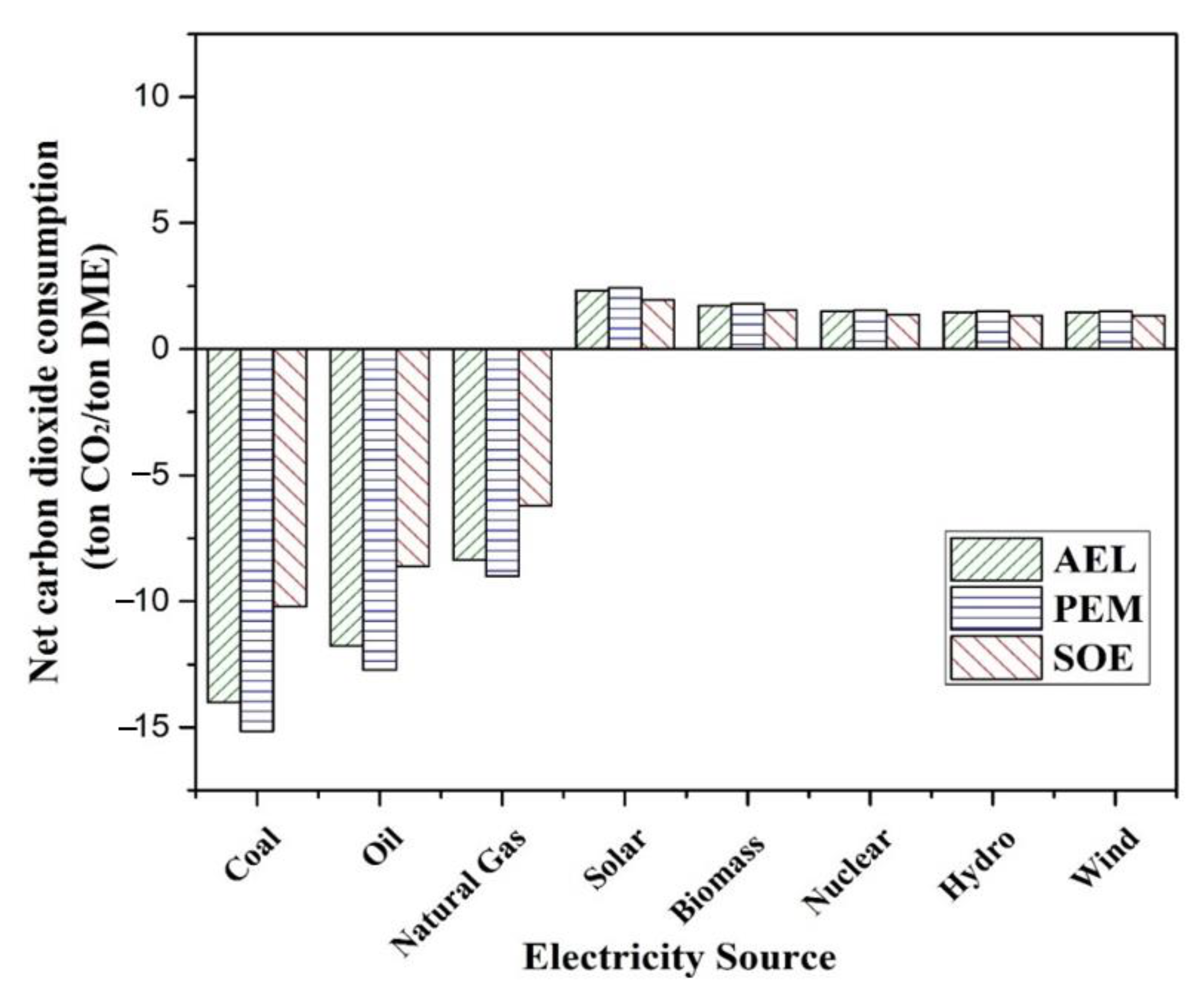
In Figure 12 the net CO2 consumption for AEL-Methanol-DME, PEM-Methanol-DME and SOE-Methanol-DME integrated processes is calculated using Equation (18). Here, the net consumptions are higher as compared to Figure 11. In DME integrated processes, the additional factor in the overall CO2 consumption calculation is the utility utilization in the DME production process. Biomass, hydro, nuclear and wind sources have almost same consumption of CO2 consumption while the highest consumption is for solar energy.
The SOE-Methanol-DME integrated process would have saved emissions of 2.9 tons of CO2/ton of DME if the SMR process was used and an additional 1.7 tons of CO2/ton of DME are utilized, which would result in saving a total of 4.7 tons of CO2/ton of DME; the cost of CO2 avoided is $68/ton of CO2. The AEL-Methanol-DME integrated process has a cost of CO2 avoided of $139/ton of CO2 since 2.6 tons of CO2/ton of DME were saved in addition to 2 tons of CO2/ton of DME resulting from solar energy; it thus saved a total of a4.6 tons of CO2/ton of DME. In the same way, PEM-Methanol-DME has a cost of CO2 mitigation of $78/ton of CO2 since it avoids producing a total 5.2 tons of CO2/ton of DME.
The total carbon balance for both methanol and DME integrated processes is shown in Table 7 with total CO2 consumption, CO2 avoided, and cost of CO2 mitigated, i.e., $/CO2 avoided or mitigated. The values are mentioned for RE, i.e., solar energy in this case, since it has the greater consumption of CO2 in both cases (Figure 11 and Figure 12).
For producing 1 ton of methanol, a cost of $145/ton of CO2 mitigated for AEL based methanol production is required. Any value of carbon tax equal to or greater than $145/ton of CO2 released to the environment will make the AEL based methanol production economically feasible. However, for producing 1 ton of methanol, a cost of $82/ton of CO2 mitigated for PEM based methanol production is required. Any value of carbon tax equal to or greater than $82/ton of CO2 released to the environment will make the PEM based methanol production process economically feasible. For instance, in Sweden (where the carbon tax is € 117.30) the PEM based methanol production process will be economically viable, but the AEL based methanol production process will not be economically viable.

5. Conclusions

The simulation results demonstrate that methanol production by hydrogenation of CO2 along with dehydration of methanol to DME has the potential to mitigate CO2 emissions. The technique also responds to the issues of GHGs emissions and global warming. The production of DME and methanol would not only reduce the consumption of fossil fuels but also provide feedstock for various chemicals. However, currently these processes are economically infeasible owing to the high cost associated with hydrogen production using water electrolysis techniques. The cost of hydrogen production by water electrolysis techniques must be reduced and still further improvements are required for commercial implementation of these processes. If the utility services for methanol and DME are supplied by RE sources instead of conventional processes, the net CO2 emissions would decrease. The cost per ton of methanol is $920/ton for AEL, $760/ton and $701/ton using PEM and SOE, respectively. The cost for methanol is highest using AEL and lowest using SOE. However, this cost is still significantly higher than the market price of methanol, i.e., 539 $/ton [38]. This study reports that in the methanol production process, the major cost burden is the hydrogen production. Hydrogen production by SOE required 416 MW of electrical energy, significantly lower than that required by AEL (590 MW) and PEM (652 MW). The cost per ton of DME using SOE-Methanol-DME production, PEM-Methanol-DME production and AEL-Methanol-DME production is $1141/ton, $1230/ton and $1471/ton, respectively. The SOE-Methanol-DME production process has the lowest cost for DME but is still 30% higher than the market price of DME, i.e., $888/ton.
It is clear from the above discussions that methanol and DME production can mitigate CO2 emissions. Methanol and DME production from CO2 can provide environmentally neutral fuels to power future vehicles. However, these processes can be implemented on a commercial scale if the costs of hydrogen production, notably water electrolysis, are further reduced. Since hydrogen production methods such as AEL, SOE and PEM have an electricity cost of 70 €/MWh [15], if the cost of electricity is reduced or electricity is provided at some discounted rate for the production of hydrogen using water electrolysis, these processes of hydrogen production would be economically feasible and can be implemented on a commercial scale. As for methanol and DME, some other processes for the chemical utilization of CO2, such as production of formaldehyde or acetic acid, can be considered in view of the global concerns of CO2 mitigation, reducing the consumption of fossil fuels and providing economical alternative fuels with no hazardous emissions.

Supplementary Materials

The following supporting information can be downloaded at: https://www.mdpi.com/article/10.3390/resources11100085/s1, Table S1: Results of mass and energy balance for hydrogen production process by alkaline water electrolysis (AEL) corresponding to Figure 3 of the manuscript. Table S2: Results of mass and energy balance for hydrogen production process by proton exchange membrane (PEM) corresponding to Figure 4 of the manuscript. Table S3: Results of mass balance for hydrogen production process solid oxide electrolyzer (SOE) corresponding to Figure 5 of the manuscript. Table S4: Results of energy balance for hydrogen production process solid oxide electrolyzer (SOE) corresponding to Figure 5 of the manuscript.Table S5: Results of mass balance for methanol production process corresponding to Figure 6 of the manuscript. Table S6: Results of energy balance for methanol production process corresponding to Figure 6 of the manuscript. Table S7: Results of mass and energy balance for DME production process corresponding to Figure 7 of the manuscript.

Author Contributions

Conceptualization, M.Z., Y.M., A.M. and A.E.; methodology, Y.M., M.Y., M.A., M.Z. and A.M.; software, M.Z. and Y.M.; validation, A.M., M.A., M.R. and M.Y.; formal analysis, Y.M., M.Y., M.A. and A.M.; investigation, Y.M., M.Y., A.M. and M.A.; resources, A.E. and M.Z.; data curation, A.M., Y.M., M.Y. and M.A.; writing—original draft preparation, Y.M., M.Y., M.R., M.Z. and A.E.; writing—review and editing, Y.M., M.Y., M.Z. and A.E; visualization, Y.M. and M.Y.; supervision, M.Z.; project administration, A.E. and M.Z.; funding acquisition, M.Z. and A.E. All authors have read and agreed to the published version of the manuscript.

Funding

This research was supported by National Research Program for Universities (NRPU, No: 6090/Federal/NRPU/R&D/HEC/2016) funded by the Higher Education Commission (HEC) of Pakistan. This research has also been financially supported in part by the Natural Sciences and Engineering Research Council of Canada (NSERC) and Khalifa University.

Conflicts of Interest

The authors declare no conflict of interest.

Nomenclature

Acronyms
ACCAnnual Capital CostkWKilo Watt
ACM®ASPEN Custom ModelerLHHWLangmuir-Hinshelwood-Hougen-Watson
AELAlkaline Water ElectrolysisMEAMono Ethanol Amine
AOCAnnual Operating CostM$Million US dollars
APEA®ASPEN Process Economic AnalyzerMWMega Watt
CCSCarbon Capture and SequestrationORCOrganic Rankine Cycle
CCUCarbon Capture and UtilizationPEMProton Exchange Membrane
CCUSCarbon Capture Utilization and SequestrationPtLPower to Liquid
COECost of ElectricityREsRenewable Energies
CRFCapital Recovery FactorRESRenewable Energy Sources
DMCDimethyl CarbonateRWGSReverse Water Gas Shift
DMEDimethyl EtherSMRSteam Methane Reforming
EGREnhanced Gas RecoverySOESolid Oxide Electrolyzer
EOREnhanced Oil RecoveryTACTotal Annual Cost
GHGGreen House GasesYSZYttria Stabilized Zirconia
Symbols
AAmperesMPaMega Pascal
AtotalArea of electrolysisɳcCarnot Efficiency
CColumbzNo. of electrons transferred
°CDegrees CelsiusɳenEnergy Efficiency
CcapitalCapital costɳexeExergy Efficiency
EinEnergy Input   n   ˙ o Molar flow rate of water ion (mol/s)
FFaraday’s ConstantQinHeat input
∆GGibbs free energy change∆SEntropy change
hEnthalpyTcTemperature of heat sink
hrHourUrevReversible voltage
∆HEnthalpy changeutyUtility
jInterest rateWnetNet work
iCurrent densityWpPump work
ItotalTotal currentWtTurbine work
kJKilo JoulesThTemperature of heat source
mMass flow rateEuro
molMoles$US Dollar

Appendix A

Figure A1. Hydrogen Produced by AEL to Methanol Plant.
Resources 11 00085 g0a1
Figure A2. Hydrogen Produced by PEM to Methanol Plan.
Resources 11 00085 g0a2

References

  1. Zaman, M.; Lee, J.H. Carbon capture from stationary power generation sources: A review of the current status of the technologies. Korean J. Chem. Eng. 2013, 30, 1497–1526. [Google Scholar] [CrossRef]
  2. NOAA Research News, Carbon Dioxide Peaks Near 420 Parts per Million at Mauna Loa Observatory, June 2021. Available online: https://research.noaa.gov/article/ArtMID/587/ArticleID/2764/Coronavirus-response-barely-slows-rising-carbon-dioxide (accessed on 22 July 2022).
  3. Rubin, E.S.; Chen, C.; Rao, A.B. Cost and performance of fossil fuel power plants with CO2 capture and storage. Energy Policy 2007, 35, 4444–4454. [Google Scholar] [CrossRef]
  4. Buckingham, J.; Reina, T.R.; Duyar, M.S. Recent advances in carbon dioxide capture for process intensification. Carbon Capture Sci. Technol. 2022, 2, 100031. [Google Scholar] [CrossRef]
  5. Zaman, M.; Jang, H.; Rizwan, M.; Lee, J.H. Optimal design for flexible operation of the post-combustion CO2 capture plant with uncertain economic factors. Comput. Chem. Eng. 2016, 84, 199–207. [Google Scholar] [CrossRef]
  6. Sheikh, H.M.; Ullah, A.; Hong, K.; Zaman, M. Thermo-economic analysis of integrated gasification combined cycle (IGCC) power plant with carbon capture. Chem. Eng. Process.-Process Intensif. 2018, 128, 53–62. [Google Scholar] [CrossRef]
  7. Adnan, M.; Zaman, M.; Ullah, A.; Güngör, A.; Rizwan, M.; Naqvi, S.R. Thermo-Economic Analysis of Integrated Gasification Combined Cycle Co-Generation System Hybridized with Concentrated Solar Power Tower. Renew. Energy 2022, 198, 654–666. [Google Scholar] [CrossRef]
  8. Adnan, M.; Zaman, M.; Ullah, A.; Güngör, A. Thermo-economic evaluation of integrated gasification combined cycle co-generation system with carbon capture: A Pakistan’s perspective. In Proceedings of the 2021 4th International Conference on Energy Conservation and Efficiency (ICECE), Lahore, Pakistan, 16–17 March 2021. [Google Scholar]
  9. Hakeem, L.; Khan, M.A.; Muhammad, R.; Elkamel, A.; Muhammad, Z. A multi-period optimization model for power sector with CO2 emission considerations. Int. J. Energy Res. 2022, 46, 2655–2673. [Google Scholar] [CrossRef]
  10. Muhammad, A.; Muhammad, Z.; Ullah, A.; Muhammad, R.; Ramzan, N. Thermo-economic analysis of integrated gasification combined cycle co-generation system with carbon capture and integrated with absorption refrigeration system. Energy Convers. Manag. 2021, 248, 114782. [Google Scholar] [CrossRef]
  11. Cuéllar-Franca, R.M.; Azapagic, A. Carbon capture, storage and utilisation technologies: A critical analysis and comparison of their life cycle environmental impacts. J. CO2 Util. 2015, 9, 82–102. [Google Scholar] [CrossRef]
  12. Aresta, M.; Dibenedetto, A. Utilisation of CO2 as a chemical feedstock: Opportunities and challenges. J. Chem. Soc. Dalt. Trans. 2007, 2975–2992. [Google Scholar] [CrossRef]
  13. Khalafalla, S.S.; Zahid, U.; Abdul Jameel, A.G.; Ahmed, U.; Alenazey, F.S.; Lee, C.J. Conceptual design development of coal-to-methanol process with carbon capture and utilization. Energies 2020, 13, 6421. [Google Scholar] [CrossRef]
  14. Phongamwong, T.; Chantaprasertporn, U.; Witoon, T.; Numpilai, T.; Poo-arporn, Y.; Limphirat, W.; Donphai, W.; Dittanet, P.; Chareonpanich, M.; Limtrakul, J. CO2 hydrogenation to methanol over CuO–ZnO–ZrO2–SiO2 catalysts: Effects of SiO2 contents. Chem. Eng. J. 2017, 316, 692–703. [Google Scholar] [CrossRef]
  15. Ma, J.; Sun, N.; Zhang, X.; Zhao, N.; Xiao, F.; Wei, W.; Sun, Y. A short review of catalysis for CO2 conversion. Catal. Today 2009, 148, 221–231. [Google Scholar] [CrossRef]
  16. Bowker, M. Methanol Synthesis from CO2 Hydrogenation. ChemCatChem 2019, 11, 4238. [Google Scholar] [CrossRef]
  17. Van-Dal, É.S.; Bouallou, C. CO2 abatement through a methanol production process. Chem. Eng. Trans. 2012, 29, 463–468. [Google Scholar] [CrossRef]
  18. Lonis, F.; Tola, V.; Cau, G. Assessment of integrated energy systems for the production and use of renewable methanol by water electrolysis and CO2 hydrogenation. Fuel 2021, 285, 119160. [Google Scholar] [CrossRef]
  19. Yousaf, M.; Mahmood, A.; Elkamel, A.; Rizwan, M.; Zaman, M. Techno-economic analysis of integrated hydrogen and methanol production process by CO2 hydrogenation. Int. J. Greenh. Gas Control 2022, 115, 103615. [Google Scholar] [CrossRef]
  20. Sumalatha, B.; Narayana, A.V.; Kiran Kumar, K.; Babu, D.J.; Venkateswarulu, T.C. Design and simulation of a plant producing dimethyl ether (DME) from methanol by using simulation software ASPEN PLUS. J. Chem. Pharm. Res. 2015, 7, 897–901. [Google Scholar]
  21. Alshbuki, E.H.; Bey, M.M.; Mohamed, A. Ala. Simulation Production of Dimethylether (DME) from Dehydration of Methanol Using Aspen Hysys. Sch. Int. J. Chem. Mater. Sci. 2020, 3, 13–18. [Google Scholar] [CrossRef]
  22. Babiker, H.; Karma, B.; Mohammed, A.A. AspenHysys Simulation of Methanol to Dimethylether DME. Int. J. Eng. Trends Technol. 2017, 46, 214–220. [Google Scholar] [CrossRef]
  23. Matzen, M.; Demirel, Y. Methanol and dimethyl ether from renewable hydrogen and carbon dioxide: Alternative fuels production and life-cycle assessment. J. Clean. Prod. 2016, 139, 1068–1077. [Google Scholar] [CrossRef] [Green Version]
  24. Nikolaidis, P.; Poullikkas, A. A comparative overview of hydrogen production processes. Renew. Sustain. Energy Rev. 2017, 67, 597–611. [Google Scholar] [CrossRef]
  25. Koj, J.C.; Wulf, C.; Schreiber, A.; Zapp, P. Site-dependent environmental impacts of industrial hydrogen production by alkalinewater electrolysis. Energies 2017, 10, 860. [Google Scholar] [CrossRef]
  26. Zeng, K.; Zhang, D. Recent progress in alkaline water electrolysis for hydrogen production and applications. Prog. Energy Combust. Sci. 2010, 36, 307–326. [Google Scholar] [CrossRef]
  27. Brauns, J.; Turek, T. Alkaline water electrolysis powered by renewable energy: A review. Processes 2020, 8, 248. [Google Scholar] [CrossRef]
  28. Yao, J.; Kraussler, M.; Benedikt, F.; Hofbauer, H. Techno-economic assessment of hydrogen production based on dual fluidized bed biomass steam gasification, biogas steam reforming, and alkaline water electrolysis processes. Energy Convers. Manag. 2017, 145, 278–292. [Google Scholar] [CrossRef]
  29. Schmidt, O.; Gambhir, A.; Staffell, I.; Hawkes, A.; Nelson, J.; Few, S. Future cost and performance of water electrolysis: An expert elicitation study. Int. J. Hydrogen Energy 2017, 42, 30470–30492. [Google Scholar] [CrossRef]
  30. Sánchez, M.; Amores, E.; Abad, D.; Rodríguez, L.; Clemente-Jul, C. Aspen Plus model of an alkaline electrolysis system for hydrogen production. Int. J. Hydrogen Energy 2020, 45, 3916–3929. [Google Scholar] [CrossRef]
  31. Ogungbemi, E.; Ijaodola, O.; Khatib, F.N.; Wilberforce, T.; El Hassan, Z.; Thompson, J.; Ramadan, M.; Olabi, A.G. Fuel cell membranes—Pros and cons. Energy 2019, 172, 155–172. [Google Scholar] [CrossRef]
  32. Zaccara, A.; Petrucciani, A.; Matino, I.; Branca, T.A.; Dettori, S.; Iannino, V.; Colla, V.; Bampaou, M.; Panopoulos, K. Renewable hydrogen production processes for the off-gas valorization in integrated steelworks through hydrogen intensified methane and methanol syntheses. Metals 2020, 10, 1535. [Google Scholar] [CrossRef]
  33. Mancera, J.J.C.; Manzano, F.S.; Andújar, J.M.; Vivas, F.J.; Calderón, A.J. An optimized balance of plant for a medium-size PEM electrolyzer. Design, control and physical implementation. Electron. 2020, 9, 871. [Google Scholar] [CrossRef]
  34. Gagliardi, G.G.; Ibrahim, A.; Borello, D.; El-Kharouf, A. Composite polymers development and application for polymer electrolyte membrane technologies-a review. Molecules 2020, 25, 1712. [Google Scholar] [CrossRef] [PubMed]
  35. Van-Dal, É.S.; Bouallou, C. Design and simulation of a methanol production plant from CO2 hydrogenation. J. Clean. Prod. 2013, 57, 38–45. [Google Scholar] [CrossRef]
  36. Quarterly Report: On European Electricity Markets, Volume 10; European Commission: Brussels, Belgium, 2017.
  37. Villain-Gambier, M.; Courbalay, M.; Klem, A.; Dumarcay, S.; Trebouet, D. Recovery of lignin and lignans enriched fractions from thermomechanical pulp mill process water through membrane separation technology: Pilot-plant study and techno-economic assessment. J. Clean. Prod. 2020, 249, 119345. [Google Scholar] [CrossRef]
  38. Meunier, N.; Chauvy, R.; Mouhoubi, S.; Thomas, D.; De Weireld, G. Alternative production of methanol from industrial CO2. Renew. Energy 2020, 146, 1192–1203. [Google Scholar] [CrossRef]
  39. Luyben, W.L. Design and control of a methanol reactor/column process. Ind. Eng. Chem. Res. 2010, 49, 6150–6163. [Google Scholar] [CrossRef]
  40. Pérez-Fortes, M.; Tzimas, E. Techno-economic and environmental evaluation of CO2 utilisation for fuel production. Synthesis of methanol and formic acid. Sci. Tech. Res. Ser. 2016, 85. [Google Scholar] [CrossRef]
  41. World Nuclear Association. Comparison of Lifecycle Greenhouse Gas Emissions of Various Electricity Generation Sources; World Nuclear Association: London, UK, 2011; p. 10. [Google Scholar]
  42. Kuckshinrichs, W.; Ketelaer, T.; Koj, J.C. Economic analysis of improved alkaline water electrolysis. Front. Energy Res. 2017, 5, 1. [Google Scholar] [CrossRef]
  43. Paquin, F.; Rivnay, J.; Salleo, A.; Stingelin, N.; Silva, C. Multi-phase semicrystalline microstructures drive exciton dissociation in neat plastic semiconductors. J. Mater. Chem. C 2015, 3, 10715–10722. [Google Scholar] [CrossRef] [Green Version]
Figure 1. Hydrogen production methods.
Resources 11 00085 g001
Figure 2. Schematic of proposed integrated process.
Resources 11 00085 g002
Figure 3. Alkaline water electrolysis flowsheet in ASPEN Plus®.
Resources 11 00085 g003
Figure 4. Proton exchange membrane flowsheet in ASPEN Plus®.
Resources 11 00085 g004
Figure 5. Hydrogen produced by SOE.
Resources 11 00085 g005
Figure 6. Methanol production using hydrogenation of carbon dioxide.
Resources 11 00085 g006
Figure 7. Dimethyl ether production from dehydration of methanol.
Resources 11 00085 g007
Figure 8. Comparison of SOE [19], AEL and PEM with same amount of hydrogen produced.
Resources 11 00085 g008
Figure 9. Economic comparison of SOE, AEL and PEM Integrated Methanol Production.
Resources 11 00085 g009
Figure 10. Comparison of cost per ton of DME.
Resources 11 00085 g010
Figure 11. Net carbon balance for methanol production.
Resources 11 00085 g011
Figure 12. Net carbon balance for DME production.
Resources 11 00085 g012
Table 1. Brief description of three cases.
Case No.Description
Case—I Hydrogen Production Processes
i.
AEL: The electrolyte KOH was used for water electrolysis with T = 75 °C and P = 25 bar.
ii.
PEM: Nafion® membrane was used for water electrolysis with T = 80 °C and P = 25 bar.
iii.
SOE *: The solid oxide electrolyzer was used for water electrolysis with operating T = 800 °C.
Case—II Methanol Production Processes
i.
AEL–Methanol Production: Hydrogen produced by AEL was fed to Methanol Production plant at T = 184 °C and P = 78 bar.
ii.
PEM–Methanol Production: Hydrogen produced by PEM was fed to Methanol Production plant at T = 129 °C and P = 78 bar.
iii.
SOE–Methanol Production *: Hydrogen produced by SOE was fed to Methanol Production plant at T = 192 °C and P = 78 bar.
CO2 was obtained from a cement plant in all above mentioned methanol production processes.
Case—III DME Production Processes
i.
AEL-Methanol-DME Production: AEL produced H2, after CO2 hydrogenation produces methanol and sent to DME production at T = 40 °C and P = 1 bar.
ii.
PEM-Methanol-DME Production: PEM produced H2, after CO2 hydrogenation produces methanol and sent to DME production at T = 40 °C and P = 1 bar.
iii.
SOE-Methanol-DME Production: SOE produced H2, after CO2 hydrogenation produces methanol and sent to DME production at T = 40 °C and P = 1 bar.
* Results are taken from Yousaf et al. [19].
Table 2. Economic parameters used in hydrogen and methanol production processes.
ParameterIn the LiteratureUpdated Value
Cost of electricity (COE)0.07 € 2020/kWh [36]$0.083 2022/kWh *
Demineralized water0.12 € 2020/m3 [37]$0.144 2022/m3 *
Captured CO224.38 € 2020/ton [38]$23.23 2022/ton *
H2 feed cost (AEL)3956 € 2020/ton [38]$4743 2022/ton *
Catalyst cost$10 2010/kg [39]$12.9 2022/kg **
Interest rate (j)8%8%
Plant life AEL20 years20 years
SOE Cell life [19]5 years5 years
PEM Membrane life11 years11 years
Oxygen market price54 € 2016/ton [40]$69.5 2022/ton *,**
Methanol market price450 € 2020/ton [38]$539 2022/ton *
DME market price$493 2007/ton$686 2022/ton
* € to $ conversion factor is taken to be 1.10 (the average of May 2022); ** Currency of previous years is converted to equivalent values in 2022 based on the inflation rates.
Table 3. Validation of AEL and PEM processes.
ParametersThis WorkFrancesco et al. [18]Absolute Deviation (%)
Validation of AEL
Hydrogen Production(kg/s)75.5760.6
Power(kW)350034501.4
Electronic Efficiency (%)71732.7
mH2LHVH2(kW)251225200.3
Feed H2O (kg/s)97.897.8-
ParametersThis WorkZaccarra et al. [32]Absolute Deviation (%)
Validation of PEM
H2O Feed (kg/kg H2)9.59.83
Power (MW)206819883.8
Electricity Required (kWh/kg H2)53541.8
Table 4. Comparison of SOE, AEL and PEM based on same amount of hydrogen produced.
ParametersSOE [19]PEMAEL
Amount of H2 produced (kg/hr)12,12212,12212,122
Water inlet (kg/hr)110,326109,435108,443
Amount of O2 produced (kg/hr)96,21397,17996,212
Capital Cost from APEA (M$)6123
Utilities Cost (M$/yr)28.020.040.38
Raw Materials Cost (M$/yr)0.120.14108.00
Operating Cost from APEA (M$/yr)34.871.10119.00
Amount of H2 produced (ton/yr)117,560117,133117,138
CRF0.1175Plant: 0.1018, Membrane: 0.130.1019
Power (MW)416642590
Cost of Electricity (M$/yr)301464427
Stack Area (m2)28,78081,256107,446
Per ton H2 cost ($/ton)363539904663
ACC (M$/yr)7.131.720.35
AOC (M$/yr)390466545
TAC (M$/yr)398467546
Table 5. Comparison of Integrated Methanol Processes.
ParametersUnitsSOEPEMAEL
MethanolMethanol Producedkg/hr63,54863,55063,550
Capital Cost of MethanolM$474747
Operating Cost of MethanolM$/yr373737
Utilities of MethanolM$/yr101010
ElectrolysisHydrogen Producedkg/hr12,16612,16612,166
Electricity RequiredkW416,104646,831596,822
Utilities other than electrolysisM$/yr330.047.92
Capital CostM$2662.28.1
Operating CostM$/yr401.1127
Electricity CostM$/yr275427394
Total UtilitiesM$/yr308427402
Aream228,78081,314161,169
TotalTotal CapitalM$3165359
AOCM$/yr352465558
ACCM$/yr4.41.86.9
TACM$/yr405466.8565.1
Cost per ton methanol$/ton701760920
O2 Produced per ton methanolkg O2/kg Methanol1.51.51.5
Cost of Oxygen$/ton methanol969696
Cost per ton Methanol after
Selling O2
$/ton methanol605662823
Table 6. Comparison of DME production processes.
ParametersConventional Methods for DME Production [38]SOE-Methanol-DME Integrated Process [19]PEM-Methanol-DME Integrated ProcessAEL-Methanol-DME Integrated Process
Cost of Methanol ($/ton) *539701760920
Amount of DME (tons/yr)431,469431,469431,469431,469
Capital Cost (M$/yr)1111
Utilities Cost (M$/yr)32323232
Raw Material Cost (M$/yr)319420456552
AOC (M$/yr)382491529633
TAC (M$/yr)383492531635
Cost per ton of DME ($/ton)888114112301471
Cost per ton DME after selling O2 ($/ton)---100410931332
* Taken from previous section, Table 5.
Table 7. Carbon Balance for Methanol and DME Integrated Processes.
ParametersSOEPEMAEL
MethanolDMEMethanolDMEMethanolDME
CO2 consumed (tons per ton of methanol/DME produced)0.51.70.862.50.792
CO2 avoided (tons per ton of methanol/DME produced)2.94.72.75.22.64.6
Cost of CO2 mitigation/ avoided ($/ton of CO2)55688278145139
Publisher’s Note: MDPI stays neutral with regard to jurisdictional claims in published maps and institutional affiliations.