Article

Ensuring the Sustainability of Arctic Industrial Facilities under Conditions of Global Climate Change

Arctic Competence Center, Saint Petersburg Mining University, 199106 Saint Petersburg, Russia
*
Author to whom correspondence should be addressed.
Resources 2021, 10(12), 128; https://doi.org/10.3390/resources10120128
Submission received: 30 October 2021 / Revised: 23 November 2021 / Accepted: 13 December 2021 / Published: 15 December 2021
(This article belongs to the Special Issue Resource Provision of the Sustainable Development under Global Shocks)

Abstract

:
Global climate change poses a challenge to the mineral development industry in the Arctic regions. Civil and industrial buildings designed and constructed without consideration of warming factors are beginning to collapse due to changes in the permafrost structure. St. Petersburg Mining University is developing technical and technological solutions for the construction of remote Arctic facilities and a methodology for their design based on physical and mathematical predictive modeling. The article presents the results of modeling the thermal regimes of permafrost soils in conditions of thermal influence of piles and proposes measures that allow a timely response to the loss of bearing capacity of piles. Designing pile foundations following the methodology proposed in the article to reduce the risks from global climate change will ensure the stability of remote Arctic facilities located in the zone of permafrost spreading.

1. Introduction

Combating climate change is the United Nations’ 13th Sustainable Development Goal [1]. According to the UN Intergovernmental Panel on Climate Change (IPCC) [2], the Arctic is warming faster than the rest of the world, which is highlighted in every report. For example, a global warming has already reached 1 °C above pre-industrial period (1850–1900). At the same time, the measured temperature increase in the Arctic was two to three times higher, and there were significant differences between Arctic regions [3]. IPCC climate models predict that this trend will continue: a 2 °C increase by 2100 globally is projected to result in a 4–7 °C increase in Arctic temperatures.
There are a number of studies on climate change on Earth that link warming processes with anthropogenic greenhouse gas emissions [4,5]. Global anthropogenic greenhouse gas emissions increased by 1.7% in 2017 and by about 2.7% in 2018 [6]. But even with all current national commitments to reduce greenhouse gas emissions, an average global average annual temperature increases of 3 °C is projected, corresponding to an average nighttime temperature increase of 7–11 °C in the Arctic [3].
Over the past decades, global warming has led to a widespread decrease in the cryosphere with loss of ice sheet and glacier mass, reduction in snow cover, and an increase in the area and thickness of Arctic sea ice, as well as an increase in permafrost temperatures [7]. Permafrost temperatures have risen to record-high levels (from 1980 to the present), including a recent increase of 0.29 ± 0.12 °C from 2007 to 2016 in the average polar and high-altitude regions of the world. Widespread thawing of permafrost is expected with high confidence this century and in future years [2].
The relevance of developing solutions aimed at ensuring the stability of foundations of objects located in the zone of permafrost spreading has recently increased in light of global climate change on planet Earth. For example, the accident at CHPP-3 of Norilsk-Taimyr Energy Company on 29 May 2020, can be attributed to the consequences of the loss of bearing capacity of the foundations located in the permafrost spreading zone [8]. The incident spilled about 21,000 tons of oil products, of which 6000 tons ended up in the ground, and the rest in the Ambarnaya River and its tributary Daldykan, which flows into the large Pyasino Lake. From this lake flows the Pyasina River, which flows into the Kara Sea.

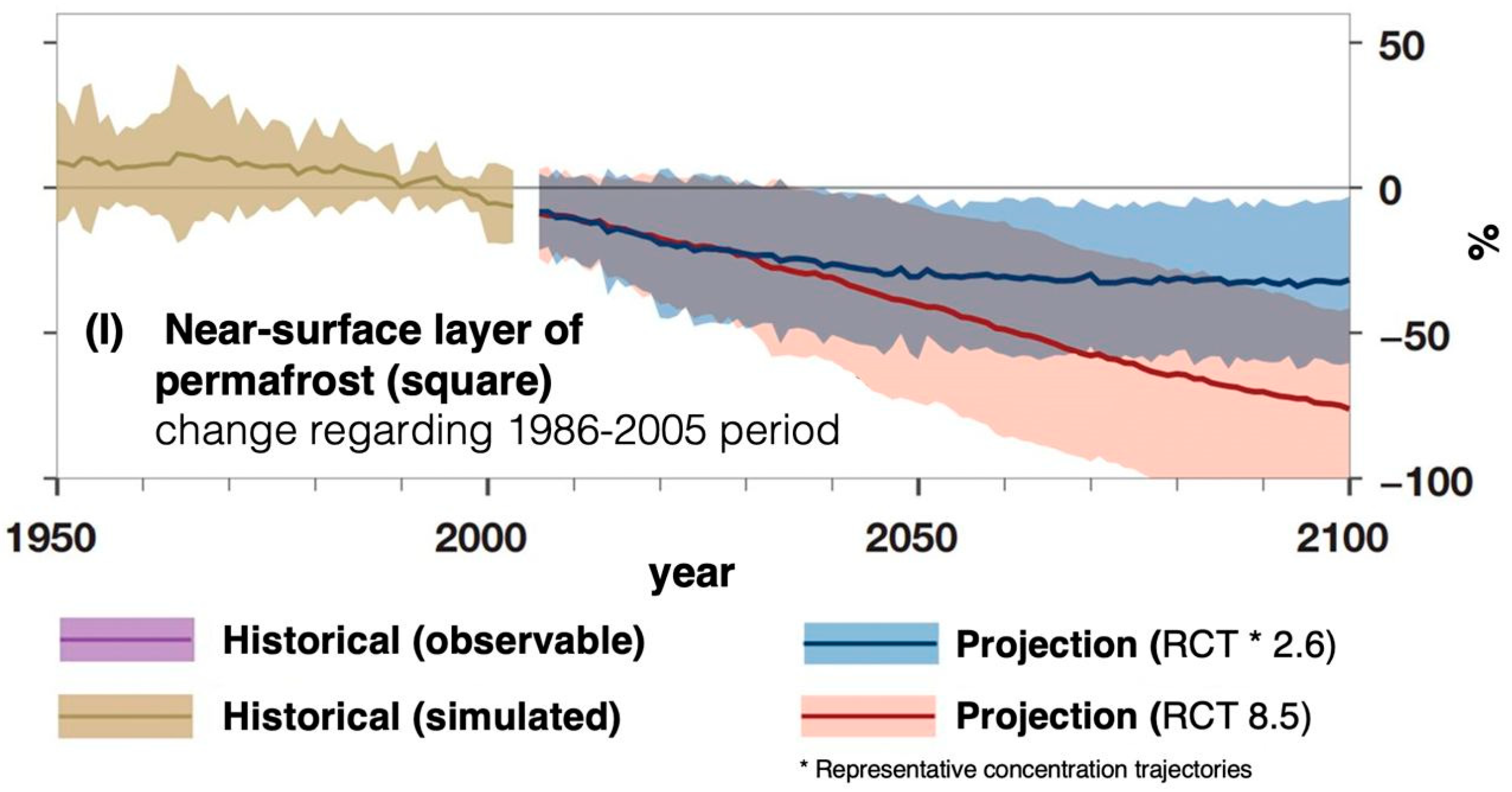
1.1. Increase of CO2 Emissions as Permafrost Melts

A number of studies have noted the acceleration of climate change processes in the Arctic region, while an inverse relationship is observed in the Antarctic [9,10]. It is predicted that melting permafrost in the Arctic will lead to the emission of “additional” 25–85 billion tons of greenhouse gases per year (in terms of carbon), given that all mankind emits about 13 billion tons of carbon [11]. As a result, tundra soils will not absorb, but release “extra” carbon dioxide and methane. Currently, the tundra and other areas of permafrost are among the absorbers of greenhouse gases—areas in which natural systems absorb more greenhouse gases, including CO2 and methane, than they are formed in this area. A large proportion is deposited in peat or soil, some of which is in a state of permafrost.
Due to higher temperatures and CO2 concentrations, plants will be able to absorb more carbon dioxide—their “productivity” will increase from 69 to 88 billion tons of carbon. On the other hand, the melting of permafrost will cause organic deposits in the tundra soil to “unfreeze” and begin to rot, releasing carbon dioxide and methane [12].
By 2100, according to projections, the near-surface (within 3–4 m) permafrost area will decrease by 24 ± 16% (probable range) for RTC2. 6 (scenario with warming of 1.1–2.0 °C during 2031–2050 and 0.9–2.4 °C during 2081–2100) and 69 ± 20% (probable range) for RTC8.5 (1.5–2.4 °C during 2031–2050 and 3.2–5.4 °C during 2081–2100), Figure 1 [2,6,7,13,14].

1.2. Rising Global Sea Levels and Risk to Infrustructure

For coastal regions, including the Arctic, sea level rise poses a threat to the stability of industrial structures [15,16]. The risk of seasonal flooding of such territories increases, including that caused by the formation of a surge wave in the water area [17,18,19].
Even if the world goes down the path of low greenhouse gas emissions, the global sea level is likely to rise at least 0.3 m above 2000 levels by 2100. If we go down the high emission pathway, we cannot rule out a worst-case scenario where the 2100 level will exceed the one of 2000 by 2.5 m [14,20].
About 60% of the territory of the Russian Federation is in the permafrost zone with major mineral reserves in it, as shown in Figure 2 [21,22,23,24,25,26]. One of the important tasks of ensuring sustainable functioning of facilities in the Arctic zone of the Russian Federation is to prevent defrosting and thawing of permafrost [27,28].
The wide distribution of permafrost over the entire Arctic shelf and the presence of an extremely harsh climate pose enormous difficulties for construction [29,30,31]. There are many ways of building objects in the Arctic conditions. For example, ventilated basement, which provides heat removal from the building and prevents its penetration into the ground, an injection consolidation technology or improvement of soil properties using Jet Grouting [32].
The main part of the shelf area under consideration is shallow, with prevailing depths of 1–3 m. Only in the extreme southern part of the area, the sea depth reaches 5 m and more. The presence of a weak subsoil base carries a risk associated with the insufficient stability of structures. For such conditions, the possibility of forced freezing with subsequent thermal stabilization of weak bottom sediments becomes topical in order to locate remote Arctic objects, both on land and at sea. Anyway, since the environmental impact of infrastructure facilities is known, it is necessary to apply the best technologies for the construction and operation of such facilities [33,34].
The aim of this paper is to search for answers to modern challenges arising from global climate change: thawing of permafrost and loss of stability of pile foundations, sea level rise and, as a consequence, an increase in the intensity of seasonal flooding of coastal Arctic territories.
The paper solves the problems related to design of modular pile foundations, modeling the consequences of global warming and its impact on the pile foundations bearing capacity, development a methodology for predicting changes [35] and monitoring changes during the operation of remote Arctic objects, development of measures for saving the bearing capacity of modular pile foundations.

2. Materials and Methods

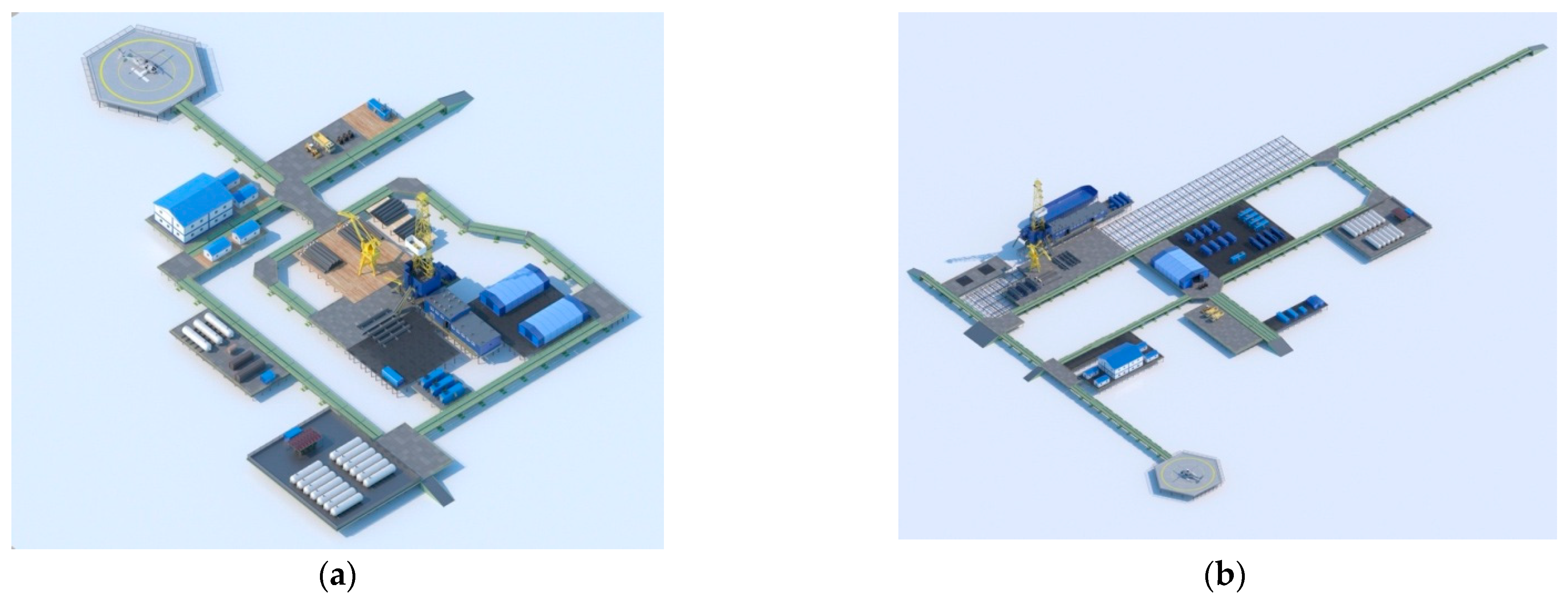
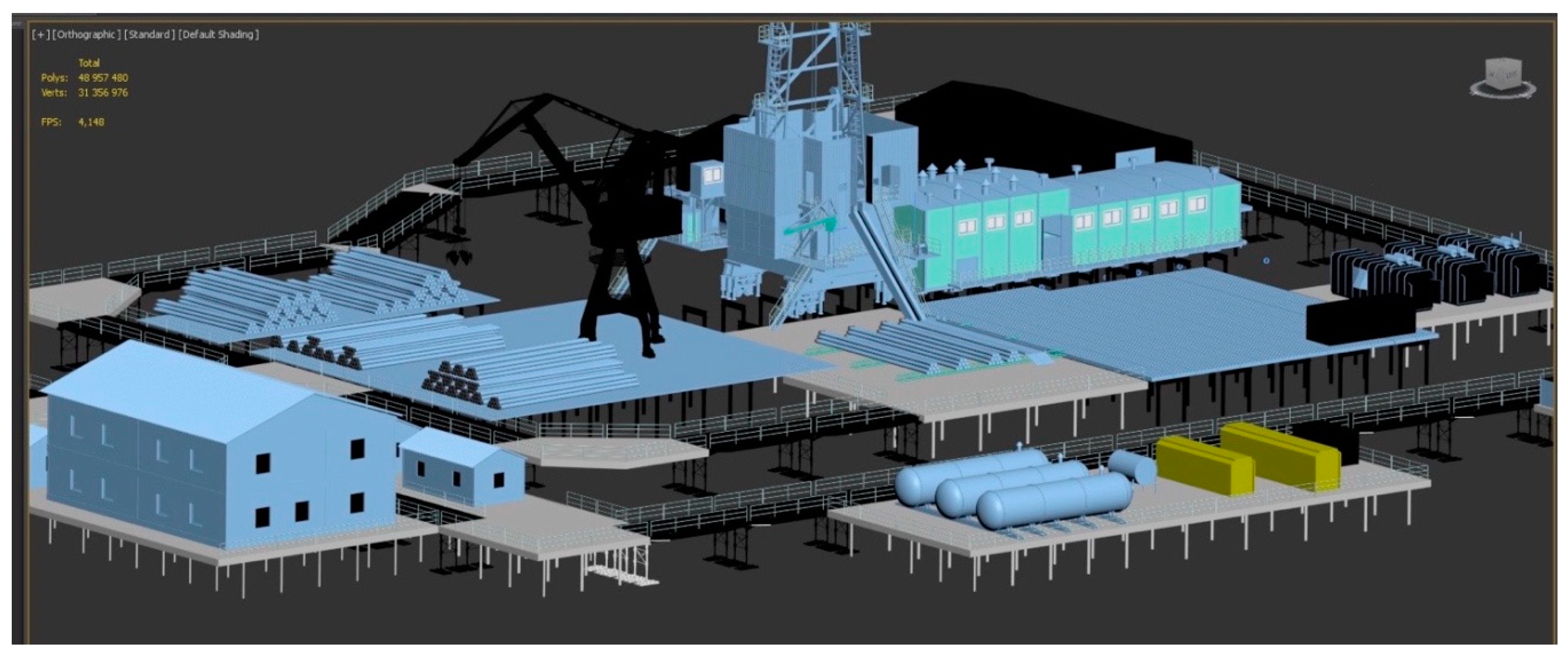
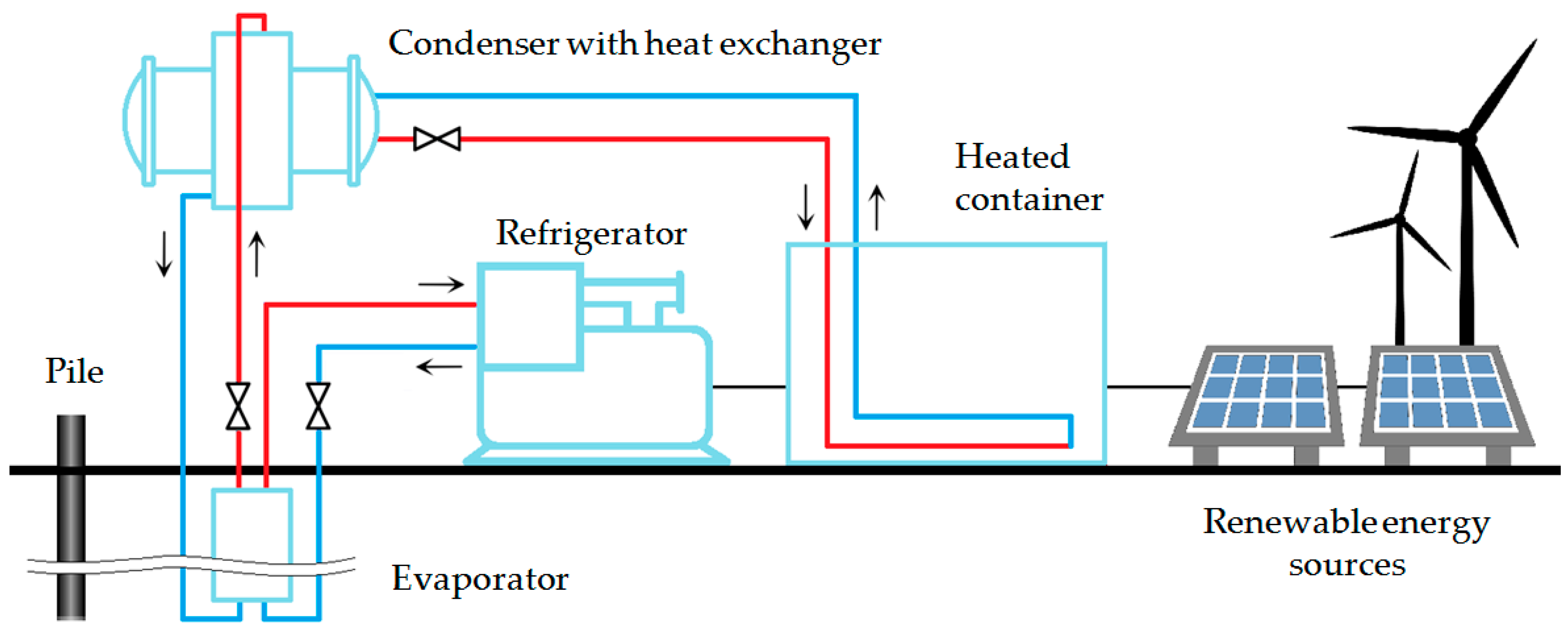
2.1. Proposed Solution for Remote Arctic Oil and Gas Facilities

The proposed solution for the creation of industrial infrastructure facilities is a pile foundation, mounted in wintertime with pre-strengthening of soils, see Figure 3.
The concept of creating modular pile foundations developed at Mining University [36,37] implies optimal placement and year-round operation of equipment production infrastructure facilities in the allocated technological zones. To implement these solutions, new types of piles or traditional foundations, which are widely used in construction work in areas of permafrost soils, can be used.
The Arctic Research Center of Mining University developed design documentation for modular pile foundations (Figure 4) for placing drilling rigs in zones of permafrost spreading, subject to seasonal flooding. As a result of the research and development, it was found that the cost of constructing modular pile foundations is on average 50% less than the cost of constructing and maintaining sand dumps [38].

2.2. Physical and Mathematical Modeling of Geotechnical Solutions for the Location of Arctic Oil and Gas Facilities under Climate Change

To select the best technological solutions, it is first necessary to understand how climate change in the Arctic zone affects the bearing capacity of the piles. For this purpose, according to statistical data, three warming scenarios for the period from 2031 to 2050 were developed as initial characteristics for modeling: (1) positive with a temperature increase of 2.2 °C (0.1 °C per year); (2) neutral with a temperature increase of 3 °C (0.16 °C per year); (3) negative with a temperature increase of 4.8 °C (0.24 °C per year); (4) locally negative with a temperature increase of 9.6 °C (0.5 °C per year). The initial data for modeling were obtained as a result of engineering surveys at a remote field in the Russian Arctic zone. The characteristics of soils for modeling the bearing capacity of foundations are summarized in Table 1.
The physical and mechanical properties of soils are determined from laboratory data. Additional parameters such as heat capacity and thermal conductivity of the material in the thawed and frozen state were calculated according to the Russian standardization document [39]. The average active layer, according to the surveys, was 0.5 m.
The initial meteorological data are average monthly and annual air temperature and wind speed. The data are shown in Table 2.
Modeling the distribution of soil temperatures around the pile and calculating the bearing capacity of the pile foundations was carried out in the Frost 3D software. In this researce we considered the air temperature increase to model active layer depth. However, there are other factors such as content of water [40,41,42], air content [42], organic matter [43], etc. Taking these factors into account is a direction for further research.

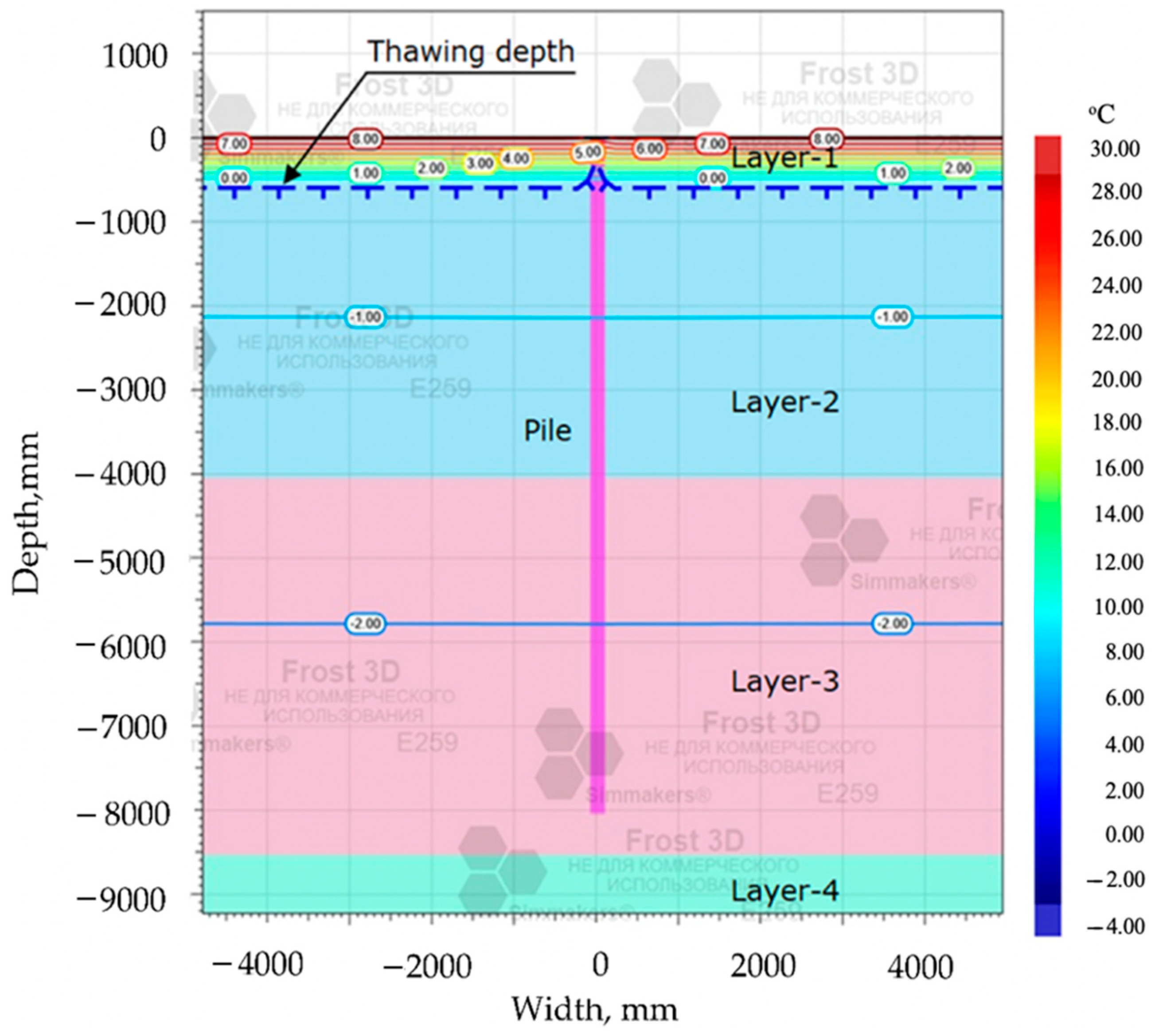
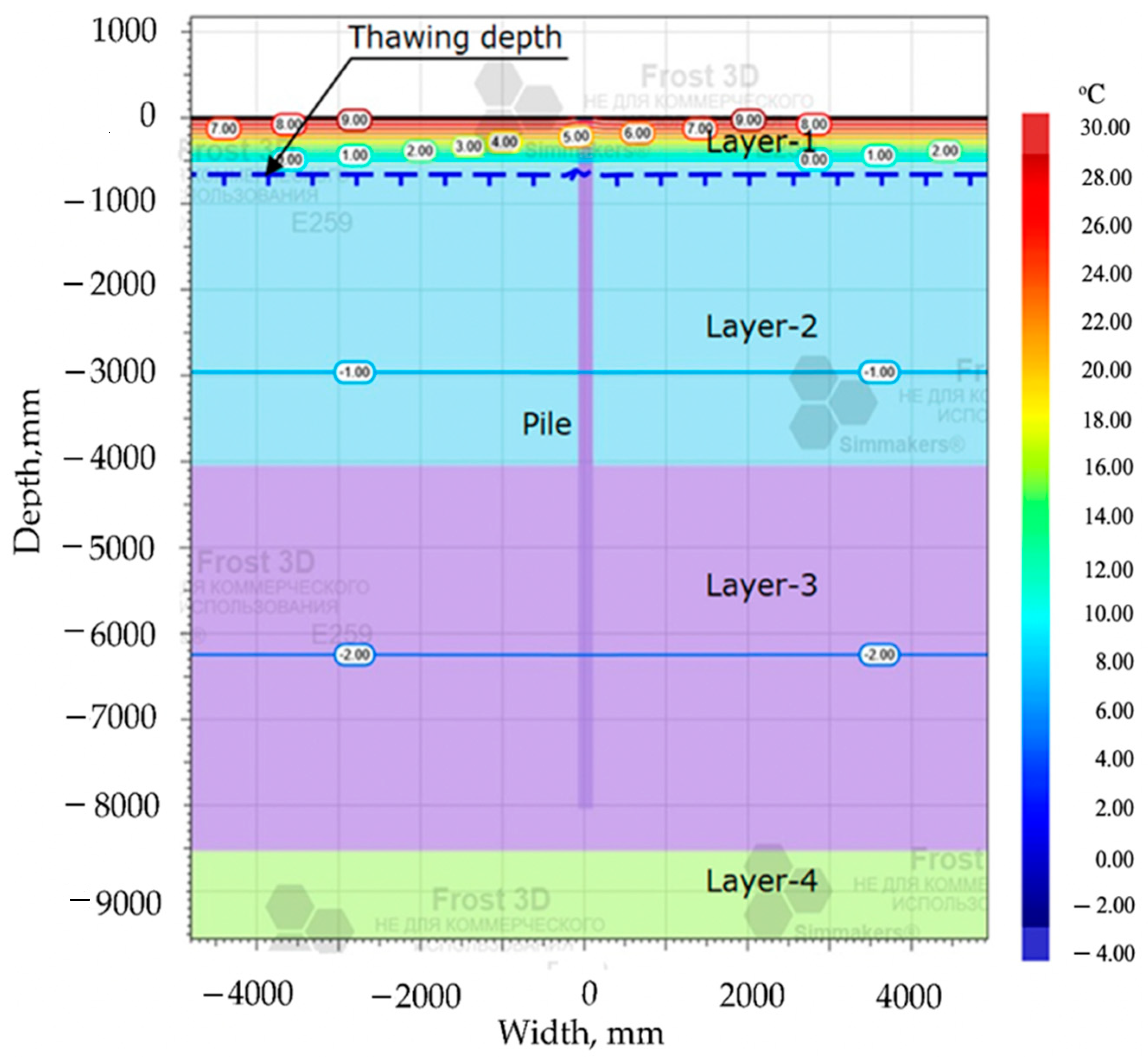
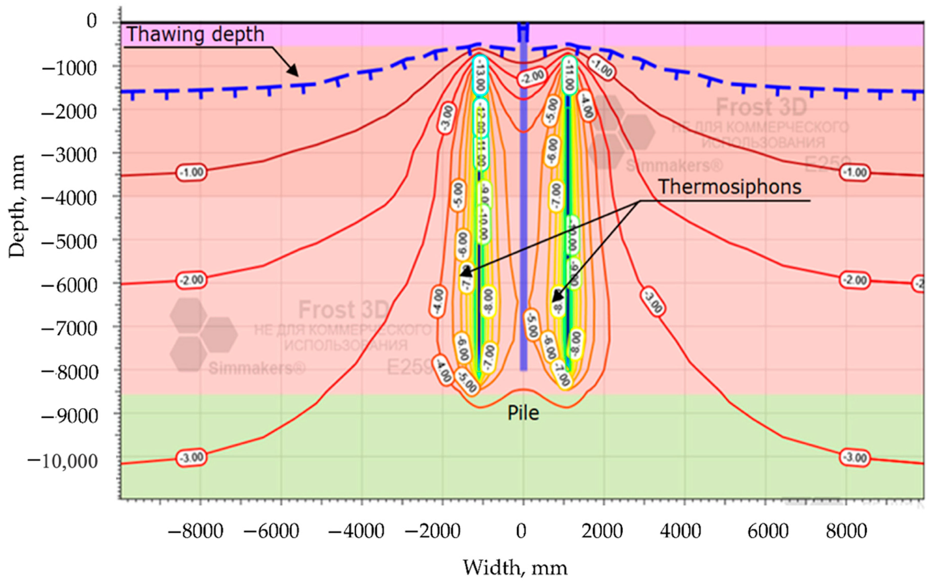
2.3. Proposed Solution for the Stability of Pile Foundations in Permafrost

Thermosyphons are an effective means of temperature stabilization of permafrost soils, the main elements of which are an evaporator and a condenser. In cold seasons, ground cooling is performed by natural convection of low-boiling refrigerant (ammonia, refrigerant, carbon dioxide, etc.) in a thermosyphon, with heated coolant flowing from the buried evaporator to the condenser, which dissipates the heat into the atmosphere, and cooled coolant back to the evaporator. During the warm season, when the ground temperature is lower than the atmospheric air temperature, the thermosiphon does not work. Thus, capacity of the ground temperature stabilization system should be calculated so that accumulated winter “cold” was enough to maintain the necessary ground temperature until the new cold season comes.
However, the accelerated global warming in recent years complicates the task of thermal stabilization of pile foundations. At the construction stage it is required to install more productive thermosiphons or a larger number of them. Also at the stage of operation it’s required to provide for the possibility of installing new thermosiphons, taking into account the global warming. In this regard, there are developments providing not only passive cooling of the soil by thermosiphons, but also its active cooling. For example, the thermosiphon can have a second circuit, closed to the cooling machine, which allows to cool the soil adjacent to the pile in the warm season [44]. In another variant, the thermosiphon can have one circuit; however, when the warm season comes, the liquid refrigerant should be pumped out, and then the cold air should be circulated by means of an air turbo-cooling machine [45]. In [46], a combined thermal stabilization unit is proposed, which in addition to passive ground cooling by thermosiphon provides for active cooling, carried out by injection into the thermosiphon, cooled by throttling the refrigerant through a special removable nozzle of the thermosiphon. The method of year-round ground cooling by means of thermosiphon and compressor-condenser unit is also known, according to which the thermosiphon condenser is simultaneously a refrigerating machine evaporator [47]. Issues of using thermoelectric modules for year-round ground stabilization based on the Pelte effect are covered in [22]; however, the results of pilot operation by enterprises Fondamentproekt and Gazprom VNIIGAZ showed the complexity of providing the required ground temperature and high-power consumption of this technology.
At the same time, if the object is far away from the centralized power supply, which is quite common in relation to objects of the oil and gas sector, the organization of power supply of the refrigeration machine may present certain difficulties. In addition, it is possible that the fight against the effects of global warming actually aggravates the climate problem—if the refrigeration machine uses installations based on fossil fuels, especially diesel, fuel oil, etc. For these reasons, the idea of using renewable energy sources (RESs) to stabilize permafrost has been developed. The possibility of using RESs for active thermal stabilization is mentioned in [45,46,47,48].
Mining University proposed to use a combined system based on a two-circuit thermosiphon and a refrigeration machine connected to its second circuit. Power supply of the refrigeration machine is provided by RESs, for example—wind power or photovoltaic station, also there are storages of electricity and a reserve source to increase the reliability of power supply. The peculiarity of the proposed device is the placement of electric power storage, backup source, control system and other devices, sensitive to the temperature regime, in a thermally insulated container. The container is heated in the cold season at the expense of the heat removed from the thermosiphon condenser with an additional circuit with a coolant. During the warm season, when the thermosiphon is not in operation, heating of the thermally insulated container is usually not required, otherwise its own thermostat system can be used. The functional diagram of the proposed system is shown in Figure 5.
The heat capacity required to heat the equipment container was determined by Formula (1):
P = V Δ T K 860 ,
where V is the volume of the heated room, ∆T is the difference between the ambient air temperature and the desired temperature in the heated room, K is the coefficient of heat losses, 860 is the coefficient to convert kcal/h to kW.
For the calculation, the following geometric dimensions of the insulated container were taken: length 6 m, width 2.5 m, height 2.6 m. Such dimensions of the container allow to place electric energy accumulators, reserve source, control unit, electric energy conversion devices and circulation pump of the container heating system. The coefficient of heat losses is taken equal to 2, which corresponds to an average level of thermal insulation. So, in order to have 0 °C (the lower temperature limit for Russian-made lithium-ion energy storage units) inside the container in the coldest winter month (according to Table 2, February, temperature is −24.6 °C), heat power supply of about 2.23 kW is needed. It is also necessary to take into account thermal losses, which in each case will differ depending on the design of the system. Assuming the coefficient, taking into account heat losses by pipelines of hot water supply systems, equal to 1.15 kW, we obtain that in the coldest winter month heat capacity of 2.57 kW is required.
In the above mentioned Frost 3D software package the heat removed from the thermosiphon condensers is calculated, which can be used for heating the insulated container with equipment in the cold season.
Figure 6 shows a graph of the power of 14 thermosiphons under the considered conditions, a graph of the required thermal power to heat the container and a graph of the ambient air temperature.
In accordance with the results of simulation of cooling capacity in the program Frost 3D and numerical simulation it was found that under the considered conditions, when using 14 thermosiphons, the required air temperature inside the container is maintained 9 months out of 12, and is not provided in March, April and May. The possibility of heat recovery when using a backup power generation source was not considered. For 3 out of 12 months of the year, the temperature inside the container must be maintained by other means of thermostatting. It should be noted that it is possible to use smaller containers.
The issues of thermostatting the bases of remote Arctic objects become even more relevant when placing gas-chemical complexes [50] with high energy flows in the areas of permafrost spreading. In any case, the number of thermosiphons is determined based on the year-round provision of the bearing capacity of piles, and the possibility of effective use of thermal energy of thermosiphon condensers is determined after fulfilling the conditions of mechanical stability of pile foundations.

3. Results and Analysis

In order to ensure the reliability of a building being erected it is necessary not only to choose a reliable foundation technology, but also to be able to predict the performance of the structure. With the help of Frost 3D simulation software, it is possible to obtain scientifically based predictions of the thermal regimes of permafrost soils in conditions of thermal influence of piles as well as of erected buildings and structures. This problem of heat distribution in the foundation over time in conditions of construction on permafrost soils is of primary importance.
According to the results of modeling for the year 2050, the following values and figures were obtained. Under the positive scenario with the temperature increase by 2.2 °C for the period from 2031 to 2050. (0.1 °C per year) the active layer will be 0.595 m. The modeling results of active layer changes due to warming up to 2050 under a positive scenario are shown in Figure 7.
Under the neutral scenario with a temperature increase by 3 °C for the period from 2031 to 2050. (0.16 °C per year) the active layer will be 0.673 m. The modeling results of active layer changes due to warming up to 2050 under a neutral scenario are shown in Figure 8.
Under the negative scenario with an increase in temperature by 4.8 °C for the period from 2031 to 2050. (0.24 °C per year) the active layer will be 0.840 m. The modeling results of active layer changes due to warming up to 2050 under a negative scenario are shown in Figure 9.
Under the local negative scenario with temperature increase by 9.6 °C for the period from 2031 to 2050. (0.5 °C per year) the active layer will be 1.868 m. The modeling results of active layer changes due to warming up to 2050 under a local negative scenario are shown in Figure 10.
The simulation results (Table 3) showed that under a positive warming scenario (with an increase of temperature by 0.11 degrees per year), the active layer will be 0.595 m, the bearing capacity of the pile will be 81.93 tons in 2050. Under a neutral warming scenario (with an increase of temperature by 0.16 degrees per year), the active layer will be 0.673 m, and the bearing capacity of the pile will be 75.84 tons. In negative and locally negative scenarios, the active layer will be 0.840 and 1.868 m, respectively. The bearing capacity of the pile will be 71.32 and 63.79 tons. Analyzing the results, it can be concluded the active layer by 2050 may increase threefold, while the bearing capacity of the piles will decrease by more than 20%. In order to avoid emergency situations and to ensure further safe operation of construction facilities, it is necessary to provide additional measures.
Besides, there was carried out the ground temperature state modeling when using seasonally acting cooling devices. The distribution of ground temperature when using thermosiphons for the winter period of 2050 under the local negative scenario is shown in Figure 11.
The distribution of ground temperature when using thermosiphons for the summer period of 2050 under the local negative scenario is shown in Figure 12.

4. Discussion

In continuation of the study [38] of scientists of the Saint Petersburg Mining University, the authors of this article propose the design of objects taking into account the impact of thawing of permafrost on the stability of the pile foundation.
Geotechnical design of industrial infrastructure in remote Arctic fields is proposed to be carried out in accordance with the steps of Figure 13.
The 1st block includes:
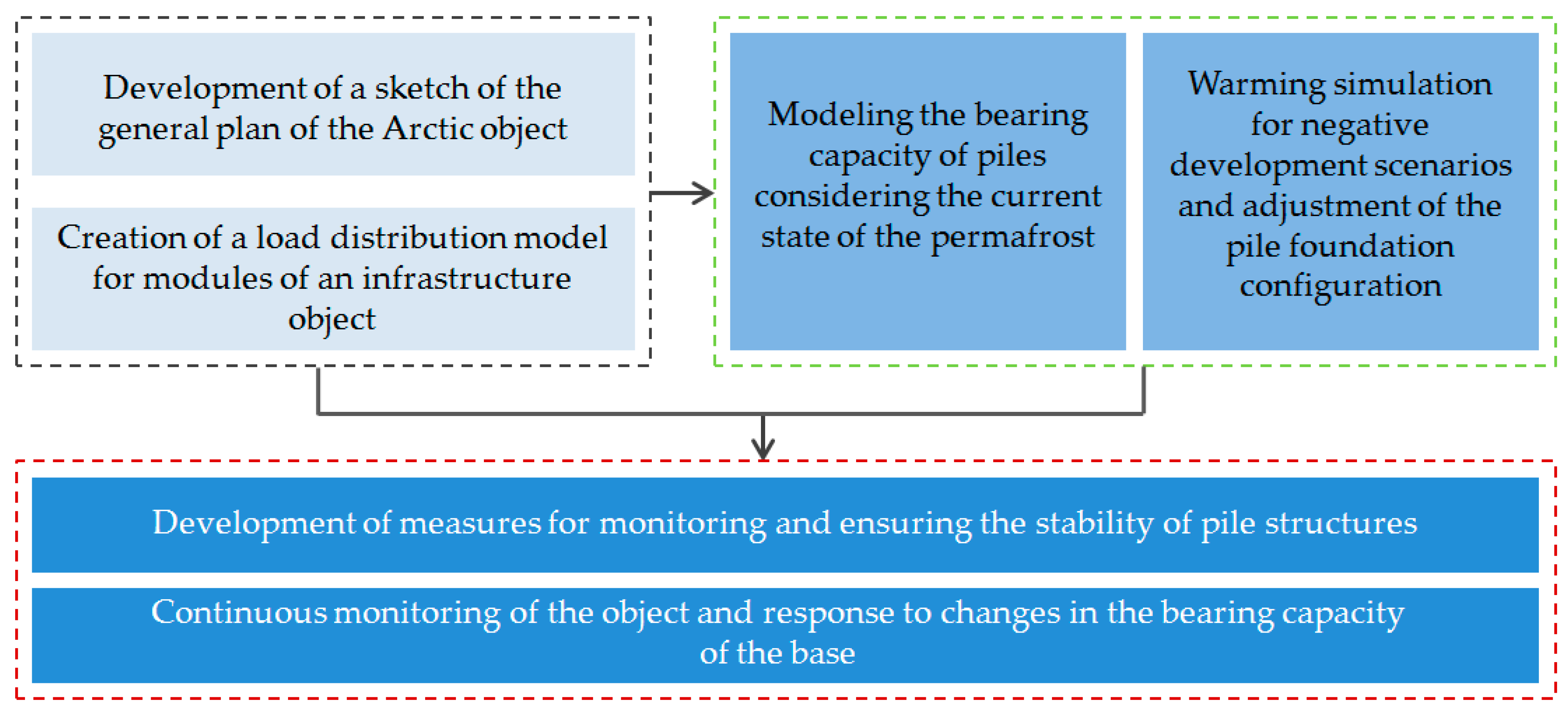
  • determination of the list of necessary initial data for modeling the bearing capacity of piles for individual modules (taking into account concentrated and distributed loads on the pile foundation);
  • development of a sketch of the general plan of the object.
The 2nd block is the modeling stage:
  • modeling of bearing capacity and selection of characteristics of pile fields (type of pile and its geometric characteristics, distance between piles and method of installation) according to engineering survey data;
  • modeling of thawing of frozen soils with different dynamics of changes in average annual temperatures.
The final block includes:
  • selection of a list of measures to preserve the bearing capacity of piles, depending on the results presented in the second block;
  • year-round monitoring of the stability of the facility during the entire period of its operation.
To ensure the stability of the pile foundations of remote industrial Arctic objects, it is proposed to carry out modeling of heat transfer processes in order to predict the rate of thawing of permafrost, taking into account climate change. In case of revealing a significant loss of the bearing capacity of the piles, the design documentation should be adjusted taking into account negative scenarios. During the operation of the pile foundation, it is necessary to monitor the bearing capacity of the piles and respond in a timely manner to changes occurring in the cryolitic zone.

5. Conclusions

Global climate change poses new challenges to the industry involved in the development of mineral reserves in the Arctic regions. Civil and industrial structures designed and built without taking into account the warming factor begin to collapse due to changes in the structure of permafrost. The situation may be aggravated by the rising level of the world ocean, leading to an increase in the area of flooded Arctic territories. Mining University is developing technical and technological solutions for the construction of remote Arctic facilities and a methodology for their design based on physical and mathematical predictive modeling [51]. The solutions proposed by the authors will make it possible to ensure the sustainability of infrastructure facilities in remote Arctic territories.

Author Contributions

Conceptualization, G.B., P.T.; methodology, A.K. and D.S.; software, A.L. and E.L.; validation, A.K. and D.S.; formal analysis, G.B.; investigation, A.K., D.S. and A.L.; resources, P.T.; data curation, G.B.; writing—original draft preparation, A.K. and D.S.; writing—review and editing, A.L., D.S. and A.K.; visualization, E.L. and A.L.; supervision, G.B.; project administration, G.B.; funding acquisition, P.T. All authors have read and agreed to the published version of the manuscript.

Funding

The framework for the sustainable development of Arctic facilities was created with the financial support of the grant by the President of the Russian Federation for the state support of leading scientific schools of the Russian Federation, the number of the project NSh-2692.2020.5 “Modelling of ecological-balanced and economically sustainable development of hydrocarbon resources of the Arctic”.

Data Availability Statement

The data presented in this study are available on request from the corresponding author.

Acknowledgments

The framework for the sustainable development of Arctic facilities was created with the financial support of the grant by the President of the Russian Federation for the state support of leading scientific schools of the Russian Federation, the number of the project NSh-2692.2020.5 “Modelling of ecological-balanced and economically sustainable development of hydrocarbon resources of the Arctic”.

Conflicts of Interest

The authors declare no conflict of interest.

References

  1. Zhukovskiy, Y.; Tsvetkov, P.; Buldysko, A.; Malkova, Y.; Stoianova, A.; Koshenkova, A. Scenario Modeling of Sustainable Development of Energy Supply in the Arctic. Resources 2021, 10, 124. [Google Scholar] [CrossRef]
  2. The Intergovernmental Panel on Climate Change. Global Warming of 1.5 C. Available online: www.ipcc.ch (accessed on 23 November 2021).
  3. Masson-Delmotte, V.; Zhai, P.; Pörtner, H.-O.; Roberts, D.; Skea, J.; Shukla, P.R.; Pirani, A.; Moufouma-Okia, W.; Péan, C.; Pidcock, R.; et al. IPCC Special Report: Global Warming of 1.5 C—Summary for Policymakers; World Meteorological Organization: Geneva, Switzerland, 2018; 32p.
  4. Stocker, T.F.; Qin, D.; Plattner, G.-K.; Tignor, M.; Allen, S.K.; Boschung, J.; Nauels, A.; Xia, Y.; Bex, V.; Midgley, P.M. IPCC. Summary for Policymakers. In Climate Change 2013: The Physical Science Basis. Contribution of Working Group I to the Fifth Assessment Report of the Intergovernmental Panel on Climate Change; Cambridge University Press: Cambridge, UK; New York, NY, USA, 2013; 28p, Available online: http://www.ipcc.ch/pdf/assessment-report/ar5/wg1/WG1AR5_SPM_FINAL.pdf (accessed on 23 November 2021).
  5. Meinshausen, M.; Smith, S.J.; Calvin, K.; Daniel, J.S.; Kainuma, M.L.T.; Lamarque, J.F.; Matsumoto, K.; Montzka, S.A.; Raper, S.C.B.; Riahi, K.; et al. The RCP greenhouse gas concentrations and their extensions from 1765 to 2300. Clim. Chang. 2011, 109, 213–241. [Google Scholar] [CrossRef] [Green Version]
  6. Le Quéré, C.; Andrew, R.M.; Friedlingstein, P.; Sitch, S.; Hauck, J.; Pongratz, J.; Pickers, P.A.; Korsbakken, J.I.; Peters, G.P.; Canadell, J.G.; et al. Global Carbon Budget 2018. Earth Syst. Sci. Data 2018, 10, 2141–2194. [Google Scholar] [CrossRef] [Green Version]
  7. Biskaborn, B.K.; Smith, S.L.; Noetzli, J.; Matthes, H.; Vieira, G.; Streletskiy, D.A.; Schoeneich, P.; Romanovsky, V.E.; Lewkowicz, A.G.; Abramov, A.; et al. Permafrost is warming at a global scale. Nat. Commun. 2019, 10, 264. [Google Scholar] [CrossRef] [Green Version]
  8. Rajendran, S.; Sadooni, F.N.; Al-Kuwari, H.A.-S.; Oleg, A.; Govil, H.; Nasir, S.; Vethamony, P. Monitoring oil spill in Norilsk, Russia using satellite data. Sci. Rep. 2021, 11, 3817. [Google Scholar] [CrossRef]
  9. Meredith, M.; Sommerkorn, M.; Cassotta, S.; Derksen, C.; Ekaykin, A.; Hollowed, A.; Kofinas, G.; Mackintosh, A.; Melbourne-Thomas, J.; Muelbert, M.M.C.; et al. Chapter 3: Polar regions. In The Ocean and Cryosphere in a Changing Climate: Summary for Policymakers; Intergovernmental Panel on Climate Change; 2019; pp. 3-1–3-173. Available online: https://www.ipcc.ch/srocc/chapter/chapter-3-2/ (accessed on 23 November 2021).
  10. Moon, T.A.; Overeem, I.; Druckenmiller, M.; Holland, M.; Huntington, H.; Kling, G.; Lovecraft, A.L.; Miller, G.; Scambos, T.; Schädel, C.; et al. The expanding footprint of rapid Arctic change. Earths Future 2019, 7, 212–218. [Google Scholar] [CrossRef] [Green Version]
  11. Koven, C.D.; Ringeval, B.; Friedlingstein, P.; Ciais, P.; Cadule, P.; Khvorostyanov, D.; Krinner, G.; Tarnocai, C. Permafrost carbon-climate feedbacks accelerate global warming. Proc. Natl. Acad. Sci. USA 2011, 108, 14769–14774. [Google Scholar] [CrossRef] [Green Version]
  12. Timofeev, A.V.; Piirainen, V.Y.; Bazhin, V.Y.; Titov, A.B. Operational Analysis and Medium-Term Forecasting of the Greenhouse Gas Generation Intensity in the Cryolithozone. Atmosphere 2021, 12, 1466. [Google Scholar] [CrossRef]
  13. Vincent, W.F. Arctic Climate Change: Local Impacts, Global Consequences, and Policy Implications. In The Palgrave Handbook of Arctic Policy and Politics; Springer International Publishing: Cham, Switzerland, 2020. [Google Scholar]
  14. Pörtner, H.-O.; Roberts, D.C.; Masson-Delmotte, V.; Zhai, P.; Tignor, M.; Poloczanska, E.; Mintenbeck, K.; Alegría, A.; Nicolai, M.; Okem, A.; et al. Summary for Policymakers. In IPCC Special Report on the Ocean and Cryosphere in a Changing Climate; 2019; Available online: https://www.ipcc.ch/site/assets/uploads/sites/3/2019/11/03_SROCC_SPM_FINAL.pdf (accessed on 23 November 2021).
  15. Church, J.A.; White, N.J. Sea-Level Rise from the Late 19th to the Early 21st Century. Surv. Geophys. 2011, 32, 585–602. [Google Scholar] [CrossRef] [Green Version]
  16. Domingues, R.; Goni, G.; Baringer, M.; Volkov, D. What Caused the Accelerated Sea Level Changes along the U.S. East Coast during 2010–2015. Geophys. Res. Lett. 2018, 45, 13367–13376. [Google Scholar] [CrossRef]
  17. Leuliette, E. The Budget of Recent Global Sea Level Rise 2005–2013; National Oceanic and Atmospheric Administration: Washington, DC, USA, 2014. Available online: https://www.star.nesdis.noaa.gov/socd/lsa/SeaLevelRise/documents/NOAA_NESDIS_Sea_Level_Rise_Budget_Report_2014.pdf (accessed on 23 November 2021).
  18. Sweet, W.V.; Kopp, R.E.; Weaver, C.P.; Obeysekera, T.; Horton, R.M.; Thieler, E.R.; Zervas, C. Global and Regional Sea Level Rise Scenarios for the United States. In NOAA Technical Report NOS CO-OPS 083; National Oceanic and Atmospheric Administration: Washington, DC, USA, 2017; 75p. Available online: https://tidesandcurrents.noaa.gov/publications/techrpt83_Global_and_Regional_SLR_Scenarios_for_the_US_final.pdf (accessed on 23 November 2021).
  19. Sweet, W.V.; Park, J.; Marra, J.J.; Zervas, C.; Gill, S. Sea level rise and nuisance flood frequency changes around the U.S. In NOAA Technical Report NOS CO-OPS 73; National Oceanic and Atmospheric Administration: Washington, DC, USA, 2014; 53p. Available online: https://tidesandcurrents.noaa.gov/publications/NOAA_Technical_Report_NOS_COOPS_073.pdf (accessed on 23 November 2021).
  20. Church, J.A.; Clark, P.U.; Cazenave, A. Sea Level Change. CUP 2013, 13, 1137–1216. [Google Scholar]
  21. Romasheva, N.; Dmitrieva, D. Energy Resources Exploitation in the Russian Arctic: Challenges and Prospects for the Sustainable Development of the Ecosystem. Energies 2021, 14, 8300. [Google Scholar] [CrossRef]
  22. Tcvetkov, P.; Cherepovitsyn, A.; Makhovikov, A. Economic assessment of heat and power generation from small-scale liquefied natural gas in Russia. Energy Rep. 2020, 6, 391–402. [Google Scholar] [CrossRef]
  23. Tretyakov, N.; Cherepovitsyn, A.; Komendantova, N. Technology predictions for arctic hydrocarbon development: Digitalization potential, 5th International Conference on Technological Transformation: A New Role for Human, Machines and Management. Technol. Transform. 2020, 157, 241–251. [Google Scholar] [CrossRef]
  24. Dmitrieva, D.; Romasheva, N. Sustainable Development of Oil and Gas Potential of the Arctic and Its Shelf Zone: The Role of Innovations. J. Mar. Sci. Eng. 2020, 8, 1003. [Google Scholar] [CrossRef]
  25. Carayannis, E.G.; Ilinova, A.; Cherepovitsyn, A. The Future of Energy and the Case of the Arctic Offshore: The Role of Strategic Management. J. Mar. Sci. Eng. 2021, 9, 134. [Google Scholar] [CrossRef]
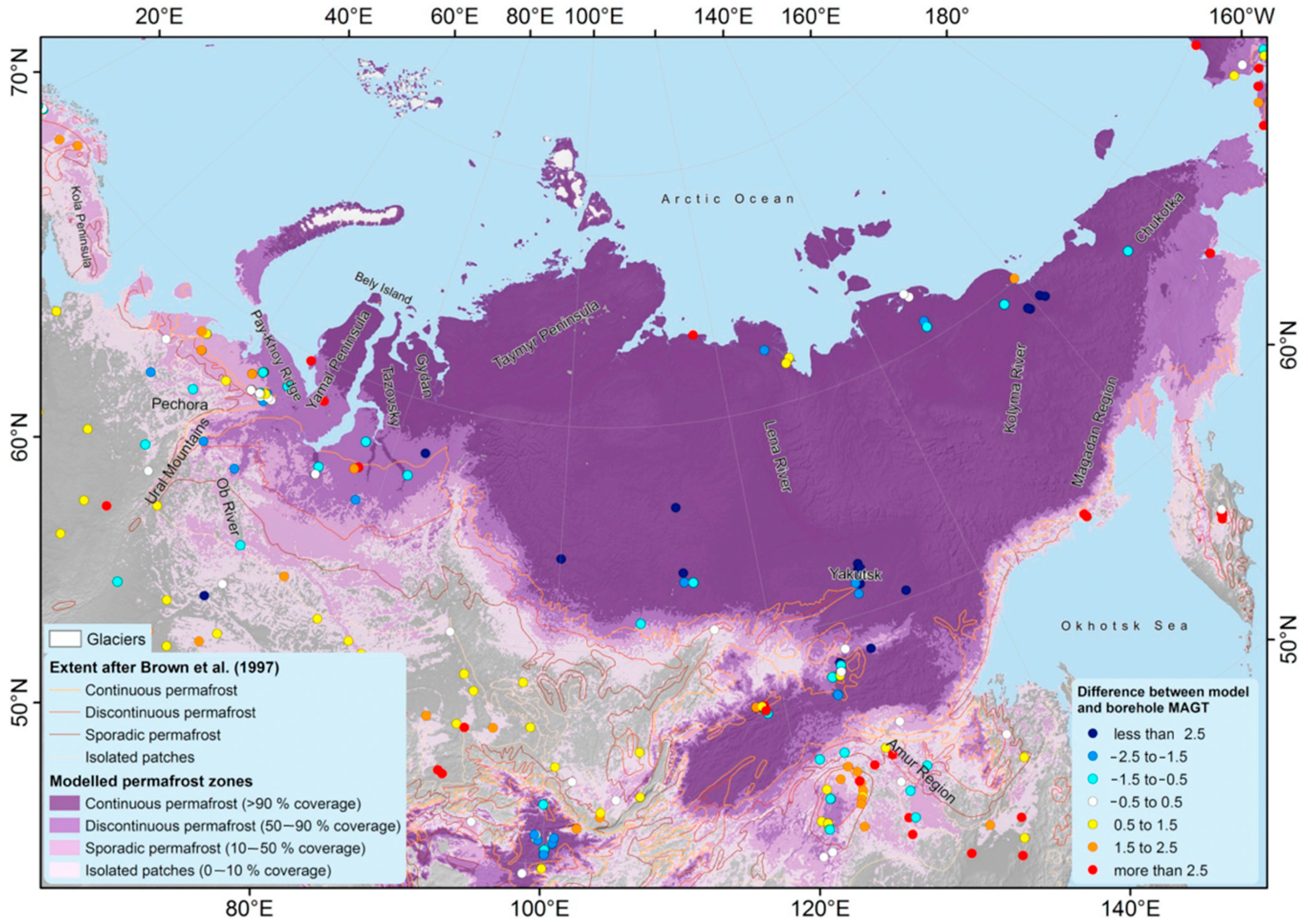
  26. Obu, J.; Westermann, S.; Bartsch, A.; Berdnikov, N.; Christiansen, H.H.; Dashtseren, A.; Zou, D. Northern Hemisphere permafrost map based on TTOP modelling for 2000–2016 at 1 km2 scale. Earth Sci. Rev. 2019, 193, 300–316. [Google Scholar] [CrossRef]
  27. Tokarev, I.V. Use of isotope data (δ2H, δ18O, 234U/238U) in the study of permafrost degradation processes as a result of long-term climate variations. J. Min. Inst. 2008, 176, 191. [Google Scholar]
  28. Vasiliev, G.G.; Dzhaljabov, A.A.; Leonovich, I.A. Analysis of the causes of engineering structures deformations at gas industry facilities in the permafrost zone. J. Min. Inst. 2021, 249, 377–385. [Google Scholar] [CrossRef]
  29. Vernigor, V.M.; Morozov, K.V.; Bobrovnikov, V.N. On approaches to designing of thermal regime at ore mines under permafrost conditions. J. Min. Inst. 2013, 205, 139–140. [Google Scholar]
  30. Potapov, A.I.; Pavlov, I.V. Acoustic emission diagnostics buildings mining companies in the North. J. Min. Inst. 2014, 209, 128–132. [Google Scholar]
  31. Vasiltsov, V.S.; Vasiltsova, V.M. Strategic planning of arctic shelf development using fractal theory tools. J. Min. Inst. 2018, 234, 663. [Google Scholar] [CrossRef]
  32. Mangushev, R.; Sakharov, I. Foundations and Foundations: Textbook for Bachelors of Construction and Specialists in the Field of Construction of Unique Buildings and Structures; Publishing house ASV: Moscow, Russia, 2019; 468p. [Google Scholar]
  33. Jorgenson, M.T.; Grosse, G. Remote Sensing of Landscape Change in Permafrost Regions. Permafr. Periglac. Process. 2016, 27, 324–338. [Google Scholar] [CrossRef]
  34. Korobkov, G.E.; Yanchushka, A.P.; Zakiryanov, M.V. Numerical modeling of a stress-strain state of a gas pipeline with cold bending offsets according to in-line inspection. J. Min. Inst. 2018, 234, 643. [Google Scholar] [CrossRef]
  35. Islamov, S.; Grigoriev, A.; Beloglazov, I.; Savchenkov, S.; Gudmestad, O.T. Research Risk Factors in Monitoring Well Drilling—A Case Study Using Machine Learning Methods. Symmetry 2021, 13, 1293. [Google Scholar] [CrossRef]
  36. Litvinenko, V.S.; Trushko, V.L.; Dvoinikov, M.V. Method of Ice-Resistant Drilling Platform Construction on Shallow Shelf of Arctic Seas. Patent for Invention RU 273739, 27 November 2020. [Google Scholar]
  37. Litvinenko, V.S.; Trushko, V.L.; Dvoinikov, M.V. Method for the Construction of an Offshore Drilling Platform on the Shallow Shelf of the Arctic Seas. Patent for Invention RU 2704451, 28 October 2019. [Google Scholar]
  38. Litvinenko, V.S.; Trushko, V.L.; Dvoinikov, M.V. Elaboration of a conceptual solution for the development of the Arctic shelf from seasonally flooded coastal areas. Int. J. Min. Sci. Technol. 2021. [Google Scholar] [CrossRef]
  39. Set of Rules SP 25.13330.2020. Bottoms and Foundations on Permafrost Soils; Standartinform: Moscow, Russia, 2020; Approved by Order of the Ministry of Construction and Housing and Communal Services of the Russian Federation No. 915/pr.
  40. Weismüller, J.; Wollschläger, U.; Boike, J.; Pan, X.; Yu, Q.; Roth, K. Modeling the thermal dynamics of the active layer at two contrasting permafrost sites on Svalbard and on the Tibetan Plateau. Cryosphere 2011, 5, 741–757. [Google Scholar] [CrossRef] [Green Version]
  41. Kane, D.; Hinkel, K.; Goerin, D.; Hinzman, L.; Outcalt, S. Non-conductive heat transfer associated with frozen soils. Glob. Planet Chang. 2001, 29, 275–292. [Google Scholar] [CrossRef]
  42. Liu, G.; Xie, C.; Zhao, L.; Xiao, Y.; Wu, T.; Wang, W.; Liu, W. Permafrost warming near the northern limit of permafrost on the Qinghai–Tibetan Plateau during the period from 2005 to 2017: A case study in the Xidatan area. Permafr. Periglac. Process. 2020, 32, 323–334. [Google Scholar] [CrossRef]
  43. Liu, G.; Wu, T.; Hu, G.; Wu, X.; Li, W. Permafrost existence is closely associated with soil organic matter preservation: Evidence from relationships among environmental factors and soil carbon in a permafrost boundary area. Catena 2021, 196, 104894. [Google Scholar] [CrossRef]
  44. Andreyev, M.A.; Andreev, I.A.; Mironov, A.V.; Terentyev, M.A. Arrangement of bases and foundations of oil reservoirs in complicated conditions of Polar region. Ind. Civ. Eng. 2006, 9, 40–41. [Google Scholar]
  45. Svetlov, L.P.; Vedrashko, E.M.; Voronoj, V.A.; Biryukov, O.R.; Ozornin, A.A.; Letin, E.V. Method of Forced Reduction of Permafrost Soil Temperature in the Bases of Pile Foundations of the Operating Bridge Supports. Patent for the Invention RU 2731343, 1 September 2020. [Google Scholar]
  46. Bocharov, A.G.; Bocharov, M.E.; Kozhevnikov, S.A. Method of Cold Accumulation in the Ground. Patent for the Invention RU 2650005, 6 April 2018. [Google Scholar]
  47. Prokopenko, I.F.; Shtefanov, Y.P.; Shishov, I.N. Year-round thermal stabilization of a building. In Proceedings of the Fifth Conference of Russian Geocryologists, Moscow, Russia, 14–17 June 2016; pp. 291–296. (In Russian). [Google Scholar]
  48. Trushevsky, S.N.; Strebkov, D.S. Method and Device for Year-Round Cooling, Freezing of Foundation Soil and Heat Supply of Structures on Permafrost Soil in Cryolithozone Conditions. Patent for the Invention RU 2519012, 10 June 2014. [Google Scholar]
  49. Lavrik, A.Y.; Buslaev, G.V.; Dvoinikov, M.V.; Zhukovsky, Y.L. Method of Combined Year-Round Temperature Stabilization of Soil. Application for the Invention RU 2021109950, 12 April 2021. [Google Scholar]
  50. Dvoynikov, M.; Buslaev, G.; Kunshin, A.; Sidorov, D.; Kraslawski, A.; Budovskaya, M. New Concepts of Hydrogen Production and Storage in Arctic Region. Resources 2021, 10, 3. [Google Scholar] [CrossRef]
  51. Litvinenko, V.S.; Leitchenkov, G.L.; Vasiliev, N.I. Anticipated sub-bottom geology of Lake Vostok and technological approaches considered for sampling. Chem. Erde/Geochem. 2020, 80, 125556. [Google Scholar] [CrossRef]
Figure 1. Historical observations and projections from RTK2.6 and RTK8.5 for near-surface permafrost [14].
Resources 10 00128 g001
Figure 2. Global Permafrost zonation for Russia [26].
Resources 10 00128 g002
Figure 3. Prototyping of production infrastructure facilities on a pile foundation.
Resources 10 00128 g003
Figure 4. The modular pile base of a drilling rig. (a) for exploration drilling, (b) for production drilling.
Resources 10 00128 g004
Figure 5. Functional diagram of an autonomous thermal stabilization unit with a thermosiphon and a refrigerating machine powered by renewable energy sources and energy storage system inside the heated container [49].
Resources 10 00128 g005
Figure 6. Annual graph of monthly averaged capacity of thermosyphon without application of jet grouting technology.
Resources 10 00128 g006
Figure 7. Temperature distribution for 2050 under a positive warming scenario.
Resources 10 00128 g007
Figure 8. Temperature distribution for 2050 under a neutral warming scenario.
Resources 10 00128 g008
Figure 9. Temperature distribution for the year 2050 under a negative scenario of warming.
Resources 10 00128 g009
Figure 10. Temperature distribution for 2050 under a local negative warming scenario.
Resources 10 00128 g010
Figure 11. Modeling results of the winter ground temperature distribution.
Resources 10 00128 g011
Figure 12. Modeling results of ground temperature distribution in the summer period.
Resources 10 00128 g012
Figure 13. The proposed methodology for pile foundation design on a base.
Resources 10 00128 g013
Table 1. Soil characteristics for modeling the bearing capacity of foundations.
LayerType of SoilsCut Open Thickness, mDensity of Dry Soil ρd, g/cm3Total Humidity
Wtot, d.e.
Layer-1Brown peat, malleable, highly porous0.50.144.82
Layer-2Sand, fine, solid frozen3.51.580.23
Layer-3Clay loam, dark gray hard frozen4.51.260.31
Layer-4Sandy silt7.01.560.24
Table 2. Air temperature and wind speed (average monthly and annual data).
Air Temperature, °C
IIIIIIIVVVIVIIVIIIIXXXIXIIper Year
−23.1−24.6−20.4−15.3−6.8−0.76.05.82.6−5.8−14.0−18.7−9.5
Wind Speed, m/s
IIIIIIIVVVIVIIVIIIIXXXIXIIper Year
6.46.26.36.06.35.95.45.86.46.86.87.06.3
Table 3. Results of modeling the bearing capacity of the soil for various scenarios.
Characteristics of PilesWarming ScenarioIncrease of Temperature per Year, °CActive Layer by 08.2050, mPile Bearing Capacity as of 08.2050, tons
L = 8 m,
Ø = 0.2 m
Positive0.110.59581.93
Neutral0.160.67375.84
Negative0.240.84071.32
Locally negative0.501.86863.79
Publisher’s Note: MDPI stays neutral with regard to jurisdictional claims in published maps and institutional affiliations.

