Review

New Concepts of Hydrogen Production and Storage in Arctic Region

1
Arctic Competence Center, Saint Petersburg Mining University, 199106 Saint Petersburg, Russia
2
School of Engineering Science, Lappeenranta-Lahti University of Technology, FI-53851 Lappeenranta, Finland
3
Faculty of Process and Environmental Engineering, Lodz University of Technology, 90-924 Lodz, Poland
*
Author to whom correspondence should be addressed.
Resources 2021, 10(1), 3; https://doi.org/10.3390/resources10010003
Submission received: 23 November 2020 / Revised: 3 January 2021 / Accepted: 4 January 2021 / Published: 7 January 2021
(This article belongs to the Special Issue Resource Provision of the Sustainable Development under Global Shocks)

Abstract

:
The development of markets for low-carbon energy sources requires reconsideration of issues related to extraction and use of oil and gas. Significant reserves of hydrocarbons are concentrated in Arctic territories, e.g., 30% of the world’s undiscovered natural gas reserves and 13% of oil. Associated petroleum gas, natural gas and gas condensate could be able to expand the scope of their applications. Natural gas is the main raw material for the production of hydrogen and ammonia, which are considered promising primary energy resources of the future, the oxidation of which does not release CO2. Complex components contained in associated petroleum gas and gas condensate are valuable chemical raw materials to be used in a wide range of applications. This article presents conceptual Gas-To-Chem solutions for the development of Arctic oil and gas condensate fields, taking into account the current trends to reduce the carbon footprint of products, the formation of commodity exchanges for gas chemistry products, as well as the course towards the creation of hydrogen energy. The concept is based on modern gas chemical technologies with an emphasis on the production of products with high added value and low carbon footprint.

1. Introduction

Despite the existing trends of transition to renewable energy, a complete elimination of hydrocarbon raw materials is not possible in a near perspective because of constant growth of energy consumption. Simultaneously, the problem of climate change, especially in Arctic and other ecologically fragile regions, starts to be more and more acute [1,2].
Therefore, use of hydrogen starts to attract attention as an alternative way to reduce greenhouse gas emissions [3]. The European Union (EU) prognosis to create a hydrogen economy recognizes the limits in satisfying the EU’s demand for low-carbon hydrogen on the basis of its own renewable energy resources [4]. Therefore, supply from external sources is considered to be a viable option. On the other hand, according to Energy Strategy of the Russian Federation for the period up to 2035, it is planned to export 0.2 million tons by 2024, and by 2035, 2 million tons of hydrogen [5].
The growing interest in the use of hydrogen has attracted attention to a need of classification of its origin and production methods. It is motivated by the fact that different methods of hydrogen production have their own specific carbon and toxic footprint. One of the attempts to build a taxonomy is the color classification [6]. The following colors of hydrogen are identified:
Green hydrogen—produced by electrolysis of water, while electrolysis uses only electricity from renewable energy sources. Regardless of the electrolysis technology chosen, the production of hydrogen has no carbon footprint, as 100% of the energy must come from renewable sources.
Gray hydrogen—produced from fossil fuels, typically natural gas. It produces waste gases containing CO2 and increases the global greenhouse effect. The production of one ton of hydrogen in this way produces about 10 tons of CO2.
Blue hydrogen—like gray hydrogen, but during the production process CO2 must be separated and buried (Carbon Capture and Storage, CCS) or used for the production of fuels or chemical raw materials (Carbon Capture and Utilization, CCU) [7,8].
Turquoise hydrogen—produced by the thermal decomposition of natural gas (methane pyrolysis). Instead of CO2, the process releases solid carbon (soot). At the same time, the use of renewable energy for the operation of a high-temperature reactor, as well as the long-term binding or storage of solid carbon, is a necessary condition for the CO2-neutrality of the process.
In the future, gray hydrogen will not be used at all due to its highest carbon footprint. The potential for obtaining green hydrogen is limited due to high energy consumption in the process of water electrolysis.
The cost of turquoise hydrogen obtained by pyrolysis of methane, according to experts in the field of simulation and computer modeling, is much lower than that of hydrogen produced by electrolysis of water (green hydrogen). This is due to the fact that part of the energy is lost due to the efficiency of the electrolyzer 70–80%. Whereas pyrolysis of methane requires several times less energy than electrolysis. In addition, water used in electrolysis has no free energy, whereas methane has the potential to release energy during oxidation. When separating a methane molecule, hydrogen has a greater energy potential for further oxidation than that the energy spent on pyrolysis. In this case, the cost of hydrogen will depend on the cost of gas, which is minimal in the places of its production. According to our preliminary estimates, the cost of turquoise hydrogen may be lower than the cost of hydrogen produced by traditional steam reforming of natural gas with the capture of greenhouse gases (blue hydrogen). This is due to the fact that there is no need to build and maintain a CSS and CCU infrastructure for turquoise hydrogen.
The growing demand of European countries for hydrogen could create an opportunity for hydrogen production in the Russian Arctic region and its transport using new trunk pipelines. However, it should be noted that building trunk pipelines for transportation of pure hydrogen is economically unprofitable due to the high capital (use of special types of steels and coatings) and operating costs of installing and maintaining the infrastructure. The use of the existing gas transportation infrastructure is possible only when natural gas is transported with the addition of maximum 20% of hydrogen. These circumstances require the rebuilding of existing gas transportation infrastructure or the use of other means of transport [9].
The above-mentioned limitations related to production and transport of hydrogen lead to the idea of situating hydrogen production in an area with a nearby well-established transport system, and not to build transport infrastructure of remote green field. The Northern Sea Route for transportation of the Russian Federation production to the countries of Western Europe and the Asia-Pacific region, Figure 1, is considered as a perspective due to the following factors [10]:
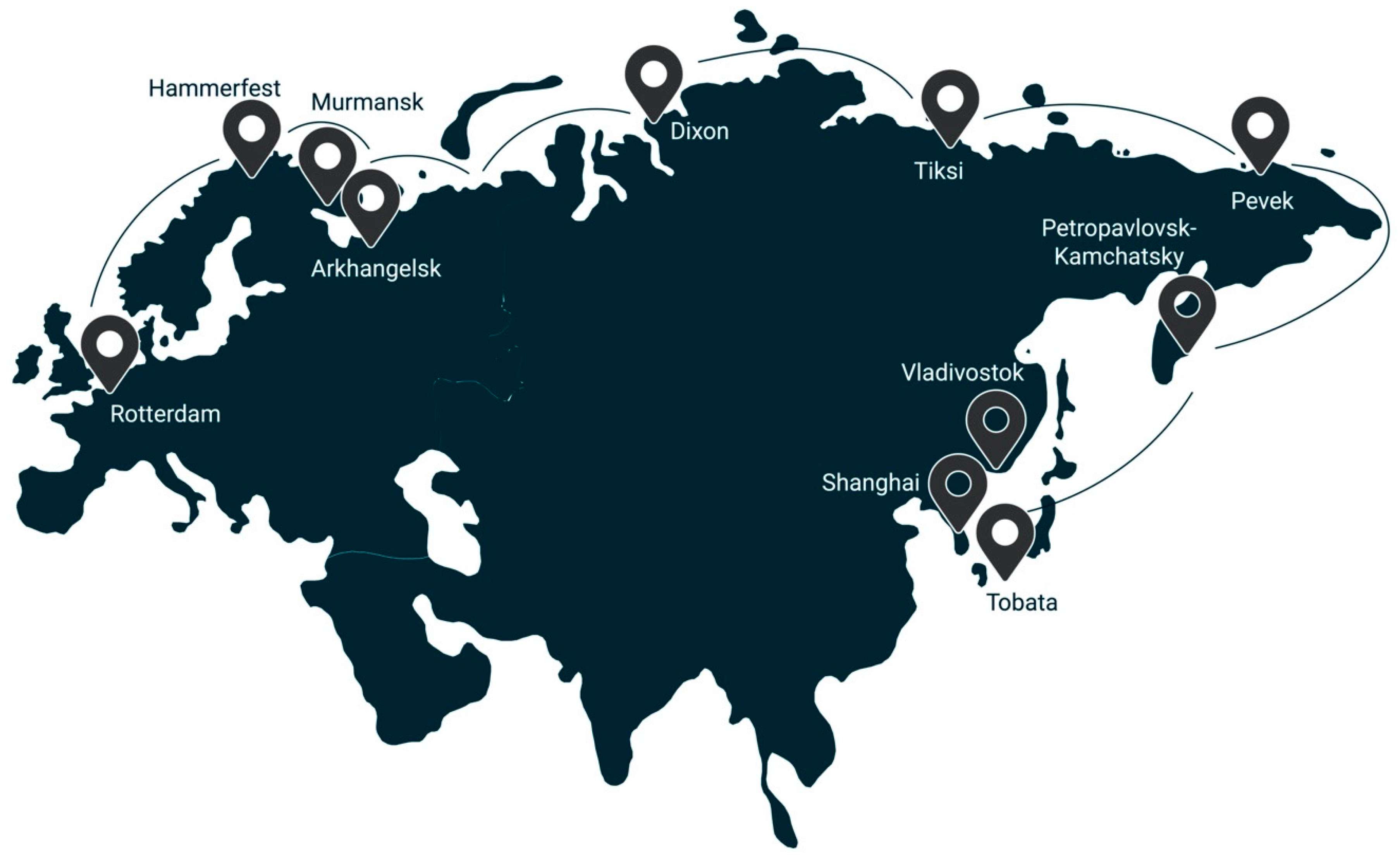
  • The presence of the Northern Sea route (product-distribution routes, both to the countries of the EU and to the countries of the Asia-Pacific region);
  • possibility of bound hydrogen transport in a solid form using dry cargo vessels and in liquid form by tankers.
In consideration of the foregoing, the task of considering new concepts for the production, storage and transport of hydrogen at the facilities of the Arctic region corresponds to actual global needs.
For this, the article attempts to revise the existing approaches to the development of Arctic oil, gas and gas condensate fields in order to focus on the emerging markets for low-carbon products.
First of all, we will consider promising methods of hydrogen production that can be integrated into Arctic industrial production.

2. Promising Methods of Hydrogen Production

More than 100 existing and proposed technologies for the production of hydrogen are described [11,12]. More than 80% of the described technologies are based on the steam conversion of fossil fuels and over 70% among them on the conversion of natural gas. However, to reduce carbon dioxide emissions from remote Arctic oil and gas facilities, a broader range of hydrogen production technologies needs to be considered, including methane pyrolysis and seawater electrolysis using renewable energy sources.

2.1. Blue Hydrogen

The main industrial technology for hydrogen production is steam methane reforming (SMR) [13,14]. The autothermal reforming (ATR) is the most common production method [14,15,16,17,18,19]. Also popular is dry reforming of methane (DRM), partial oxidation (POX) and their combinations.
In recent years, the technology of production and purification of synthesis gas has attracted much attention from both researchers and industry [19]. Since its development, it has become one of the main directions for more efficient, sustainable and environmentally safe use of hydrocarbon resources.
The reference [17] presents the topic of hydrogen-based fuel cells and energy, and addresses important trends in the contemporary energy industry, in particular, how to integrate fuel reprocessing into modern systems.
According to [16], it is important to remember that the route of hydrogen production and the choice of a specific technology depends on the type of energy and available raw materials, as well as on the required purity of the final product.
POX technologies were originally proposed by Texaco and Shell [17,18]. They are widely used in industry, and at present there are over 300 operating installations [11].
In Russia, many research centers have carried out theoretical and experimental investigations of the process of hydrocarbon partial oxidation [18,20]. However, there are no industrial POX installations. The source [20] describes in detail a method for producing synthesis gas for low-tonnage methanol production based on partial oxidation of natural gas in original three-component (hydrocarbon feedstock—oxidizer—water) synthesis gas generators (SGG) (hydrogen, carbon monoxide and carbon dioxide, water steam and ballast gases).
To carry out POX, it is possible to use chemical reactors based on power plants with high productivity and relatively low energy consumption for conversion and small weight and size characteristics. It favorably distinguishes them from any other partial oxidation devices [18,20,21]. The source [21] considers the physical model and the design of the SGG. A method for calculating the nominal geometric dimensions of the SGG is proposed, which makes it possible to assess the mass and size characteristics of the SGG already at the stage of implementation of the basic project.
The recent research [22] found that in the case of synthesis gas production by POX of natural or associated petroleum gas, the estimated cost of hydrogen production is 1.33 euros/kg H2. The cost of large-scale production of H2 varies from 1 to 1.5 euro/kg H2. It is worth remembering that the decision on the economic feasibility of using natural or associated petroleum gases for the production of H2 should be made in the context of transport infrastructure or the use of hydrogen directly at the site of oil or gas production.

2.2. Turquoise Hydrogen

Thermal or thermocatalytic decomposition (cracking or pyrolysis) is one of the methods to produce hydrogen with a low carbon footprint. The reaction of splitting methane molecules into hydrogen and carbon is carried out in a pyrolysis reactor at temperature from 600 to 1200–1400 °C [23]. Many studies are devoted to the search of effective catalysts in pyrolysis. However, the problem of catalyst deactivation, highlighted in these studies, cannot be solved by burning carbon from the catalyst surface, since in this case CO2 emissions become comparable to the emissions in steam reforming of methane [24]. The problem of coking is less acute when using carbon catalysts—activated and black carbon, graphite, nanostructured carbon, etc. [25,26,27]. In this case, the reactor contains a fluidized bed with carbon catalyst particles [24]. However, all catalysts are subject to deactivation, and the formation of solid carbon as a product can lead to reactor fouling [28]. Another method of methane pyrolysis is the removal of these disadvantages thanks to the use of molten metal as a heat carrier and a bubble column for the extraction of solid carbon and gaseous hydrogen. In addition, the produced carbon, as well as the liquid metal, can act as a catalyst for the process [29]. As a rule, Sn [15,29] and Pb [17] are used as molten metal; however, there are studies aimed at finding new materials, e.g., Ni-Bi melt is proposed in [16]. Ni-Bi melt possesses catalytic properties capable of increasing methane conversion, in contrast to non-catalytic Sn and Pb melt [13,30,31,32,33,34,35,36,37,38,39]. The effect of temperature on the direct cracking of methane was studied in [30]. This research confirmed that the accumulation of carbon black in the reaction tube is the main technological obstacle in the implementation of the process of direct thermal cracking of methane. There were also studies on the types of catalysts used for methane cracking in order to reduce the amount of carbon dioxide generated in hydrogen production from methane [32,35]. The thermochemical model for the assessment of factors influencing the process of obtaining hydrogen by pyrolysis of methane was presented in [34]. It was discovered that the temperature and residence time of the gas have the greatest impact on the yield of methane conversion. It was also confirmed in [37,38]. In [37,39] there was analyzed the process of thermocatalytic decomposition of methane in a fluidized bed reactor aimed at reducing the amount of harmful emissions.
According to preliminary modeling, hydrogen with a negative carbon footprint can be produced by pyrolysis of biogas, in which carbon has been captured naturally from the air during biomass formation. In addition, it is assumed that solid carbon produced by pyrolysis of methane can be used for the production of nanostructured materials such as carbon nanotubes and fullerenes [40]. At present, the high cost of such materials limits their broad use, e.g., in the construction of highways or cement production.

2.3. Green Hydrogen

The electrolysis of water is also a common method of hydrogen production. The electrochemical dissociation of water into oxygen and hydrogen was studied in [41]. Based on recent research, low-temperature electrolysis is used to produce hydrogen. It allows to store electricity from renewable sources in chemical bonds in the form of high-purity H2 [42]. Low-temperature electrolysis of water uses a concentrated potassium hydroxide solution KOH, a proton exchange membrane (PEM), or an alkaline anion exchange membrane (AEM) as an electrolyte. The main advantage of AEM electrolysis over other options is its cost as in this case there is no need to use platinum group metals (PGM) as catalysts. However, the major difficulty is the instability of the alkaline method, due to the sensitivity to pressure drop and the low rate of hydrogen production [43]. A traditional electrolysis device consists of two metal electrodes, an anode and a cathode, placed in an electrolyte solution and separated by a membrane [44]. When a current passes through the solution, oxygen bubbles rise above the anode and hydrogen bubbles above the cathode. To minimize the amount of energy required to liberate hydrogen from water, both electrodes are usually coated with a catalyst. However, to produce hydrogen, significant volumes of fresh water will be required, the reserves of which are already limited. The solution of this problem would be the conversion of seawater.
The seawater is mainly a mixture of Cl and Na ions. Unfortunately, Cl ions cause corrosion of the anode metal and prevent the production of hydrogen. To overcome this problem, the anode is designed as a porous nickel foam pan collector coated with an active and cheap nickel and iron catalyst [45]. Moreover, there is added negatively charged sulfate and carbonate molecules to the catalyst bed [46].
Currently, almost all the hydrogen is used in the immediate vicinity of the place of its production [47]. One of the main challenges in the construction of sustainable hydrogen energy systems is the problem of its transport. Therefore, it is necessary to consider promising technologies for the transport of hydrogen in a bound state.

3. Concept of Transport and Storage of Hydrogen in a Bound Form

The major issues related to the creation of the global hydrogen energy industry and the use of hydrogen as a fuel are its storage and transport.
To ensure sustainable development of hydrogen energy, it is proposed to consider the possibility of using sea transport, for example, bulk carriers and tankers. Their production and operation are more economical and safer than LNG ships. In addition, at the moment there is no experience in operating tankers for the transport of liquefied hydrogen.
When considering the role of Arctic regions in the development of hydrogen economy it is worth mentioning that actually the Russian ship owners control 356 tankers of various size [48].
In Saint Petersburg Mining University, the possibilities of pipeline transport of gas and methane through existing pipelines has been extensively studied [49].
In a situation where the construction of a gas pipeline or an LNG plant is not economically feasible, it is proposed to consider an option of producing hydrogen from methane. Hydrogen can be converted into various chemical compounds. The production, storage and transportation methods of these products must be well understood, the regulatory framework well structured, and the international markets for such substances well developed. It looks that ammonia and methanol meet these requirements.

3.1. Ammonia

Ammonia can be dissociated into nitrogen and hydrogen. It is a very interesting option when considering the development of hydrogen economy, as ammonia transport over long distances is much easier than that of hydrogen. At the same time, unlike hydrogen, storage and transportation of ammonia does not require the use of special expensive cryogenic containers. Ammonia can be stored and transported in standard liquid hydrocarbon storage tanks [50].
A mixture of nitrogen and hydrogen of the required composition can be obtained by reforming natural gas using atmospheric air and water, followed by the separation of CO2 from the synthesis gas. Then, in the column for ammonia synthesis on a catalyst (promoted iron) at temperature 390–530 °C, an exothermic reaction of ammonia formation from a nitrogen-air mixture takes place:
3 H 2 + N 2 2 N H 3 + 111.5   kJ / mol ,
The circulation gas after leaving the synthesis column, depending on the technology used, comes out with a temperature of up to 350 °C and an ammonia content of up to 19.9%. The heat of reaction of ammonia synthesis is used to heat the feed water supplied to the waste heat boiler to produce high pressure steam.
The ammonia condensation is carried out in two stages. The gas is cooled with water, air, and evaporating ammonia. The condensed ammonia is separated in a separator and the gas is directed to a circulation compressor.
Ammonia refrigeration is provided to the units by ammonia compressor or absorption refrigeration units. The produced ammonia can be supplied to consumers both in liquid and gaseous form [51]. In liquid form, ammonia can be transported over long distances in a special tanker or containers on cargo ship.

3.2. Methanol

To achieve a low carbon footprint of the products obtained from the gas and oil fields, the use of carbon capture technologies is needed. CO2 obtained in the process of hydrogen production can be used in the synthesis of chemical raw materials, during the processing of which carbon will be tightly bound in high molecular weight compounds. This will prevent carbon from escaping into the atmosphere for several decades. Such compounds can include resins, plastics, synthetic fabrics and other components that can be obtained from such a simple monohydric alcohol as methanol [52].
In addition, ammonia plants could be successfully integrated with methanol production, and as a result the energy consumption in the production of both products is reduced.
A mixture of carbon dioxide and hydrogen can be used to produce methanol. Thus, CO2 will be bound in the form of raw materials used in the chemical industry for the production of a wide range of products, such as formaldehyde, formalin, acetic acid, methyl tert-butyl ether, dimethyl ether, isoprene, etc. In addition, methanol can be used for the inhibition of gas hydrate formation in wells and pipelines of gas treatment units in remote Arctic fields.
The modern industrial production method is a synthesis from carbon monoxide (II) and hydrogen on a copper-zinc oxide catalyst at the temperature—250 °C and pressure—7 MPa.
The scheme of the mechanism for the catalytic production of methanol is complex and can be summarized as a reaction [53]:
CO + 2 H 2 CH 3 OH ,   H = 128.93   kJ / mol .
Methanol can be also produced from CO2 and H2, where carbon dioxide is captured from the waste gases. In this case, the precious metals Ir and Rh or Cu, Ni, Fe, Co are usually proposed as catalysts [33,54].

3.3. Cyclohexane

In order to store and transport hydrogen, it is necessary to consider the technology of hydrogenation of aromatic hydrocarbons, such as benzene-toluene-xylene, which can be obtained at the field with the release of C1–C2 gas and hydrogen.
So, in the process of hydrogenation, benzene-toluene-xylene will be converted into cyclohexane by the reaction, for example, of benzene:
C 6 H 6 + 3 H 2   t . P t   C 6 H 12 ,   H = 239.13   kJ / mol .
This reaction occurs at a pressure of 5 MPa and a temperature above 300 °C, after cooling to 25 °C (standard conditions), cyclohexane becomes a liquid, and in the liquid state, 1 L of cyclohexane will contain 673 L of hydrogen.
The processes of catalytic conversion of unsaturated and saturated light hydrocarbons C2–C5 into benzene, toluene and xylene have recently attracted the attention of many researchers [16,23,26,27,55,56,57].

3.4. Hydrides

Another promising method for hydrogen storage is the use of metal hydrides [58]. This method enables keeping of hydrogen in a solid-state using hydride-forming metals and alloys, hydrogen-absorbing materials with a high specific surface area, metal-hydride-carbon and amide-imide composites, hydrolysable metals and hydrides, reversibly hydrogenated organic compounds [59]. The technology under consideration, according to [60], facilitates the transportation of hydrogen fuel and reduces the volume of the system by almost three times, without requiring high economic costs for the conversion and liquefaction of hydrogen, as well as the manufacture of special vessels. It is mainly used for stationary and portable devices, as well as transport systems [61].
Hydrogen production is carried out in two reactions—hydrolysis and dissociation. As noted in [62], hydrogen production doubles during hydrolysis; however, it is an irreversible process. Hydrogen accumulators are created by thermal dissociation of hydride. In this case, minor changes of temperature and pressure cause a significant change in the equilibrium of the reaction of hydride formation.
The chemical reaction of the formation of metal hydrides is the interaction of a hydride-forming metal with H2 in a gaseous phase [63]:
M   ( solid ) + H 2   ( gas ) M H 2   ( solid ) + Q
where M—metal used.
A rapid increase in the pressure of hydrogen in the gaseous phase and, at the same time, a decrease in temperature, leads to a direct shift of equilibrium towards hydrides, and the reverse process causes their decomposition [64].
The whole process of hydrogen absorption consists in the mobility of H2 molecules to the surface of the material, dissociation of adsorbed hydrogen molecules, as well as the transition of its atoms into the bulk of the material with the formation of an interstitial solid solution—α-phase, then the hydride—β-phase [56].
Kinetics of absorption/release of hydrogen under mild conditions in intermetallic hydrides is suitable for creating hydrogen storage systems [65].
As a rule, in the literature, metal hydrides are divided into high- and low-temperature ones. When considering low-temperature metal hydrides, it should be noted that stable hydrogen pressure above atmospheric pressure is observed in the temperature range up to 400 K. Low-temperature metal hydrides are intermetallic compounds: AB5, AB2, AB, as well as hydrides of body-centered crystal lattice alloys based on vanadium (V) and the Ti-Cr system. The reaction of the formation of hydrogen hydrides with these compounds takes place with a heat of formation (<45 kJ/mol H2), as well as high rates of sorption and desorption at medium temperature and pressure [66]. It should be noted that it is advisable to use such materials precisely for the formation of stable hydrogen fuel storage systems with an emphasis on simplifying operation and reducing energy costs. However, they have a low hydrogen content (1.5–3 wt.%). In addition, it should be noted that high-temperature metal hydrides include intermetallic compounds based on magnesium and alloy hydrides [56], which are characterized by elevated temperatures of hydrogen sorption and desorption in a temperature range of about 600 K and a high hydrogen capacity [67].
Metals-N-H systems, consisting of metal amides and hydrides are promising materials for storing hydrogen on the board of vehicles [59].
For instance:
2 Li 2 NH 2 + MgH 2 LiMg ( NH ) 2 + 2 H 2 MgH 2 Mg [ NH 2 ] 2 + 2 LiH   ( 5.6   mass %   hydrogen ) .
It should be noted that the methods to optimize the magnesium-hydrogen system are gaining popularity [68,69]. The kinetic properties of Mg/MgH2 are improved with the help of nanostructured materials and the addition of catalysts, e.g., transition metals, their oxides or rare earth metals. As mentioned in [25], an increase in the rate of absorption and the release of hydrogen is achieved by grinding magnesium into a powder with particles of 50–75 μm and alloying with Ni, La, Ce, Cd, Fe, Lu, Sn, Er, Ti, Mn. The addition of destabilizing agents, for example Si, helps to reduce the dehydrogenation temperature. In the reaction of Si with MgH2, stable MgSi2 is formed, rather than Mg, and the enthalpy of the process decreases by almost 40 kJ/mol [66,70].
According to [70], in the near future, the combined hydrogen storage composed of several systems of storage and processing of hydrogen fuel, will be a serious competitor to the current technologies. The new systems can be composed of small to medium sized metal hydride hydrogen storage units as well as thermo-sorption compressors. It is worth noting that the buffer installations for storage, purification and controlled supply of hydrogen to the consumer may also be in demand.
In addition to the reaction of formation of metal hydrides, it is important to determine how the reverse process of obtaining hydrogen from them is carried out. The hydrogen from metal hydride is produced either by its heating to above 400 °C or by its reaction with water. In heating process, the metal hydrides are extruded as rods, and are decomposed by heating using electrical heaters or flue gas [56].
It can be concluded that the application of the metal hydrides is promising, as it will allow for compact, environmentally friendly and cost-effective storage and transportation of hydrogen fuel in a chemically bound state.

4. Concepts of Development of Oil and Gas Fields in the Arctic Shelf

The development of gas condensate fields is composed of many operations during which a wide range of gaseous and liquid products is obtained, e.g., methane, ethane, propane-butane mixture, unstable gas condensate, etc. As a result, in order to transport those products, the large investments are needed like gas or condensate pipelines. In the case of sea routes, it is additionally needed to build plants for the liquefaction of natural gas [71].
When arranging an Arctic oil field, similar problems arise related to logistics and transportation of products. For the export of oil, pipeline or tanker transport can be used, but the situation is complicated by the presence of significant volumes of associated petroleum gas. For its transport, it is not economically feasible to build LNG production units and long gas pipelines [10]. In this case, the possibility of its utilization on site for the production of heat and electricity should be considered. In the case when heat and electric energy is not required in volumes comparable to the amount of assisted associated petroleum gas (APG), surplus flaring is used. However, there are fields where there is so much APG that the field should be considered as oil and gas, and APG as a valuable raw material that should be converted into final products with high added value [72].
In these cases, it would be recommended to apply a Gas-To-Chem approach of creating installations, a concept developed in Saint-Petersburg Mining University. The proposed concepts for the development of remote Arctic oil and gas and gas condensate fields with the possibility of producing and transporting low-carbon products by tankers are presented in Figure 2a,b, respectively.
In this article there is introduced the concept of development of oil and gas and gas condensate fields, taking into account the current trends to reduce the carbon footprint of products, creation of chemical commodities, as well as hydrogen-based power generation.

4.1. Ammonia, Methanol and Cyclohexane as Hydrogen Carriers

As a promising technology for the preparation of fat gases, it is proposed to use the process of aromatization of the produced gas, which will allow converting the fat gas with C1–C5 components and unstable gas condensate into the lean C1–C2 gas (methane and ethane), liquid aromatic hydrocarbons benzene-toluene-xylene, as well as hydrogen. In this case, the lean gas can be used as a gas-chemical feedstock for the production of hydrogen, ammonia and methanol, or it will be pumped into the pipeline mixed with hydrogen.
Benzene-toluene-xylene is a valuable chemical raw material. It can be hydrogenated to cycloalkanes and next used as an intermediate product for transport and storage of hydrogen as an energy source. Additional hydrogen for the hydrogeneration of the benzene-toluene-xylene can be obtained by steam reforming and partial oxidation of natural gas, and the greenhouse gases formed in the process, together with exhaust gases from turbine power generators. It could be injected into the underground reservoir carbon capture and storage or processed into methanol for subsequent implementation carbon capture and utilization.
The main elements of the proposed schemes are the unit for reforming C1–C2 hydrocarbon gases, a power generation unit and waste gas utilization. Electricity generation block will include a steam turbine with a binary cycle to utilize excess heat from other gas chemical processes [73].
A schematic diagram of a methane steam reforming unit with water gas reforming reactors and amino purification is shown in Figure 3. Natural gas, over 90% methane, is mixed with the required amount of water vapor. The mixture is heated in heat exchangers H-1-5 and fed to the mixer M-1, where the prepared O2 mixture with an equal volume of water vapor is supplied. The conversion of methane with steam takes place in the R-1 reactor. Next, the products of conversion are sent to equilibrium reactors R-2-3 for the conversion of CO with water vapor and obtaining a mixture of carbon dioxide with hydrogen. In the absorber A-1, the mixture is separated into components by an aqueous solution of MDEA. After amine purification, the hydrogen-containing mixture is sent to a pressure swing adsorption unit (PSA) to obtain hydrogen with a purity of up to 99.999%.
In the reforming unit, depending on the selected configuration of the equipment, it is proposed to use the technology of steam reforming or partial oxidation of C1–C2 components. It is important to note that in the production of hydrogen, it is possible to implement one of several methods of utilization of CO2 released from synthesis gas and exhaust gases of a power plant (except for injection into wells to maintain intra-reservoir pressure and increase oil recovery). The method consists in mixing in the presence of a catalyst hydrogen and carbon dioxide with the formation of products—water and carbon monoxide, which, when hydrogen is added, forms synthesis gas suitable for processing to produce methanol and motor fuels [74,75]. The produced synthesis gas will be next processed into methanol, Figure 4.
A mixture of carbon monoxide and hydrogen is purified from impurities, compressed in a multistage compressor CC, then mixed with unreacted gases in a mixer M-1. Next the gas enters the tubular heat exchanger H-1, heating up to 320 °C with hot reaction products. The heated gas enters the contact synthesis reactor R-1, where methanol is formed in the catalyst bed. The main stream of the gas mixture, heated in the heat exchanger H-1, is introduced into the upper part of the column R-1 and enters the catalyst bed. The reaction products are cooled in the tubes of the heat exchanger and removed through the bottom of the column. The synthesis products leaving the column are cooled to 100 °C in the heat exchanger H-1, and then in the cooler-condenser C-1 to 25–30 °C. The resulting liquid methanol is separated from the unreacted substances in the separator S and collected in the collector.
In the absence of the possibility of building a gas pipeline, hydrogen could be directed to the hydrogenation of benzene-toluene-xylene with the production of cyclohexane, methanol and ammonia from a nitrogen-hydrogen mixture associated petroleum gas, Figure 5.
Raw gas and unreacted circulating gases enter M-1, then flow through the tubes of the heat exchanger H-1 to the synthesis column R-1. Next, liquid ammonia, passing through M-2, mixes with the circulation gas, entering the top of the condensation column R-3, where, due to the evaporation of liquid ammonia in the annular space, the gas mixture is further cooled down to −10–15 °C. A mixture of gas and condensed ammonia enters the separation section of the R-2 column to separate liquid ammonia from gases. The mixture from the separation column R-3 is discharged into the external heat exchanger H-1 and, the flow enters the coolers C-1-2 The condensed ammonia is separated in the separator S1, and the gas mixture enters the suction of the circulation stage of the CC-1 compressor, where it is compressed to pressure not higher than 24 MPa, compensating for pressure losses in the system.
From the circulation stage of the CC-1 compressor, the circulation gas is fed to the secondary condensation system, which consists of a condensing column R-1 and liquid ammonia evaporators R-2-3.
In this case, associated petroleum gas for the synthesis of ammonia is obtained from the waste gases of the methane reforming unit. There is used the method of partial oxidation and conversion of steam with subsequent removal of CO2 by amine purification. In addition, according to the presented scheme, the other gases, e.g., exhaust gases from turbine electric generators operating on methane, can be purified by the removal of CO2.
At the same time, benzene-toluene-xylene is a valuable chemical raw material; in addition, aromatic hydrocarbons can be used as an intermediate product for the transport and storage of hydrogen by hydrogenation. Additional hydrogen for benzene-toluene-xylene hydrogenation can be obtained by reforming natural gas.
This arrangement will ensure a low carbon footprint of the products, and the produced oil, condensate and produced hydrogen, ammonia, cyclohexane and methanol will be classified as blue. In addition, hydrogen can be released in close proximity to the consumer in the process of dehydrogenation of ammonia and cyclohexane, and reduced nitrogen and aromatic hydrocarbons could be sold on local markets as an independent product.
It is important to note that it is possible to implement one of the several methods of utilizing CO2 released from synthesis gas and exhaust gases of a power plant, e.g., CO2 injection into the well to increase the oil recovery factor by 5–40% [76].
The proposed schemes for the development of remote gas condensate and oil and gas fields will ensure a low carbon footprint of the products. In addition, hydrogen can be released in close proximity to the consumer in the process of dehydrogenation of ammonia and cyclohexane, and the reduced nitrogen and aromatic hydrocarbons could be sold at the local markets. The produced oil, condensate and hydrogen, ammonia, cyclohexane and methanol will have a low carbon footprint.

4.2. Low Carbon Hydrogen Bound in Hydrates

Another option for converting hydrocarbon gas into pure hydrogen can be based on combining pyrolysis of hydrocarbon gases and formation of metal hydrides. In this case, in the process of pyrolysis, solid carbon is formed, which could be collected in still bags or briquetted for transportation. The produced hydrogen could be converted into the solid hydrides. At the same time, the products could be transported from a remote field by dry cargo ship, Figure 6. In this case, solid carbon could be used locally and the hydride would be dissociated with the release of hydrogen in the immediate vicinity of the consumer. The hydride-forming materials are returned to the remote Arctic port for reuse. The produced hydrogen can be classified as turquoise when it uses a renewable source [77].
In the absence of a source of hydrocarbon gases, it is suggested to consider the process of electrolysis of seawater for hydrogen production. The disadvantage of this option is its high energy consumption. Therefore, there is an argument to implement the process of electrolysis from seawater and the binding of hydrogen into hydrides, to use low-carbon high-potential green energy sources, e.g., hydro energetics or geothermal systems as well as nuclear power plants.

5. Extraction of Hydrogen from Ammonia, Methanol and Cyclohexane

To facilitate the use of hydrogen by consumers, it is important to consider ways of its recovery from substances in which hydrogen has been bound to facilitate its storage and transport.

5.1. Extraction of Hydrogen from Ammonia

A nitrogen-hydrogen mixture is created in the decomposition reaction of ammonia (6) at a temperature of 900 °C:
2 N H 3 N 3 + 2 H 2 ,   H = + 46.22   kJ / mol .
Ammonia in liquid form enters a high-pressure liquid evaporator heated by electric heaters, where it is transformed into a gaseous state. From the evaporator, gaseous ammonia, NH3, enters into a cracker (dissociator), in which it is decomposed into nitrogen and hydrogen. The use of a catalyst (Fe2O3, NiO) lowers the dissociation temperature by 100 °C or more. Next, the mixture of hydrogen and nitrogen is returned to the evaporator, where heat is recovered, and the liquid ammonia evaporates. Furthermore, the dissociated ammonia is dried to a dew point of −45 to −60 °C. The obtained mixture contains up to 75% hydrogen and 25% nitrogen [78].
Next, the reaction mixture is sent to a membrane nitrogen recovery unit. After membrane separation, the hydrogen-containing gas is fed to the adsorbers, where the remaining nitrogen is removed. The commercial hydrogen will be sent to the consumer.

5.2. Extraction of Hydrogen from Methanol

Dehydrogenation of methanol can be carried out with the formation of formaldehyde in a heterogeneous process that occurs in the gas phase on a solid catalyst according to reaction (7):
CH 3 OH HCOH + H 2 ,   H = + 84.0   kJ / mol .
The process takes place in a reactor with a fixed bed of catalyst. The degree of conversion increase is controlled by a gas flow distributor. Reactor for the oxidative dehydrogenation of methanol is proposed in [79]. Formaldehyde formed during the reaction is an intermediate product of the organic industry. It is widely used in the production of synthetic resins and plastics, and in the synthesis of drugs and dyes. Thus, in the process of methanol dehydrogenation, hydrogen will be obtained, and the carbon-containing component, formaldehyde, will be bound in the target product.

5.3. Extraction of Hydrogen from Cyclohexane

Cyclohexane is a product for obtaining a wide range of chemical raw materials, such as caprolactam, adipic acid and cyclohexanone. It is also used as a solvent. The release of hydrogen from cyclohexane occurs in the dehydrogenation reaction (8), with the formation of an additional intermediate benzene, which is widely used in industry and is a feedstock for the production of drugs, synthetic rubber and dyes. Based on the kinetics of the process, a simplified reaction mechanism is given as:
C 6 H 12 C 6 H 6 + 3 H 2 ,   H = + 239.13   kJ / mol .
The substances considered are raw materials used in the production of many compounds used in the production of fertilizers, plastic, resins, etc. If needed, they could be decomposed with the release of hydrogen as an energy resource. Carbonaceous substances can be used for obtaining the products binding CO2 for a long time and preventing it from entering the atmosphere.

6. Discussion and Conclusions

The role of hydrogen as an energy source is constantly growing amid trends to reduce greenhouse gas emissions. In this context, the exploitation of oil and gas deposits in Arctic regions starts to be confronted with new tasks. They are related to development of new methods of hydrogen production and transport under sever climatic conditions, strict environmental rules and lack of appropriate infrastructure. The described above factors were considered in the development of the Gas-To-Chem concept for the development of oil and gas fields in the Arctic region with the production and transport of bound hydrogen. Preparation of natural or associated petroleum gas, reduction of carbon footprint of produced products, as well as production and transport of bound hydrogen, would require implementation and the improvement of several key processes:
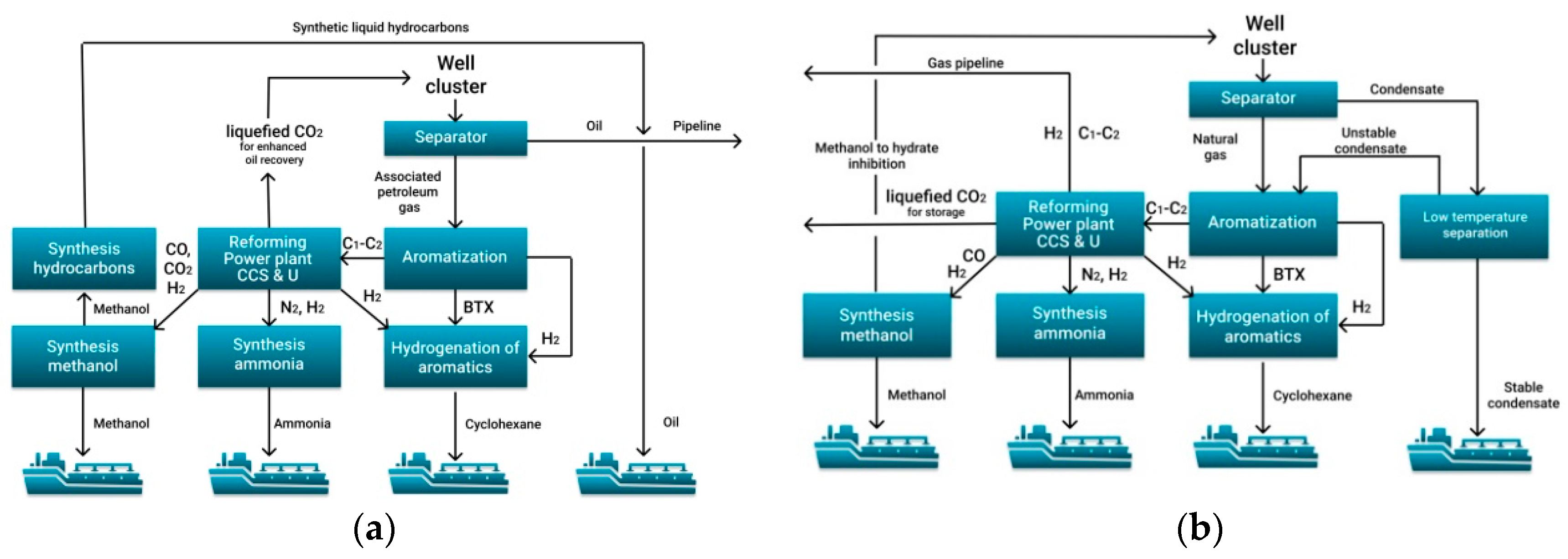
  • The most important are aromatization of C3+ hydrocarbon gases and unstable gas condensate to obtain benzene-toluene-xylene, as well as hydrogenation of benzene-toluene-xylene to produce cyclohexane.
  • The conversion of C1–C2 hydrocarbons for the further production of hydrogen, ammonia and methanol must combine processes with the addition of methane, water steam, oxygen and even carbon dioxide.
  • All production chains must be harmoniously linked into one production process, achieving a synergistic effect. This effect can be achieved for the combined hydrogen-methanol-ammonia production.
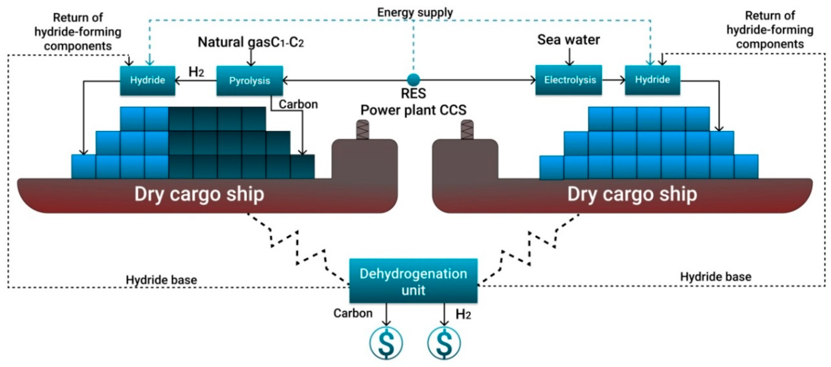
  • Due to the lack of fleet for shipping of compressed or liquefied hydrogen, it is suggested to use tankers and dry cargo vessels for the transport of bound hydrogen in liquid and solid form. For the existing gas transportation systems and port infrastructure, it is proposed to use C1–C2 pyrolysis to obtain turquoise hydrogen and solid carbon from renewable energy sources and to ship the compressed carbon and hydrogen bound into hydride.
Some of the processes described above are well known. However, they are practically not used in oil and gas fields, despite the fact that the development of gas chemical plants directly at the place of hydrocarbon production will reduce the cost of production. Such an oil and gas facility may be more efficient and more environmentally friendly than existing ones since it will have high-tech equipment and systems for the utilization of industrial wastewater and gases into absorption wells.
This article introduces conceptual Gas-To-Chem solutions for oil, gas and gas condensate fields taking into account the current trends to reduce carbon footprint of energy and chemical raw materials, as well as efforts towards the creation of low-carbon economics based on hydrogen. A low-carbon economy creates several opportunities for the use of products originating in the discussed regions: in the energy sector (hydrogen and ammonia burnt without CO2 emissions), chemical industry (cyclohexane and methanol binding carbon in chemical compounds), production of food and biomass (nitrogen from ammonia as the basis for fertilizers). The concept is based on modern gas chemical technologies with an emphasis on the production of substances with high added value and low carbon footprint. Ammonia, methanol and cyclohexane are considered as sources of a clean energy resource of hydrogen. In the article, the methods to increase production efficiency due to the complementary nature of each other gas chemical process and to ensure selling flexibility through diversification of production are presented. Such diversification will reduce investment risks and maintain profitability amid the transformation of international markets.
The concepts presented in the article could be the starting point for the transformation of the oil and gas sector in Arctic regions, considering the actual global environmental and climate agenda.

Author Contributions

Conceptualization, M.D. and G.B.; methodology, A.K. (Andrzej Kraslawski); validation, M.D.; formal analysis, A.K. (Andrzej Kraslawski); investigation, A.K. (Andrey Kunshin), D.S. and M.B.; resources, M.D.; data curation, G.B.; writing—original draft preparation, A.K. (Andrey Kunshin); writing—review and editing, G.B.; visualization, D.S.; supervision, M.D.; project administration, G.B. All authors have read and agreed to the published version of the manuscript.

Funding

This research received no external funding.

Institutional Review Board Statement

Not applicable.

Informed Consent Statement

Not applicable.

Data Availability Statement

The data presented in this study are available on request from the corresponding author. The data are not publicly available due to Federal Law of the Russian Federation “On Export Control”.

Conflicts of Interest

The authors declare no conflict of interest.

References

  1. Alekseeva, M.B.; Bogachev, V.F.; Gorenburgov, M.A. Systemic Diagnostics of the Arctic Industry Development Strategy. J. Min. Inst. 2019, 238, 450–458. [Google Scholar] [CrossRef] [Green Version]
  2. Vasiltsov, V.S.; Vasiltsova, V.M. Strategic Planning of Arctic Shelf Development Using Fractal Theory Tools. J. Min. Inst. 2018, 234, 663–672. [Google Scholar] [CrossRef]
  3. Evangelopoulou, S.; De Vita, A.; Zazias, G.; Capros, P. Energy System Modelling of Carbon-Neutral Hydrogen as an Enabler of Sectoral Integration within a Decarbonization Pathway. Energies 2019, 12, 2551. [Google Scholar] [CrossRef] [Green Version]
  4. A Hydrogen Strategy for a Climate Neutral Europe. Available online: https://ec.europa.eu/commission/presscorner/detail/en/FS_20_1296 (accessed on 20 July 2020).
  5. Energy Strategy of the Russian Federation for the Period up to 2035. Available online: https://minenergo.gov.ru/node/1026 (accessed on 10 November 2020).
  6. Eckpunktepapier der Ostdeutschen Kohleländer zur Entwicklung Einer Regionalen Wasserstoffwirtschaft. Available online: https://www.medienservice.sachsen.de/medien/medienobjekte/130485/download (accessed on 13 November 2020).
  7. Ilinova, A.A.; Romasheva, N.V.; Stroykov, G.A. Prospects and social effects of carbon dioxide sequestration and utilization projects. J. Min. Inst. 2020, 244, 493–502. [Google Scholar] [CrossRef]
  8. Tcvetkov, P.S.; Cherepovitsyn, A.E.; Fedoseev, S.V. The Changing Role of CO2 in the Transition to a Circular Economy: Review of Carbon Sequestration Projects. Sustainability 2019, 11, 5834. [Google Scholar] [CrossRef] [Green Version]
  9. Melaina, M.W.; Antonia, O.; Penev, M. Blending Hydrogen into Natural Gas Pipeline. Networks: A Review of Key Issues. 2013. Available online: https://www.nrel.gov/docs/fy13osti/51995.pdf (accessed on 5 October 2020).
  10. Litvinenko, V. The Role of Hydrocarbons in the Global Energy Agenda: The Focus on Liquefied Natural Gas. Resources 2020, 9, 59. [Google Scholar] [CrossRef]
  11. Saphin, A.K. Production of Hydrogen Plant Sand Construction of Hydrogen Infrastructure in Industrialized Countries. Technical and Investment Indicators of Installation Sand Hydrogen Stations; Issue 2; LLC Prima-Khimmash: St. Petersburg, Russia, 2015; p. 226. [Google Scholar]
  12. Salikhov, K.M.; Stoyanov, N.D.; Stoyanova, T.V. Using Optical Activation to Create Hydrogen and Hydrogen-Containing Gas Sensors. Key Eng. Mater. 2020, 854, 87–93. [Google Scholar] [CrossRef]
  13. Parkinson, B.; Tabatabaei, M.; Upham, D.C.; Ballinger, B.; Greig, C.; Smart, S.; McFarland, E. Hydrogen production using methane: Techno economics of decarbonizing fuels and chemicals. Int. J. Hydrogen Energy 2018, 43, 2540–2555. [Google Scholar] [CrossRef]
  14. Susmozas, A.; Iribarren, D.; Dufour, J. Assessing the Life-Cycle Performance of Hydrogen Production via Biofuel Reforming in Europe. Resources 2015, 4, 398–411. [Google Scholar] [CrossRef] [Green Version]
  15. Dahl, P.Y.; Christensen, T.S.; Winter-Madsen, S. Autothermal Reforming Technology for modern large-capacity methanol plants. In Proceedings of the International Conference Nitrogen and Syngas, Paris, France, 24–27 February 2014; p. 14. [Google Scholar]
  16. Dawood, F.; Anda, M.; Shafiullah, G.M. Hydrogen production for energy: An overview. Int. J. Hydrog. Energy 2019, 7, 107–154. [Google Scholar] [CrossRef]
  17. Liu, K.; Song, C.; Subraman, V. Hydrogen and Syngas Production and Purification Technologies; John Wiley & Sons: Hoboken, NJ, USA, 2010; p. 564. [Google Scholar] [CrossRef]
  18. Machlin, V.A.; Cetaruk, J.R. Modern technologies of producing synthesis gas from natural and associated gas. Sci. Tech. J. Chem. Ind. Today 2010, 3, 6–17. [Google Scholar]
  19. Indarto, A.; Palguandi, J. Syngas Production, Application and Environmental Impact; Nova Science Publishers: New York, NY, USA, 2013; p. 365. [Google Scholar]
  20. Zagashvili, U.V.; Levain, A.A.; Kuzmin, A.M.; Aniskevich, Y.V.; Vasilieva, O.V. Technology of hydrogen production using small transportable units based on high-temperature syngas generators. Sci. Tech. J. Vopr. Mater. Edeniya 2017, 2, 92–109. [Google Scholar]
  21. Zagashvili, U.V.; Levain, A.A.; Kuzmin, A.M. Principles of design of three-component gas synthesis gas. Oil and gas. LLC Obrakademnauka 2017, 4, 9–16. [Google Scholar]
  22. Buslaev, G.V. Technology of associated petroleum gas processing at remote Arctic oil and gas facilities to produce synthetic liquid hydrocarbons. In Proceedings of the Plenary Report at the XIX International Youth Scientific Conference SeverGeoEcoTech-2018, Ukhta, Russia, 21–23 March 2018. [Google Scholar]
  23. Abalaev, A.V.; Del Toro Fonseca, D.A.; Lewiner, I.I.; Vyatkin, Y.L. Optimization of the operating mode of shelf reactors with a fixed layer in the process of aromatization of hydrocarbons C5. Scientific service on the Internet: Search for new solutions. In Proceedings of the International Supercomputing Conference, Hamburg, Germany, 17–21 June 2012; pp. 273–277. [Google Scholar]
  24. Azhazha, V.M.; Tikhonovskiy, M.A.; Shepelev, A.G.; Kurilo, Y.P.; Ponomarenko, T.A.; Vinogradov, D.V. Materials for Hydrogen Storage: Analysis of Development Trends Based on Data on Information Flows. Questions of Nuclear Science and Technology. Series: Vacuum, Pure Materials, Superconductors; National Scientific Center, Kharkiv Institute of Physics and Technology: Kharkov, Ukraine, 2006; pp. 145–153. Available online: https://vant.kipt.kharkov.ua/ARTICLE/VANT_2006_1/article_2006_1_145.pdf (accessed on 10 July 2020).
  25. Baraban, A.P.; Gabis, I.E.; Dmitriev, V.A.; Dobrotvorskii, M.A.; Kuznetsov, V.G.; Matveeva, O.P.; Titov, S.A.; Voyt, A.P.; Yelets, D.I. Luminescent properties of aluminum hydride. J. Lumin. 2015, 166, 162–166. [Google Scholar] [CrossRef]
  26. Bazhin, V.Y.; Trushnikov, V.E.; Suslov, A.P. Simulation of partial oxidation of natural gas in a resource-saving reactor mixer. IOP Conf. Ser. Mater. Sci. Eng. 2020, 862, 862. [Google Scholar] [CrossRef]
  27. Belousova, O.Y.; Kutepov, B.I. Textbook of Aromatization of Hydrocarbons on Pentasyl-Containing Catalysts; Khimiya: Moscow, Russia, 2000; p. 95. [Google Scholar]
  28. Bilera, I.V. Education of Fine Soot When Receiving the Synthesis Gas under Conditions of Combustion of Methane. In The Gas Chemistry; Billera, I.V., Borisov, A.A., Borunova, A.B., Kolbanoskiy, Y.A., Korolev, Y.M., Rossokhin, I.V., Troshin, I.V., Eds.; Metaprocess Ltd.: Saint-Brice-Courcelles, France, 2010; Volume 3, pp. 72–78. [Google Scholar]
  29. Cooper, H.; Donnis, B.B.L. Aromatic saturation of distillates: An overview. Appl. Catal. A Gen. 1996, 137, 203–223. [Google Scholar] [CrossRef]
  30. Abanades, A.; Ruiz, E.; Ferruelo, E.M.; Hernández, F.; Cabanillas, A.; Martínez-Val, J.M.; Rubio, J.A.; López, C.; Gavela, R.; Barrera, G.; et al. Experimental analysis of direct thermal methane cracking. Int. J. Hydrog. Energy 2011, 36, 12877–12886. [Google Scholar] [CrossRef] [Green Version]
  31. Abbas, H.F.; Wan Daud, W.M.A. Hydrogen production by methane decomposition: A review. Int. J. Hydrog. Energy 2010, 35, 1160–1190. [Google Scholar] [CrossRef]
  32. Amin, A.M.; Croiset, E.; Epling, W. Review of methane catalytic cracking for hydrogen production. Int. J. Hydrogen Energy 2011, 36, 2904–2935. [Google Scholar] [CrossRef]
  33. Bode, A.; Anderlohr, C.; Bernnat, J.; Flick, F.; Glenk, F.; Klingler, D.; Kolios, G.; Scheiff, F.; Wechsung, A.; Hensmann, M.; et al. Feste und Fluide Produkte ausGas—FfPaG, Schlussbericht; BMBF: Bonn, Germany, 2018. [Google Scholar]
  34. Geißler, T.; Plevan, M.; Abánades, A.; Heinzel, A.; Mehravaran, K.; Rathnam, R.; Rubbia, C.; Salmieri, D.; Stoppel, L.; Stuckrad, S.; et al. Experimental investigation and thermo-chemical modeling of methane pyrolysis in a liquid metal bubble column reactor with a packed bed. Int. J. Hydrog. Energy 2015, 40, 14134–14146. [Google Scholar] [CrossRef]
  35. Moliner, R.; Suelves, I.; Lazaro, M.; Moreno, O. Thermocatalytic decomposition of methane over activated carbons: Influence of textural properties and surface chemistry. Int. J. Hydrog. Energy 2005, 30, 293–300. [Google Scholar] [CrossRef]
  36. Muradov, N.; Chen, Z.; Smith, F. Fossil hydrogen with reduced CO2 emission: Modeling thermocatalytic decomposition of methane in a fluidized bed of carbon particles. Int. J. Hydrog. Energy 2005, 30, 1149–1158. [Google Scholar] [CrossRef]
  37. Muradov, N.; Smith, F.; Huang, C.; T-Raissi, A. Autothermal catalytic pyrolysis of methane as a new route to hydrogen production with reduced CO2 emissions. Catal. Today 2006, 116, 281–288. [Google Scholar] [CrossRef]
  38. Plevan, M.; Geißler, T.; Abanades, A.; Mehravaran, K.; Rathnam, R.; Rubbia, C.; Salmieri, D.; Stoppel, L.; Stückrad, S.; Wetzel, T. Thermal cracking of methane in a liquid metal bubble column reactor: Experiments and kinetic analysis. Int. J. Hydrog. Energy 2015, 40, 8020–8033. [Google Scholar] [CrossRef]
  39. Schultz, I.; Agar, D.W. Decarbonization of fossil energy via methane pyrolysis using two reactor concepts: Fluid wall flow reactor and molten metal capillary reactor. Int. J. Hydrog. Energy 2015, 40, 11422–11427. [Google Scholar] [CrossRef]
  40. Osman, A.I.; Farrell, C.; Al-Muhtaseb, A.H.; Harrison, J.; Rooney, D.W. The production and application of carbon nanomaterials from high alkali silicate herbaceous biomass. Sci. Rep. 2020, 10, 1–13. [Google Scholar] [CrossRef]
  41. Ostadi, M.; Paso, K.G.; Rodriguez-Fabia, S.; Oi, L.E.; Manenti, F.; Hillestad, M. Process Integration of Green Hydrogen: Decarbonization of Chemical Industries. Energies 2020, 13, 4859. [Google Scholar] [CrossRef]
  42. Olivier, P.; Bourasseau, C.; Bouamama, P. Low-temperature electrolysis system modelling: A review. Renew. Sustain. Energy Rev. 2017, 78, 280–300. [Google Scholar] [CrossRef]
  43. Yu, L.; Zhu, Q.; Song, S.; McElhenny, B.; Wang, D.; Wu, C.; Qin, Z.; Bao, J.; Yu, Y.; Chen, S.; et al. Non-noble metal-nitride based electrocatalysts for high-performance alkaline seawater electrolysis. Nat. Commun. 2019, 10, 1–10. [Google Scholar] [CrossRef] [Green Version]
  44. Zhu, C.; Liu, C.; Fu, Y.; Gao, J.; Huang, H.; Liu, Y.; Kang, Z. Construction of CDs/CdS photocatalysts for stable and efficient hydrogen production in water and seawater. Appl. Catal. B Environ. 2019, 242, 178–185. [Google Scholar] [CrossRef]
  45. Hung, W.-H.; Xue, B.-Y.; Lin, T.-M.; Lu, S.-Y.; Tsao, I.-Y. A highly active selenized nickel-iron electrode with layered double hydroxide for electrocatalytic water splitting in saline electrolyte. Mater. Today Energy 2021, 19, 100575. [Google Scholar] [CrossRef]
  46. Jamesh, M.I.; Harb, M. Recent advances on hydrogen production through seawater electrolysis. Mater. Sci. Energy Technol. 2020, 3, 780–807. [Google Scholar] [CrossRef]
  47. Materials of SKOLKOVO Energy Centre, Moscow School of Management SKOLKOVO. Available online: https://energy.skolkovo.ru/downloads/documents/SEneC/Research/SKOLKOVO_EneC_Hydrogen-ecomy_Eng.pdf (accessed on 20 June 2019).
  48. Buyanov, S. Prospects for the construction of ships for Russian shipowners. In Proceedings of the Current State and Prospects for Development of Russian Bunker Services Market, Saint Petersburg, Russia, 27–28 June 2019; Available online: http://cniimf.ru/press-tsentr/news/870/ (accessed on 2 July 2019).
  49. Litvinenko, V.S.; Tsvetkov, P.S.; Dvoynikov, M.V.; Buslaev, G.V. Barriers to implementation of hydrogen initiatives in the context of global energy sustainable development. J. Min. Inst. 2020, 244, 421–431. [Google Scholar] [CrossRef]
  50. Anhydrous Liquefied Ammonia. Specifications; Russian Government Standard GOST 6221-90; Standartinform: Moscow, Russia, 2011; Available online: http://www.gostrf.com/normadata/1/4294823/4294823189.pdf (accessed on 15 September 2020).
  51. Production of Ammonia, Mineral Fertilizers and Inorganic Acids. Information and Technical Directory (ITD) 2019. Available online: http://docs.cntd.ru/document/564068887 (accessed on 13 November 2020).
  52. Samuel, S.A.; Vincenzo, L.; Xiaoti, C.; Na, L.; Jimin, Z.; Simon, L.S.; Søren, H.J.; Mads, P.N.; Søren, K.K. A Review of The Methanol Economy: The Fuel Cell Route. Energies 2020, 13, 1–32. [Google Scholar]
  53. Yurieva, T.M.; Plyasova, L.; Makarova, O.; Krieger, T. Mechanisms for hydrogenation of acetone to isopropanol and of carbon oxides to methanol over copper-containing oxide catalysts. J. Mol. Catal. A Chem. 1996, 113, 455–468. [Google Scholar] [CrossRef]
  54. Chen, W.H.; Chen, C.Y. Water gas shift reaction for hydrogen production and carbon dioxide capture: A review. Appl. Energy 2020, 258, 114078. [Google Scholar] [CrossRef]
  55. Angell, V.W.; Graham, H.J.; Post, G.J. Case History: Ice Island Drilling Application and Well Considerations in Alaskan Beaufort Sea. Soc. Pet. Eng. 1990. [Google Scholar] [CrossRef]
  56. Bolotov, V.A.; Cheremisina, O.V.; Ponomareva, M.A.; Alferova, D.A. Prospects for the use of the sorbent for purification of gases from sulfur-containing components on the basis of manganese ore. Key Eng. Mater. 2020, 836, 13–18. [Google Scholar] [CrossRef]
  57. Vyatkin, Y.L.; Lishchiner, I.I.; Sinitsyn, S.A.; Kuz’min, A.M. Perspective directions of chemical processing of hydrocarbon raw materials. Neftegaz 2020, 4, 114–118. [Google Scholar]
  58. Rusman, N.A.A.; Dahari, M.A. Review on the current progress of metal hydrides material for solid-state hydrogen storage applications. Int. J. Hydrog. Energy 2016, 12108–12126. [Google Scholar] [CrossRef]
  59. Tarasov, B.P. Problems and prospects of creating materials for hydrogen storage in a bound state. Int. Sci. J. Altern. Energy Ecol. 2006, 2, 11–17. [Google Scholar]
  60. Tarasov, B.P.; Burnasheva, V.V.; Lototsky, M.V.; Yartys, V.A. Methods of hydrogen storage and the possibility of using metallohydrides. Int. Sci. J. Altern. Energy Ecol. 2005, 12, 14–37. [Google Scholar]
  61. Tarasov, B.P.; Lototsky, M.V.; Yartys, V.A. The Problem of hydrogen storage and prospects for using hydrides for hydrogen storage. Russ. Chem. J. 2006, 6, 34–48. [Google Scholar]
  62. McKay, M. Hydrogen Compounds of Metals; Mir: Moscow, Russia, 1968; p. 244. [Google Scholar]
  63. York, A.P.E.; Xiao, T.; Green, M.L.H. Brief overview of the partial oxidation of methane to synthesis gas. Top. Catal. 2003, 22, 345–358. [Google Scholar] [CrossRef]
  64. Schlapbach, L. Hydrogen as a fuel and its storage for mobility and transport. MRS Bull. 2002, 675–679. [Google Scholar] [CrossRef] [Green Version]
  65. Kalashnikov, J.A. Physical Chemistry of Substances at High Pressures; Higher School: Moscow, Russia, 1987; p. 237. [Google Scholar]
  66. Hydride Hydrogen Storage System. Available online: https://lektsia.com/2x8693.html (accessed on 13 November 2020).
  67. Landrum, L.; Holland, M.M. Extremes become routine in an emerging new Arctic. Nat. Clim. Chang. 2020, 10, 1108–1115. [Google Scholar] [CrossRef]
  68. Fateev, V.N.; Alekseeva, O.K.; Korobtsev, S.V.; Seregina, E.A.; Fateeva, T.V.; Grigoriev, A.S.; Aliev, A.S. Problems of hydrogen accumulation and hydrogen storage. KimyaProblemleri Baku Aliyev Akif Shihanoglu 2018, 4, 453–483. [Google Scholar] [CrossRef]
  69. Liu, C.; Li, F.; Ma, L.-P.; Cheng, H.-M. Advanced materials for energy storage. Adv. Mater. 2010, 22, E28–E62. [Google Scholar] [CrossRef]
  70. Kornev, A.V.; Barkan, M.S. Prospects for the use of associated gas of oil development as energy product. Int. J. Energy Econ. Policy 2017, 7, 374–383. [Google Scholar]
  71. Kozʼmenko, S.Y.; Masloboev, V.A.; Matviishin, D.A. Justification of Economic Benefits of Arctic LNG Transportation by Sea. J. Min. Inst. 2018, 233, 554–560. [Google Scholar] [CrossRef]
  72. Buslaev, G.; Morenov, V.; Konyaev, Y.; Kraslawski, A. Reduction of carbon footprint of the production and field transport of high-viscosity oils in the Arctic region. Chem. Eng. Process. Process Intensif. 2020, 108189. [Google Scholar] [CrossRef]
  73. Morenov, V.A.; Leusheva, E.L.; Buslaev, G.V.; Gudmestad, O.T. System of comprehensive energy-efficient utilization of associated petroleum gas with reduced carbon footprint in the field conditions. Energies 2020, 13, 4921. [Google Scholar] [CrossRef]
  74. Bode, A.; Agar, D.W.; Buker, K.; Göke, V.; Hensmann, M.; Janhsen, U.; Klingler, D.; Schlichting, J.; Schunk, S.A. Research cooperation develops innovative technology for environmentally sustainable syngas production from carbon dioxide and hydrogen. In Proceedings of the 20th World Hydrogen Energy Conference, Gwangju, Korea, 15–20 June 2014. [Google Scholar]
  75. Church, J.A.; Clark, P.U.; Cazenave, A.; Gregory, J.M.; Jevrejeva, S.; Levermann, A.; Merrifield, M.A.; Milne, G.A.; Nerem, R.S.; Nunn, P.D.; et al. Sea Level Change. Contribution of Working Group I to the Fifth Assessment Report of the Intergovernmental Panel on Climate Change. In Climate Change 2013: The Physical Science Basis; Stocker, T.F.D., Qin, G.-K., Plattner, M., Tignor, S.K., Allen, J., Boschung, A., Nauels, Y., Xia, V.B., Midgley, P.M., Eds.; Cambridge University Press: Cambridge, UK; New York, NY, USA, 2013. [Google Scholar]
  76. Accelerating the Uptake of CCS: Industrial Use of Captured Carbon Dioxide; Global CCS Institute: Melbourne, Australia, 2011.
  77. Kirsanova, N.Y.; Lenkovets, O.M.; Nikulina, A.Y. The Role and Future Outlook for Renewable Energy in the Arctic Zone of Russian Federation. Eur. Res. Stud. J. 2018, 21, 356–368. [Google Scholar]
  78. Wang, M.; Li, J.; Chen, L.; Lu, Y. Miniature NH3 cracker based on microfibrous entrapped Ni-CeO2/Al2O3 catalyst monolith for portable fuel cell power supplies. Int. J. Hydrog. Energy 2009, 34, 1710–1716. [Google Scholar] [CrossRef]
  79. Mukhovikova, N.K.; Nepomnyakschikh, Y.V. Preparation of Formaldehyde by Oxidative Dehydration of Methanol. In Proceedings of the XI All-Russian Scientific-Practical Conference of Young Scientists «YOUNG RUSSIA», Moscow, Russia, 2–4 October 2019; Available online: http://science.kuzstu.ru/wp-content/Events/Conference/RM/2019/RM19/pages/Articles/70207.pdf (accessed on 22 October 2020).
Figure 1. Product transportation routes of the Arctic zone of the Russian Federation to the countries of the European Union and the Asia-Pacific region.
Resources 10 00003 g001
Figure 2. Concept for the development of a remote Arctic oil and gas field (a), gas condensate (b) with the possibility of producing and transporting blue hydrogen bound to methanol, ammonia and cyclohexane.
Resources 10 00003 g002
Figure 3. Steam methane reforming unit with water gas reforming reactors and amine purification. R-1—conversion reactor; R-2-3—equilibrium reactor for additional oxidation of CO and CO2; M-1—mixer; H-1-5—heat exchanger; C-1-2—refrigerator-condenser; S-1—separator for separating liquid products; A-1—absorber; SP—adsorber.
Resources 10 00003 g003
Figure 4. Preparation of synthesis gas with its subsequent processing into methanol. R-1—methanol synthesis reactor; M-1—mixer; H-1—heat exchanger; C-1—refrigerator-condenser; S—separator for separating liquid products; D—flow divider; CC—centrifugal compressor.
Resources 10 00003 g004
Figure 5. Scheme of ammonia production from a nitrogen-hydrogen mixture. R-1—ammonia synthesis column; R-2-3—condensation column; M-1-3—mixer; H-1—remote heat exchanger; C-1-2—refrigerator-condenser; S-1-2—separator for separating liquid products; D-1-2 filter—flow divider; CC-1—turbocharger; V-1-3—valves.
Resources 10 00003 g005
Figure 6. Concept of arranging a remote Arctic gas field with the possibility of producing and transporting solid carbon and turquoise hydrogen as a hydride using a dry cargo ship.
Resources 10 00003 g006
Publisher’s Note: MDPI stays neutral with regard to jurisdictional claims in published maps and institutional affiliations.

