Abstract
Video segmentation based on the Mixture of Gaussian (MoG) algorithm is widely used in video processing systems, and hardware implementations have been proposed in the past years. Most previous work focused on high-performance custom design of the MoG algorithm to meet real-time requirement of high-frame-rate high-resolution video segmentation tasks. This paper focuses on the System-on-Chip (SoC) design and the priority is SoC integration of the system for flexibility/adaptability, while at the same time, custom design of the original MoG algorithm is included. To maximally retain the accuracy of the MoG algorithm for best segmentation performance, we minimally modified the MoG algorithm for hardware implementation at the cost of hardware resources. The MoG algorithm is custom-implemented as a hardware IP (Intellectual Property), which is then integrated within an SoC platform together with other video processing components, so that some key control parameters can be configured on-line, which makes the video segmentation system most suitable for different scenarios. The proposed implementation has been demonstrated and tested on a Xilinx Spartan-3A DSP Video Starter Board. Experiment results show that under a clock frequency of 25 MHz, this design meets the real-time requirement for VGA resolution (640 × 480) at 30 fps (frame-per-second).
1. Introduction and Previous Work
Video segmentation is typically an indispensable part in industrial applications such as video surveillance, object detection, recognition and tracking. Conventional video segmentation techniques include non-adaptive methods such as static background subtraction and adaptive methods such as frame difference (FD) [1,2,3]. The non-adaptive methods have almost been abandoned because of the need for manual initialization and/or re-initialization and they are not suitable for highly automated surveillance environments or applications. Adaptive methods that can dynamically adjust to the environment changes are favored for improved accuracy. Besides FD, there are several other adaptive video segmentation methods, such as median filter (MF), linear predictive filter (LPF), Mixture-of-Gaussian (MoG), and kernel density estimation (KDE) [1,2,3]. More advanced algorithms have also been continuously proposed for better accuracy (or intelligence) [4,5,6].
Video segmentation is arguably one of the most computational intensive steps in a typical video processing system [7]. In our software implementation of video segmentation based on a 3-mixture MoG algorithm on an Intel i7-4790 processor, the performance was at most 2 frames per second with a VGA resolution of 640 × 480, which cannot meet the real-time requirement of at least 15 frames per second (fps) for most video processing applications. Therefore, in the past years, there has been significant effort to improve real-time operation by hardware acceleration of the video segmentation [8,9], which is also the main context of this work. However, which algorithm is selected for video segmentation may have a significant effect on its hardware implementation. The most sophisticated algorithm that provides optimal accuracy for video segmentation may not be a good candidate for hardware acceleration due to realistic constraints from hardware resources and/or tremendous complexity of hardware implementation. A qualitative comparison of several popular algorithms has been made in [7] in terms of performance, memory requirement, segmentation quality, and hardware complexity and we cited their results in Table 1. It can be seen that MoG may have the best trade-off among these adaptive video segmentation algorithms.

Table 1.
Comparison of different adaptive video segmentation algorithms [7].
In the past years, some work has been reported on hardware implementation/acceleration of MoG algorithm for video segmentation [7,8,9,10,11,12,13,14]. Early work on hardware implementation of MoG algorithm was conducted in [8,9]. Later, the work was improved in [7], in which the MoG algorithm was customarily designed, implemented and verified using a Xilinx VirtexII pro Vp30 FPGA platform. In custom hardware implementation, one main innovation is that the authors used a variety of memory access reduction schemes to achieve almost 70% memory bandwidth reduction compared to the worst-case scenario. The design in [7] can meet the real-time requirement of most high-frame-rate high-resolution segmentation applications (such as VGA resolution of 640 × 480 at 25 fps in real-time). [10,11] reported work to further improve the performance of MoG hardware implementation to be able to support full high-definition (1080 × 1920) video segmentation in real-time. [10] targets a reduction in the power consumption of an FPGA-based hardware implementation, which was claimed to consume 600 times less power compared to the traditional embedded software implementation. [11] presents a customized implementation of the MoG algorithm for full high-definition videos to reduce power consumption and hardware resources after simplifying/modifying the MoG algorithm. To further increase the performance of MoG hardware implementation, recent work in [12,13,14] explored to leverage the power of modern multi-core processors and graphic-processing-units (GPU) with parallel or vector processing techniques.
The MoG algorithm in [9,10,11] was implemented mainly from a custom design perspective so that it achieves relatively high performance with a relatively low hardware complexity and small amount of hardware resources. However, as a customized hardware implementation, the design in [9,10,11] lacks adaptability/flexibility. Some key control parameters in the MoG algorithm, such as learning rate and threshold, cannot be changed on the fly, which limits the adaptability of the design. If such a custom design of the MoG algorithm can be embedded as hardware IP in an SoC platform that allows easy integration into other video processing components, the overall SoC design would be more adaptable to different scenarios or environments. The SoC design has many advantages. First, a hardware IP can be integrated into an SoC architecture so long as it meets the specified bus standard. The designer can design other hardware IPs based on the specified bus standard and integrate them into the SoC architecture, and this gives flexibility that allows rapid prototype implementations of different applications, such as object detection [15] or object tracking [16]. Second, with the SoC design, configuration of algorithm-related control parameters would be much easier, which can be performed on-line via a micro-control unit in the SoC architecture. On-line re-configuration of these parameters would allow optimal video segmentation performance under various scenarios or environments. For example, when the video segmentation system was used in the vehicle detection application to be discussed in Section 4, the user may need to adjust major control parameters of the MoG algorithm such that optimal video segmentation results are achieved in the sense that maximum vehicle detection accuracy was observed.
Motivated by the above considerations, this paper focuses on the SoC design and the priority is SoC integration of the system for flexibility/adaptability, while at the same time including custom design of the original MoG algorithm. We custom-implemented the MoG algorithm as hardware IP, and integrated it within an SoC architecture for an MoG-based video segmentation system. We made minimal modifications to the original MoG algorithm for maximum accuracy at the expense of hardware resources. A micro-control unit in the SoC architecture is used to configure important control parameters of the MoG algorithm on-line. The SoC architecture has three types of bus interfaces to allow integration of the MoG IP and other functional blocks. The proposed SoC implementation of the video segmentation system has been tested on an SoC architecture from Xilinx Spartan-3A DSP Video Starter Board [17]. Under a clock frequency of only 25 MHz, the proposed SoC design meets the real-time requirement of VGA videos (with a resolution of 640 × 480) at 30 fps.
The rest of the paper is organized as follows. Section 2 briefly introduces the computation flow of the original MoG algorithm from a hardware implementation point of view. Section 3 presents the implementation of the MoG algorithm as hardware IP and integration of the MoG IP in an SoC architecture for implementation of the video segmentation system. Experimental results are presented in Section 4, and finally, conclusions are drawn in Section 5.
2. The Mixture-of-Gaussian Algorithm for Video Segmentation
The MoG algorithm for video segmentation was first proposed in [18]. This algorithm considers the values of a pixel at a particular position (x, y) of an image over time as a “pixel process”, and the recent history of the pixel is modeled by a mixture of Gaussian distributions. The probability of observing a value of is [18]:
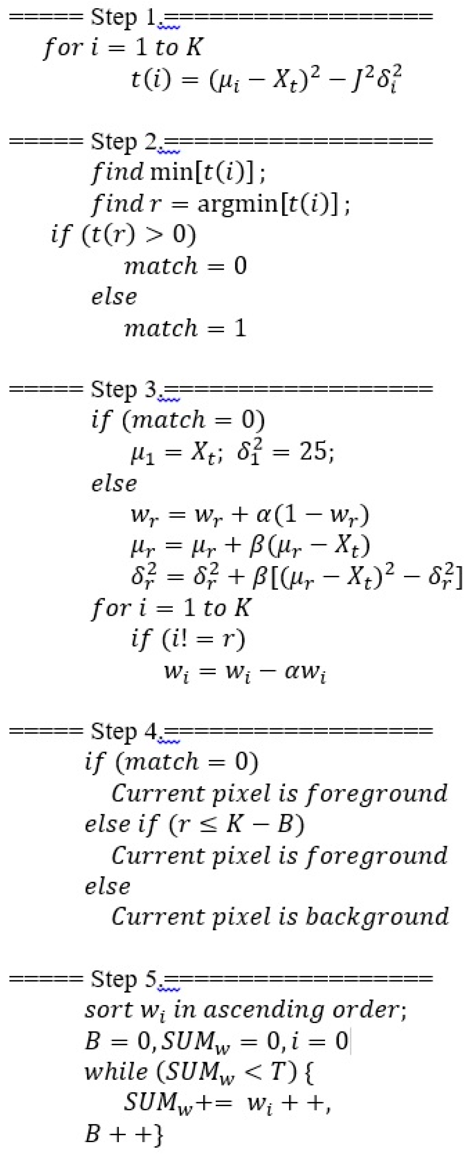
where is the incoming pixel at time (or frame ), the number of Gaussian distributions, the weighting factor, a Gaussian probability density function, the mean value and the covariance matrix of the Gaussian distribution at time ( where denotes the variance of the Gaussian distribution at time and the identity matrix). In the following, we describe the computation flow of the MoG algorithm in Figure 1 from a hardware implementation point of view.
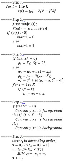
Figure 1.
Computation flow the MoG algorithm.
A match is defined as the incoming pixel within (for instance, 2.5) times the standard deviation of the mean. The operations outlined in Step1 (in Figure 1) can be used to compute the matching measure (denoted by in Step1) of with respect to each Gaussian distribution from 1 to .
From the computed matching measures, the minimum measure (denoted by ) is found together with its index (note that the Gaussian distributions are sorted ascendingly in terms of weights at any time). If the minimum measure is larger than 0, then it means that the incoming pixel has no match against any of the Gaussian distributions. Otherwise, has a match. These operations are outlined in Step 2 below.
Continuing in Step 3, if no match is identified in the previous step, the Gaussian distribution with the lowest weight (which will be always the first distribution as they are sorted ascendingly in weights ) will have its mean replaced by and variance initialized with a typical value (for instance, 25) [18]. On the other hand, if a match is found at time against the Gaussian distribution (that has minimum matching measure from Step 2), then , , and for the next frame at time are updated as follows [18]:
where , are the learning rates to update weight, mean and variance. Note that the weight for the matching distribution is increased. For the rest of the Gaussian distributions that do not match, they will have their weights decreased and mean/variance kept the same, as follows:
In Step 4, foreground or background is declared for video segmentation outputs. When no match is asserted from Step 2, then current observation is declared as foreground for the current pixel. In the case when a match is found, the current observation would be declared a foreground (or background) if the matching distribution, whose index is obtained from Step 2, represents foreground (or background). At any time the portion of the Gaussian distributions ( out of ) that accounts for the background is defined to be
where , the threshold, is a measure of the minimum portion of the data that is used to account for the background. Since the Gaussian distributions are sorted ascendingly in terms of weights , a simple way to determine whether the matching Gaussian distribution indexed by represents foreground or background is to compare against , as shown in Step 4 below.
Lastly in Step 5, the Gaussian distributions are sorted ascendingly again after weight update from the previous step, and finally the portion of them that account for the background (i.e., parameter ) is computed, so they are ready for the operations in the next image frame.
Note that to retain maximum accuracy from the original MoG algorithm, we did not simplify the algorithm for reduced hardware implementation complexity and hardware resources as done in [9]. Also, note that , , and should be easily adjustable for optimal video segmentation performance depending on the scenario, for instance, a fast or slow light change environment.
3. Hardware Implementation of the MoG IP and SoC Implementation of the Video Segmentation System
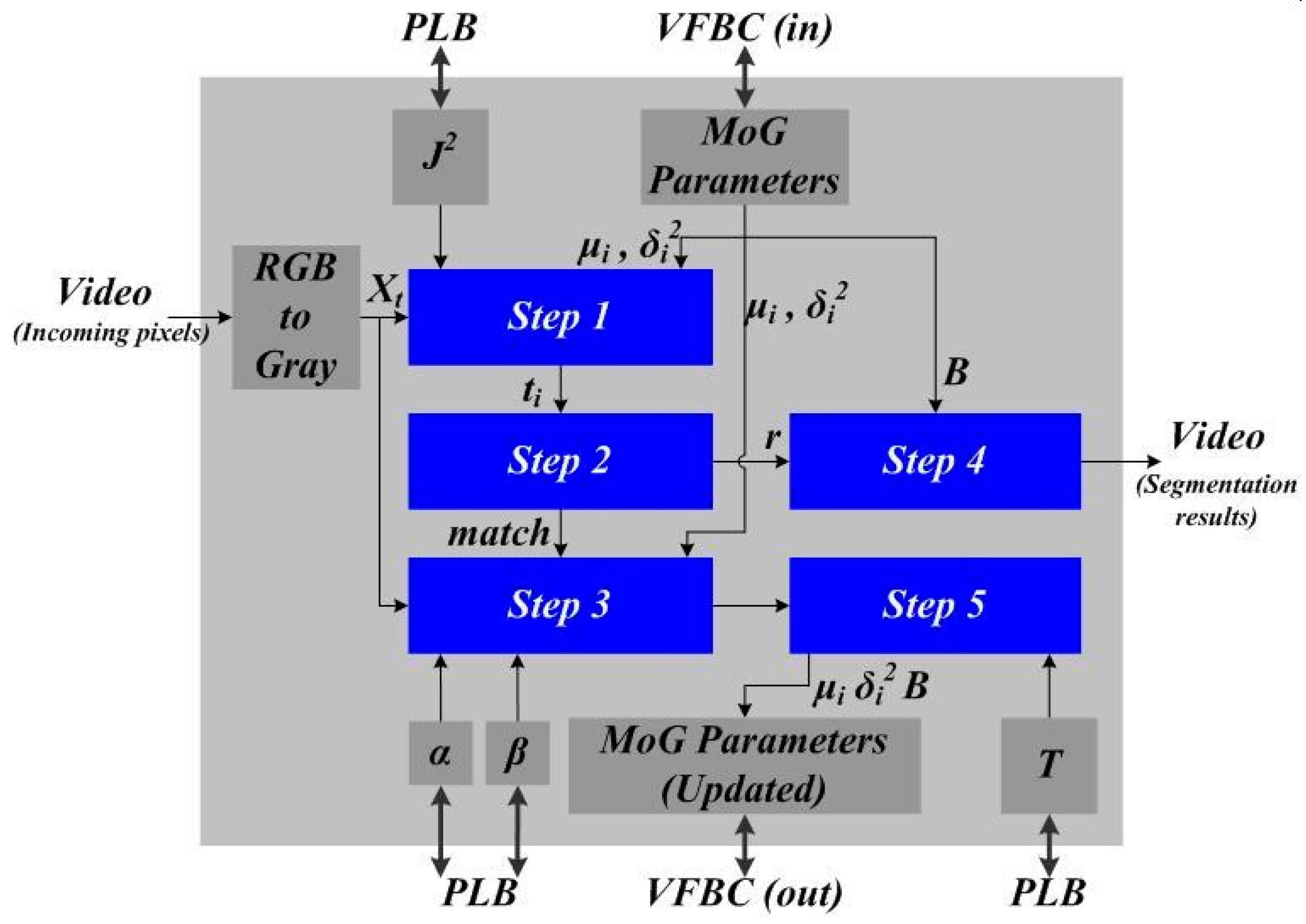
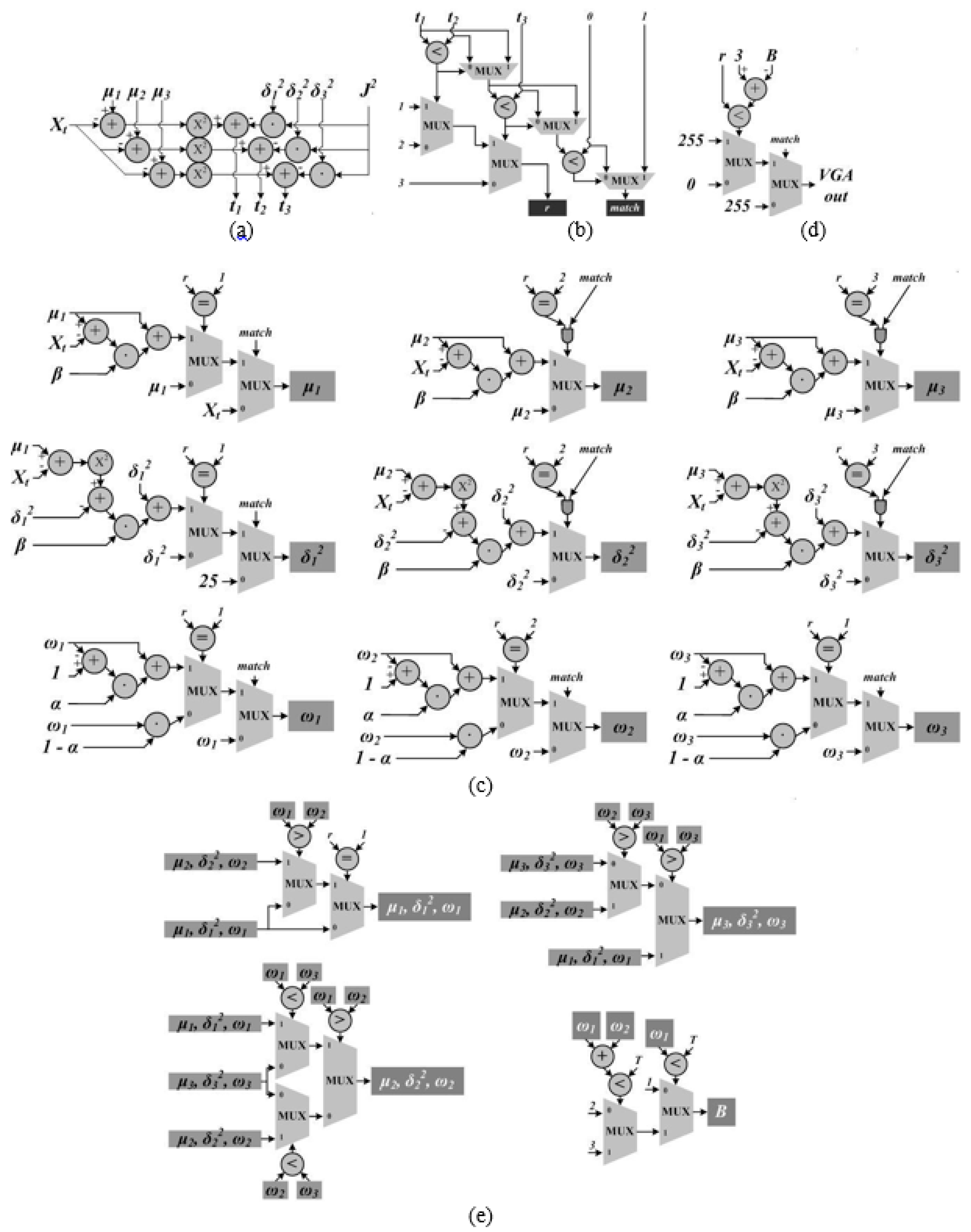
With the computation flow of the MoG algorithm laid out in the previous Section, its block-level diagram of the hardware implementation is shown in Figure 2. It was implemented in the Xilinx Spartan-3A DSP FPGA Video Starter Board [17]. The core design of the MoG algorithm mainly consists of the five functional blocks denoted in blue, which corresponds to the five processing steps of the computation flow described in the last Section. The detailed circuits to implement each processing step can be found from Figure 3 and we used a 21-stage pipeline design for these circuits.
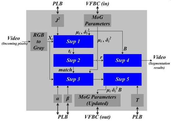
Figure 2.
Hardware implementation of the MoG algorithm.
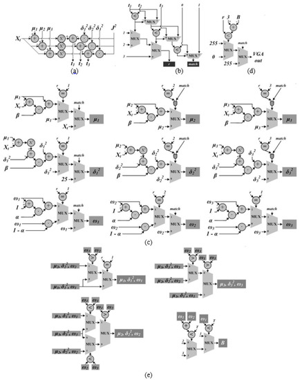
Figure 3.
Circuit implementations for Step 1 (a), Step 2 (b), Step 3 (c), Step 4 (d) and Step 5 (e).
After series transfer of the incoming pixels of the input video, each pixel was first converted from RGB to grayscale of 8-bits, denoted by in Figure 2. As the MoG IP was implemented in Xilinx Spartan-3A DSP Video Starter Board, it utilizes three types of signal interfaces. The first one is the video bus interface [18], which is used for incoming pixels and segmentation results of video output. The second interface is the processor local bus (denoted as PLB in Figure 2) interface [19], which connects the registers , , and to the micro-controller, i.e., the Xilinx MicroBlaze [20]. Each register is assigned 8 bits (integer for and fractional for , and ). The third signal interface is the video frame buffer controller (VFBC) bus interface [21], which connects the MoG IP to Xilinx multi-port memory controller (MPMC), and this is used to load the Gaussian distribution parameters (such as ) from and store them to the memory. The bit width of the VFBC bus is set to 64 [17]. The mean parameter needs a minimum of 16 bits to represent its value (8-bit integer and 8-bit fractional). The variance parameter also needs a minimum of 16 bits to represent its value (8-bit integer and 8-bit fractional). The weight parameter needs a minimum of 8 bits to represent its value (8-bit fractional). As a result, each Gaussian distribution requires (16 + 16 + 8) = 40 bits. Therefore, given the maximum 64 bits of the VFBC bus, the adopted hardware platform needs to use multiple clock cycles to load and store parameters of multiple Gaussian distributions. Another 4 bits (integer) of the VFBC bus can be used for the parameter B in equation (4) above. For a typical video of VGA resolution (640 × 480), to store all parameters of the 3-mixture Gaussian model (i.e., , we need 640 × 480 × 40 × 3 bits = 4.6 Mega Bytes of memory space.
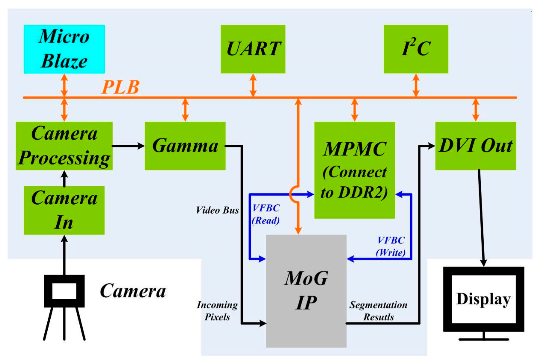
As we mentioned in Section 1, if the custom hardware implementation of the MoG algorithm can be embedded as hardware IP in a System-on-Chip (SoC) platform that allows easy integration to other video processing and control components, the overall SoC system is more flexible and adaptable. With this motivation, we integrated the custom-implemented MoG IP described above to other functional blocks (denoted in green and blue) within a SoC architecture as shown in Figure 4. In our example implementation, the adopted SoC architecture is from the Xilinx Spartan-3A DSP FPGA Video Starter board [17]. Except for the MoG IP, which is customarily designed, all other functional blocks are available from the board (UART stands for Universal Asynchronous Receiver/Transmitter and I2C for Inter-Integrated Circuit) [17].
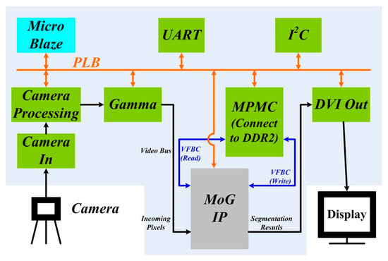
Figure 4.
SoC implementation of the video segmentation system with embedded MoG IP.
After embedding the MoG IP in the SoC architecture, the overall video segmentation system works under three clock domains. The components connected to PLB bus work under the 62.5 MHz clock. The components connected to Video Bus and VFBC work under the 25 MHz clock domain. The DDR2 SRAM (not shown in Figure 4) connected to the MPMC work under the 250 MHz clock domain. Some components connected to both PLB and Video Bus, such as Camera Processing and MoG IP, work under two clock domains. MPMC is the only component that works under all of the three clock domains.
One of the main advantages of the proposed SoC implementation of the video segmentation system is that the system is very adaptable as most of the components are connected to micro-controller (i.e., the MicroBlaze) via PLB and these components can communicate with each other via the micro-controller. For example, if it is desired to change or reset the learning rate of the MoG IP via UART, one can send commands to UART first, and then to the micro-controller via PLB. Once the micro-controller receives these commands, it will configure the value of register to the desired one via PLB. This process is independent from video processing, which means that the configuration can be performed on-line. In the MoG IP, the configurable parameters are , , and . Users can configure these parameters on-line to most ideal values experimentally depending the specific scenario for optimal video segmentation performance. On the other hand, since video segmentation based on MoG typically plays a pre-processing role in many larger applications such as video surveillance, object detection, and object tracking, an SoC platform is flexible to allow rapid prototyping of diverse applications. For example, if the designer targets object detection [15] or tracking [16], additional video processing modules such as filtering and tracking, could be designed and integrated within the SoC platform for rapid prototyping of the application.
4. Experiment Results and Applications
The proposed SoC implementation of the video segmentation system based on the MoG algorithm has been fully tested and verified using the Xilinx Spartan-3A DSP FPGA Video Starter Board [17]. The critical path delay of the MoG hardware IP is 7.77 ns. The overall design takes 14 k Slices, 12 k Slice Flip Flops, 15 k 4-Input LUTs, 77 BRAMs, 11 DSP48As, and 2 DCMs. The utilization of the FPGA hardware resources for the implementation is shown in Table 2, and Table 3 shows the hardware resources for each major functional block in the video segmentation system in Figure 4.

Table 2.
Summary of utilization of hardware resources.

Table 3.
Hardware resources of different blocks in the video segmentation system.
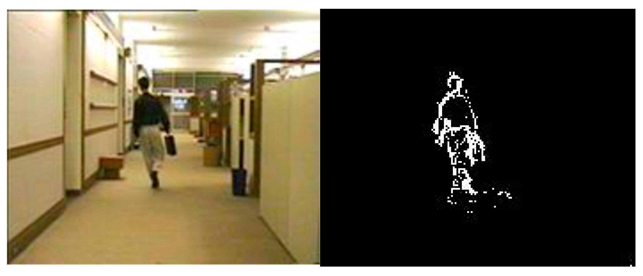
An sample output of field testing of the video segmentation system is shown in Figure 5 when targeting walking pedestrians in an indoor office environment ( = 2.5, and ). Figure 6 shows the segmentation results targeting moving vehicles at an outdoor intersection. These sample outputs (before morphological processing) have been compared to the ground truth from the pure software implementation of the video segmentation system based on the original MoG algorithm, and it was found the outputs were almost 100% accurate when counting the numbers of matched segmentation results among all pixels in the images. Experiments show that the proposed SoC implementation can support VGA resolution (640 × 480) at 30 fps in real-time under 25 MHz clock frequency. A performance summary of the video segmentation system in given in Table 4.
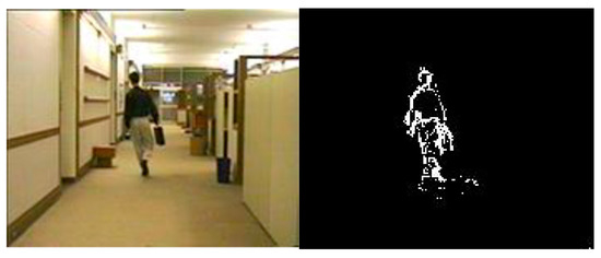
Figure 5.
Video Segmentation Results for an Indoor Pedestrian.

Figure 6.
Video Segmentation Results for Outdoor Moving Vehicles.

Table 4.
Performance summary of the implementation.
Such an SoC implementation of the video segmentation system can be used in rapid prototyping of many industrial applications. We show an example of applying the system for rapid prototyping of a vehicle detection application for vehicle merging assistance. A separate object detection module was designed to extract the segmented vehicles from the MoG IP, and integrated within the same SoC design. If vehicles at both merging lanes were detected, a warning signal is issued and wirelessly transmitted to a nearby traffic message board to turn on, for example, the flashing lights to alert the drivers on both lanes to prevent collision. The overall hardware prototype system is shown in Figure 7 and it has been successfully tested at the intersection of I35 highway and Route 53 in Duluth Minnesota where two ramp lanes merge into one [22]. In this specific application, optimal video segmentation results in terms of maximum vehicle detection accuracy was achieved by adjusting major control parameters of the MoG algorithm.

Figure 7.
Application of the proposed SoC implementation of video segmentation to object detection for vehicle merging assistance.
Finally, we made a comparison of the proposed SoC implementation of the video segmentation system with other relevant works reported [7,8,9,10,11]. The designs reported in [7,8,9,10,11] all had the custom design perspective, and the priority was to have a high-performance design with reasonable accuracy while reducing the amount of hardware resources and power consumption. With that perspective, the design in [7,8,9,10,11] first modified and simplified the MoG algorithm for reduced hardware implementation complexity and hardware resources at the cost of algorithm accuracy. For example, the design in [7] simplified Step 5 (see Section 2) by simply comparing the individual weights instead of summation of weights against a threshold value, which reduces segmentation accuracy when the background distribution does not dominate the Gaussian distributions (and this happens when foreground appearance is relatively frequent). In addition, the design in [7] simplified Step 3 when computing by skipping multiplication operations involving learning rates , and instead used incremental addition of 1/-1, which also significantly reduced memory bandwidth by neglecting the fraction portion of and . Compared to the design in [7,8,9,10,11], our proposed design has the SoC design perspective and the priority is SoC integration of the system for flexibility/adaptability, while at the same time includes custom design of the original MoG algorithm. From such a perspective, note that the proposed design is more flexible than those in [7,8,9,10,11] thanks to the SoC integration, which allows users to configure parameters on-line for optimal video segmentation performance depending on the specific scenario. On the other hand, additional video processing components such as filtering and morphological operations, object extraction, etc., can be developed and integrated within the same SoC platform, which makes it flexible to allow fast prototype implementations of different applications such as video surveillance, object recognition and object tracking. Also note that the proposed design retains the original MoG algorithm with minimal modification for best accuracy at the cost of more hardware resources and design complexity.
A comparison of the two designs in terms of hardware resources is given in Table 5, and it is seen that our design consumes more hardware resources than [7] due to limited algorithm simplification. On the other hand, there is a clear tradeoff between flexibility of the proposed SoC design and extra hardware resources compared to the previous work [7]. A comparison of their performances is shown in Table 5 as well. Basically, the two designs have almost the same performance in terms of processing speed. Finally, note that the proposed design (and also the design in [7]) can further improve its performance if modern, more advanced hardware platforms were used as in [10,11]. For example, in our design, increments of the bit-width of the VFBC bus and clock frequency would allow support of higher resolutions. As a reference, the recent design presented in [11] can support full HD (1920 × 1080) segmentation at 90 fps when implementing the MoG algorithm from the OpenCV library on a Virtex6 FPGA, which makes the design 18 times faster than our design.

Table 5.
A comparison of the Hardware Resources and Performance Measures.
5. Conclusions
This paper presents an SoC hardware implementation of real-time video segmentation system based on the MoG algorithm. Compared to previous designs from custom design perspective for high-performance (i.e., support of higher resolution, reduced hardware sources and power consumption), the proposed design is undertaken from the SoC integration perspective for flexibility/adaptability. We first custom-implemented hardware IP for the MoG algorithm and then integrated it to other video processing components in a SoC architecture. When designing the MoG IP, we targeted the original MoG algorithm without simplification at the cost of hardware resources and complexity. The SoC design not only makes the overall system more adaptable to different scenarios via on-line parameter control, but also flexible to allow easy integration of other hardware IPs for rapid prototyping of diverse applications. The proposed implementation has been demonstrated and tested on the Xilinx Spartan-3A DSP Video Starter Board. Experiment results show that under a clock frequency of 25 MHz, this design meets real-time video segmentation for VGA resolution (640 × 480) at 30 fps (frame-per-second). Such an SoC implementation of the video segmentation system can be used in rapid prototyping of many industrial applications. In future work, we look to improve the SoC design so that not only major control parameters of the MoG algorithm can be configured but also the algorithm design itself (such as number of Gaussian distributions, bit width, etc.) such that is can be more flexible in different applications.
Acknowledgments
The study was funded by the Intelligent Transportation Systems (ITS) Institute, a program of the University of Minnesota’s Center for Transportation Studies (CTS). Financial support was provided by the United States Department of Transportation’s Research and Innovative Technologies Administration (RITA). The project was also supported by the Northland Advanced Transportation Systems Research Laboratories (NATSRL), a cooperative research program of the Minnesota Department of Transportation, the ITS Institute, and the University of Minnesota Duluth Swenson College of Science and Engineering.
Author Contributions
Peng Li designed and implemented the circuits and system while he was a graduate student under Hua Tang’s supervision. Peng Li wrote the paper, which was significantly revised by Hua Tang.
Conflicts of Interest
The authors declare no conflict of interest. The founding sponsors had no role in the design of the study; in the collection, analyses, or interpretation of data; in the writing of the manuscript, and in the decision to publish the results.
References
- Wang, L.; Yung, N. Extraction of Moving Objects From Their Background Based on Multiple Adaptive Thresholds and Boundary Evaluation. IEEE Trans. Intell. Transp. Syst. 2010, 11, 40–51. [Google Scholar] [CrossRef]
- Hsieh, J.-W.; Yu, S.-H.; Chen, Y.-S.; Hu, W.-F. Automatic Traffic Surveillance System for Vehicle Tracking and Classification. IEEE Trans. Intell. Transp. Syst. 2006, 7, 179–186. [Google Scholar] [CrossRef]
- Benezeth, Y.; Jodoin, P.; Emile, B.; Laurent, H.; Rosenberger, C. Comparative study of background subtraction algorithms. J. Electron. Imaging 2010, 19. [Google Scholar] [CrossRef]
- Grundmann, M.; Kwatra, V.; Han, M.; Essa, I. Efficient Hierarchical Graph-Based Video Segmentation. In Proceedings of the 2010 IEEE Conference on Computer Vision and Pattern Recognition, San Francisco, CA, USA, 13–18 June 2010. [Google Scholar] [CrossRef]
- Kita, Y. Background Modeling by Combining Joint Intensity Histogram with Time-Sequential Data. In Proceedings of the International Conference on Pattern Recognition, Istanbul, Turkey, 23–26 August 2010; pp. 991–994. [Google Scholar]
- Yagi, R.; Kajimoto, T.; Nishitani, T. GMM Foreground Segmentation Processor based on Address Free Pixel Streams. In Proceedings of the IEEE International Conference on Acoustics, Speech and Signal Processing, Kyoto, Japan, 25–30 March 2012; pp. 1653–1656. [Google Scholar]
- Jiang, H.; Ardo, H.; Öwall, V. A Hardware Architecture for Real-Time Video Segmentation Utilizing Memory Reduction Techniques. IEEE Trans. Circuits Syst. Video Technol. 2009, 19, 226–236. [Google Scholar] [CrossRef]
- Jiang, H.; Ardo, H.; Öwall, V. Hardware Accelerator Design for Video Segmentation with multi-Modal Background Modeling. In Proceedings of the IEEE International Symposium on Circuits and Systems, Kobe, Japan, 23–26 May 2005; pp. 1142–1145. [Google Scholar]
- Kristensen, F.; Hedberg, H.; Jiang, H.; Nilsson, P.; Öwall, V. An embedded real-time surveillance system: Implementation and evaluation. J. VLSI Signal Process. Syst. 2008, 52, 75–94. [Google Scholar] [CrossRef]
- Tabkhi, H.; Sabbagh, M.; Schirner, G. A Power-efficient FPGA-based Mixture-of-Gaussian (MoG) Background Subtraction for Full-HD Resolution. In Proceedings of the IEEE Annual International Symposium on Field-Programmable Custom Computing Machines, Boston, MA, USA, 11–13 May 2014; p. 241. [Google Scholar]
- Genovese, M.; Napoli, E. ASIC and FPGA Implementation of the Gaussian Mixture Model Algorithm for Real-Time Segmentation of High Definition Video. IEEE Trans. Very Large Scale Integr. (VLSI) Syst. 2014, 22, 537–547. [Google Scholar] [CrossRef]
- Carr, P. GPU accelerated multimodal background subtraction. In Proceedings of the Digital Image Computing: Techniques and Applications, Canberra, Australia, 1–3 December 2008; pp. 279–286. [Google Scholar]
- Pham, V.; Vo, P.; Vu, H.T.; Bac, L. GPU implementation of extended gaussian mixture model for background subtraction. In Proceedings of the IEEE RIVF International Conference on Computing and Communication Technologies, Research, Innovation, and Vision for the Future (RIVF), Hanoi, Vietnam, 1–4 November 2010; pp. 1–4. [Google Scholar]
- Popa, S.; Crookes, D.; Miller, P. Hardware Acceleration of Background Modeling in the Compressed Domain. IEEE Trans. Inf. Forensics Secur. 2013, 8, 1562–1574. [Google Scholar] [CrossRef]
- Kryjak, T.; Komorkiewicz, M.; Gorgon, M. Real-time moving object detection for video surveillance system in FPGA. In Proceedings of the International Conference on Design and Architectures for Signal and Image Processing (DASIP), Tampere, Finland, 2–4 November 2011; pp. 1–8. [Google Scholar]
- Li, Y.; Sun, P. The Design of Embedded Video-Based Vehicle Tracking System. In Proceedings of the International Conference on Digital Manufacturing and Automation, Qingdao, China, 29–30 June 2013; pp. 1437–1440. [Google Scholar]
- Spartan-3A DSP FPGA Video Starter Kit User Guide; Xilinx Inc.: San Jose, CA, USA, 2008.
- Stauffer, C.; Grimson, W. Adaptive Background Models for Real-time Tracking. In Proceedings of the IEEE Conference on Computer Vision and Pattern Recognition, Fort Collins, CO, USA, 23–25 June 1999; pp. 246–252. [Google Scholar]
- Processor Local Bus (PLB) v4.6 (v1.04a)-Product Specification; Xilinx Inc.: San Jose, CA, USA, 2009.
- MicroBlaze Processor Reference Guide; Xilinx Inc.: San Jose, CA, USA, 2009.
- Multi-Port Memory Controller (MPMC) (v5.04.a)-Product Specification; Xilinx Inc.: San Jose, CA, USA, 2009.
- Google maps. Available online: https://www.google.com/maps/@46.7657689,-92.1226375,19z (accessed on 8 December 2016).
© 2017 by the authors. Licensee MDPI, Basel, Switzerland. This article is an open access article distributed under the terms and conditions of the Creative Commons Attribution (CC BY) license (http://creativecommons.org/licenses/by/4.0/).

