1. Introduction
Noncontact position sensors are crucial to drive and control operational processes, ranging from automated industrial manufacturing [
1,
2,
3] to vehicle traction and propulsion systems [
4]. Recent developments in automatic machines and drives require ever higher performance of the system components, especially in terms of their dynamic responses, reliability, and accuracy [
3,
5]. Hence, the position sensors must also be able to operate while satisfying these requirements, allowing the control system to operate at its maximum capability. Important attention is also given to the EMC issues that the sensor could lead to, for which several standards have been developed and continuously updated in previous decades. Last, but not least, the cost of the device plays a crucial role. This depends on the types of materials used, the construction process, and the acquisition system used to process the signals. In this framework, a widespread solution is the use of inductive position sensors [
4,
5,
6]. These devices exploit the law of magnetic induction and are composed of magnetically coupled parts, whose relative positions affect the values of certain system parameters according to a specific relation (that clearly depends on the physical features of the parts). Once this relation is known, the relative positions of the parts can be estimated from the measurement of the affected system parameters [
6,
7]. The parts consist of coils (wound or printed on PCBs) coupled with other coils or with metal objects that can be arranged in different structures [
8,
9,
10].
In this paper, an inductive position sensor based on resonator arrays is discussed. It basically consists of magnetically coupled resonant coils arranged to form a one-dimensional array [
11] and an external resonant coil coupled to one or more array cells. Resonator arrays are mainly devoted to very-low-power systems, especially for consumer electronics applications, as discussed in [
12,
13,
14,
15], but more recently, they have also been considered for high-power applications [
16], where the coils and compensation networks deserve specific attention [
17,
18]. The possibility of using resonator arrays to detect objects was also explored in [
19,
20,
21], where the interaction between metallic objects or tags and the resonator array was exploited. In particular, the presented sensors have been proven to be capable of detecting the position of a resonator that can be fixed to any object.
To improve the accuracy and resolution, the detection of the exact location of an external resonator coupled with the array is performed by exploiting the unique behaviour of the system’s input impedance, which is expressed as a continuous function of the external coil position and presents a recursive form [
22,
23]. This sensing technique was proposed to track vehicle positions in a dynamic wireless power transfer system for the charging of moving electric vehicles, where the coils were designed first of all for power transfer [
22] and then exploited for the position sensing function. A simple algorithm that takes advantage of the unidirectional motion of the vehicle (and thus of the external coil) was proposed.
In this paper, the unique behaviour of the input impedance function of resonator arrays is exploited to build ad hoc sensors for industrial or consumer electronics applications that are able to accurately and uniquely determine the external coil position. Moreover, to enrich the analysis and consistently discuss the application, the system design along with a simple methodology to evaluate the uncertainty in the measure are also addressed. Receiver position detection has been proven to also be effective in dynamic conditions. With proper design and calibration, position sensors based on a resonator array can provide great accuracy and theoretically an infinite resolution, along with a variety of construction techniques (in particular, flexible printed circuit boards, PCBs) and are robust and lightweight. Depending on the system used for monitoring and its physical dimensions, and thus the total array length, the resonating cells may have dimensions that range from a few millimetres up to a metre. These are crucial features that make inductive position sensors a very attractive solution. Moreover, due to the very simple structure and limited number of components, resonator arrays are very cheap to design and manufacture.
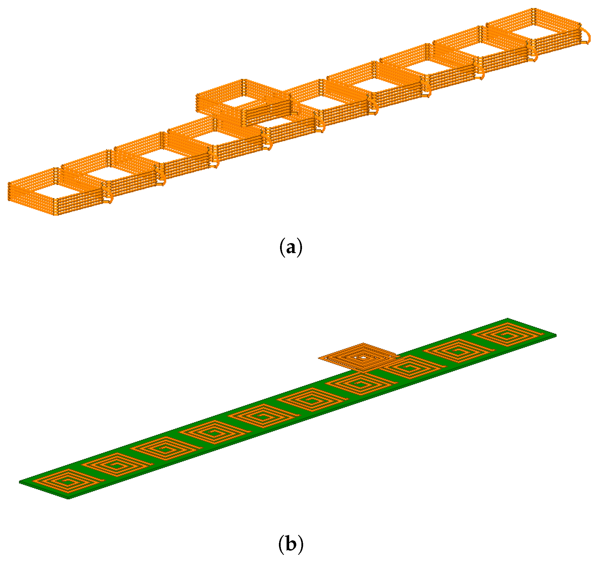
Figure 1a shows an example of a wound coil array, whose copper wire coils allow the circulation of considerable currents. The system can be exploited for both power transfer and position detection. In
Figure 1b, a PCB printed array is depicted. Its coils can have very small dimensions, and it can be adapted to applications of all kinds and is particularly robust and noninvasive.
In
Section 2, from a circuit analysis of these systems, an analytical expression of the input impedance of a resonator array coupled with an external resonator placed in a generic position is presented, while in
Section 3, the trend is analysed for different coil parameter values. This analysis is the prelude to a discussion on the design criteria, based on which it is possible to dimensionalise the sensor so that it achieves the required performance in terms of accuracy and resolution.
Section 4 then discusses the uncertainty of the estimated impedance (from the voltage and current measurements) and how this is reflected in the longitudinal position inaccuracy, considering a discrete implementation.
2. System Circuit Modelling
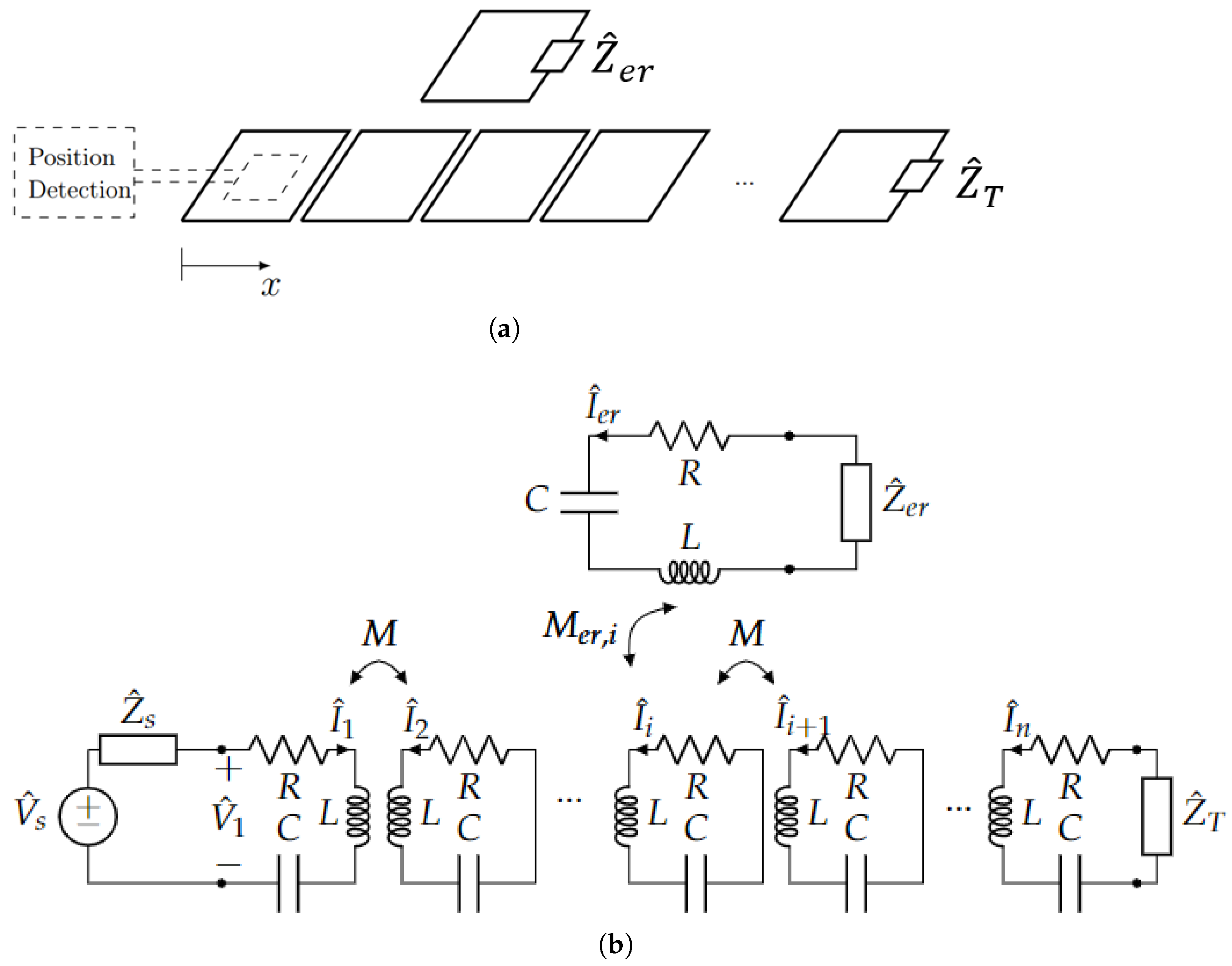
The system presented in this paper is composed of a resonator array with an additional resonator over it (moving or standstill) as is schematically illustrated in
Figure 2a. The position of the moving resonator along the array is identified with the variable
x. The array is composed of
n identical and equally spaced coils along
x, so that the mutual inductance
M between each pair of adjacent coils is the same and all cross couplings between nonadjacent cells are neglected, according to the so called “nearest-neighbour approximation” [
24]. The coils feature a resistance
R and a self inductance
L and resonate with a series-lumped capacitor of capacitance
C at the frequency
. In order to minimise ohmic losses occurring in the windings, the coils are usually designed with a large cross section which, at the same time, provides a large quality factor
Q. We see at the end of
Section 3 that an excessively large factor of merit should be avoided and that input impedance curves are better distinguished with lower
Q values.
Due to the topology of the system, the best choice for the additional resonator is a moving coil of the same size as, or slightly smaller than, the array resonators. In fact, a larger coil would couple with more array cells, at the same time compromising the spatial resolution and impeding the occurrence of “perfect alignment” positions. Thus, for simplicity, a moving coil identical to the array resonator cells is considered. The moving resonator can be placed at any position along the array, and the mutual inductance between the moving resonator and the generic
ith resonator of the array varies according to the moving resonator position
x. Since the mutual inductance coefficients between the external resonator and the facing cells depend on the resonator position, a relative coordinate
may be defined as
where
x is the absolute coordinate along which the array lies,
i indicates the first array cell facing the external resonator, and
d is the resonator size in the
x direction (as mentioned, taken as equal to the size of the single cells of the array).
Moreover, additional loads are added to both the external resonator and the last array cell,
and
, respectively (see
Figure 2a). They provide two degrees of freedom, which can modify the behaviour of the system and are crucial for the accuracy of position sensing, as discussed later.
The system is excited in the first array resonator with a sinusoidal voltage at the resonant frequency , and thus, it is possible to consider all currents and voltages as phasors at the angular frequency . Under this hypothesis, it is possible to define the impedance of each cell of the array as , where the termination impedance must be added for the latter as , and the impedance of the external resonator should be . In resonant conditions, they reduce to , and , respectively.
The behaviour of the system can be described with a set of
Kirchhoff voltage law (KVL) equations, one for each array resonator, that include the relevant component equations. Considering the moving resonator coupled with both the
ith and
th cells of the array and a real voltage source connected to the first cell, a system of KVL equations can be written as
with one additional KVL equation for the receiver:
By solving this system of equations, it is therefore possible to calculate the current of all resonators under the conditions specified by the parameters. It is evident that the position of the receiver affects the KVL equations (through the mutual inductance ) and, in turn, the resulting current. In general, the system must be solved for each receiver position.
Input Impedance of a Resonator Array with an External Coil
The input impedance of the system can be studied by resorting to the introduced circuit model, described by the equation system (
2). The input impedance of the array
at the resonant frequency of the cells for a certain position
x of the external coil can be defined as the ratio of the input voltage
and current
phasors at the frequency
:
and, referring the input voltage to the source voltage
, it yields that:
The analytical expression of the input impedance can be obtained by reducing (
2) to one equation and, in particular, to the one referred to in the first resonator. This is possible by substituting the one relevant to the adjacent resonator in each equation, starting from the
nth one (the rightmost one) in our circuit. Thus, (
2) reduces to
where
corresponds to the equivalent impedance seen in the first cell of the array with the external coil coupled with the
ith and
th resonators.
The array input impedance results in the recursive formula:
where
and
The impedance terms (
9) are usually called “defect impedances” and correspond to the reflection impedances of the receiver to the facing array resonators. In general, for each couple of facing resonators,
i and
, the input impedance of the system can be defined as a continuous function of space. This kind of function is known as a “continued fraction”, which is a recursive formula that can be calculated through an iterative process. Thus, it is difficult to express it as a function of the absolute coordinate
x, since the continued fraction changes its form depending on the receiver’s position.
To the best of the authors’ knowledge, no closed analytical expressions are known for expressions of the type (
7) for any position of the receiver. However, this kind of expression can be easily computed numerically by means of computers or embedded systems (e.g., exploiting modern digital signal processors). For simplicity, the array input impedance of (
7) for a generic receiver position
x is considered and indicated as
.
Due to the presence of an external coil coupled with the array resonators,
generally presents complex values, even when the system is excited at its resonant frequency, while the input impedance of a resonator array without any external coil is purely real [
12,
24]. Considering all cells operating in perfect resonance, the internal impedance
and the defect impedances
,
, and
of (
9) are purely real, while
is complex. This can be explained by considering that the presence of the moving coil introduces further coupling between the resonators it faces with a consequent phase delay in the impedance seen from the array input port.
According to [
22], for a certain array, both the magnitude and the phase of the input impedance oscillate depending on the external coil position. In particular, while the magnitude is always positive, the angle can be positive or negative, therefore meaning
can present with either inductive or capacitive behaviour depending on the
x coordinate.
The trend of the input impedance strongly depends on the parameters of the array. In general, to preserve the periodicity and symmetry of the structure, all coils are identical, so they are characterised by the same parameters. can be adjusted by acting on the termination impedance and the external resonator impedance . The optimal values of and must be chosen to achieve the desired trend and fulfil the requirements of the specific application.
3. Resonator Array as a Linear Position Sensor
As discussed in the introduction, the unique behaviour of the input impedance can be exploited to determine the position of an external resonator coupled with the array. By feeding the first array resonator with a sinusoidal voltage
(whose phasor is indicated as
) at the cell’s resonant frequency
, the input impedance of the array can be estimated for any position of the external coil as
where
and voltage
are the phasors of the measured input current and voltage, respectively, at the resonant frequency. The symbol “∼” denotes the estimated quantities.
In addition to the voltage source, a system for measuring the current and voltage of the first resonator of the array is therefore necessary. Knowing the internal impedance
of the voltage source, it is possible to determine the input impedance of the array by measuring the input current:
In order to identify the absolute position of the external coil, it is necessary for the
function to present a one-to-one behaviour with respect to the position
x (a so-called “bijective” function), i.e., each value (even complex) of
corresponds to a unique value of
x, and there is complete mapping between the two domains.
The resistance of the resonator windings is usually undesirable in resonant systems, since it leads to power losses and thermal heating. However, it guarantees the convergence of to finite values and makes them different for any moving coil position, in particular when moving from one cell to another along the resonator array. Indeed, both the magnitude and phase of the equivalent impedance are attenuated as the moving coil is positioned far from the array input resonator, and the combination of their values is unique for any position x of the moving coil. Thus, once the array parameters have been fixed, the measurement of the array input impedance allows the estimation of x. The coils are designed to maximise the self and mutual inductances, and then, the value of the resistance is consequently found. The remaining degrees of freedom are the array coil number n, their size d in the x direction of the space, and the impedances and .
3.1. Design and Choice of Array Parameters
The size and arrangement of the coils must be adapted to the system in which the sensor is to be installed, and it is therefore essential to determine the requirements concerning the full-scale range, accuracy, and sensitivity.
The full-scale value of the sensor is closely related to its specific application and must be established during the design or installation phase. It basically corresponds to the overall array length . It is, in fact, possible to build modular arrays that can be configured in the field (arrays on flexible PCBs that can be cut and fixed to the structure and to the object whose translational position is to be measured).
The basic accuracy of the location is instead mainly affected by the number of coils, which determine the periodicity and therefore the trend of the input impedance of the array. It can be observed that the portion of space in which the sensor has to operate can be covered by an arbitrary number of resonators, which determines the number of periods of (the larger the number the shorter the length). Having a larger number of periods improves the location accuracy, because for the same amount of translational movement, the observed variation of is greater as it moves through many complete turns of its phase.
Once the array length has been chosen, the number of coils n is clearly related to the dimensions () which, in turn, affects the trend of the mutual inductance . Theoretically, since the space variation of is continuous, an array composed of at least one resonator could be sufficient to make the sensor operate. However, the moving coil length has to be greater than half of the array resonator length; otherwise, will be symmetric with respect to x, and it will not be possible to distinguish whether the moving coil covers the first or second half of the resonator. In practical applications, it is convenient to reduce the length of the moving coil and adapt it to the size of the object to which it is fixed. In this way, it is possible to cover the entire area of movement of the object without altering the size of the moving coil.
It is worth mentioning another aspect that should be addressed in the design stage, which is the cell resonant frequency
. Its major impact is on the mutual impedance
between the resonators, as shown in (
7), in particular, at the highest frequencies. The value of
affects the value of the impedance function, even if does not alter its behaviour. In addition, an increase in
allows the use of smaller capacitors, making the system lighter and cheaper. However, it must also be observed that this leads to an increase in the coil resistance
R due to skin and proximity effects. These effects can, however, easily be taken into account, and the proposed discussion on the sensor design is not affected. In general, the design choices are the result of a compromise that depends on the type of application.
3.1.1. Sensitivity
To effectively evaluate the accuracy of position detection, it is convenient to introduce sensitivity parameters, defined as the variation in the input impedance per unitary variation in the longitudinal direction
x. Since
is a complex value function, its sensitivity to space variation is defined for the amplitude and the phase as, respectively,
and
Intuitively, it is clear that the larger the values, the greater the accuracy of the measurement. However, it is important to note that if the sensitivity values are too high, the sensor may be required to evaluate very small or very high impedance values, resulting in the necessity of covering large dynamics, unnecessarily complicating the measurement system. The sensitivity is mainly affected by the space variation in the mutual inductance
, which contributes to
, as it is possible to see from (
9) and (
7).
Finally, it can be observed that the minimum step is fixed by the discretisation step used to calculate the mutual inductance function . When the geometry of the array coils allows to be calculated analytically, theoretically, , and the minimum step should be fixed by the accuracy of the current sensor and the computational burden (depending, in turn, on the DSP capability).
Overall, once and have been defined, the number of coils can be chosen according to the length and the sensitivity parameters and .
3.1.2. Termination Conditions
The termination impedances
and
are chosen to be real values to avoid the alteration of the coil resonant frequency. Specifically, the short-circuit (SC), open-circuit (OC), and matching terminations have been considered, being the typical ones for resonator arrays [
12,
25]. They correspond to
,
, and
(the latter is used for low-loss arrays operating at the cell’s resonant frequency), respectively.
As a first consideration, it should be noted that an OC termination of the array is completely useless, since the last resonator does not interact with the others, and thus, the presence of the moving coil over there is not detected. Moreover, the behaviour of is the same as when the array is considered to be shorter by one resonator. Thus, a consistent choice should be .
Concerning
, a similar discussion can be made. The limit cases are
(equivalent to a SC condition) and
(equivalent to an OC condition). The former choice leads to large values for the defect impedances defined by (
9), and thus, for the array input impedance as well. Depending on the position of the external coil, the defect impedances contribute to
differently (see (
7)). The latter case leads, instead, to null defect impedances, which no longer have any effect on the array response, thus making sensing via the input impedance impossible.
It is thus reasonable to choose a real value for
, depending on the resulting input impedance trend. As a reference value, it is possible to use the external coil matching impedance discussed in [
18], which is calculated by considering the external coil (in [
18], referred to as the “receiver”) as an array made from a single cell connected to the effective resonator array. It is defined as
. It is important to note that there are no recommended values to use and that the impedances
and
(being the degrees of freedom of the system) can be chosen directly in the field during system calibration.
As a last consideration, it is evident that the largest array input impedance values are found for (external coil coupled with the first cell), since the defect impedances directly affect the coil connected to the impedance measuring apparatus (basically the current sensor and the voltage source). Having values that are too large may complicate the tuning of the current sensor, since the range of values that should be measured is excessively widened.
Overall, the convergence and univocity of the equivalent impedance function can be verified from its trajectory in the complex plane, which should be limited and should not present intersection points. This approach is adopted in the following discussion.
3.2. Case Study
As a case study, the 10-cell resonator array depicted in
Figure 1b was considered. The parameters of the resulting system are listed in
Table 1.
In [
22], different complex values of
were considered (both inductive and capacitive), focusing on a range of possible loads for the receiver coil for a power transfer application (moving electric vehicle); the resonator array laid on the driving lane was configured with typical termination values. However, in this study, we considered a purposely developed position sensor in which both
and
can be used as degrees of freedom in order to optimise the performance. As already mentioned, to avoid the alteration of the resonance frequency of the coils, it is convenient to choose real impedance values.
For the design of this sensor, the behaviour of the input impedance of the considered 10-cell array was evaluated by considering a SC, OC, and the matching terminations and external coil impedance values of , , and . To highlight the effect of the resonator resistance (and thus the resulting quality factor Q), the simulations considered the resistance of the coil only, providing a quality factor at , and the presence of an additional series resistor adjusted to at the same resonant frequency.
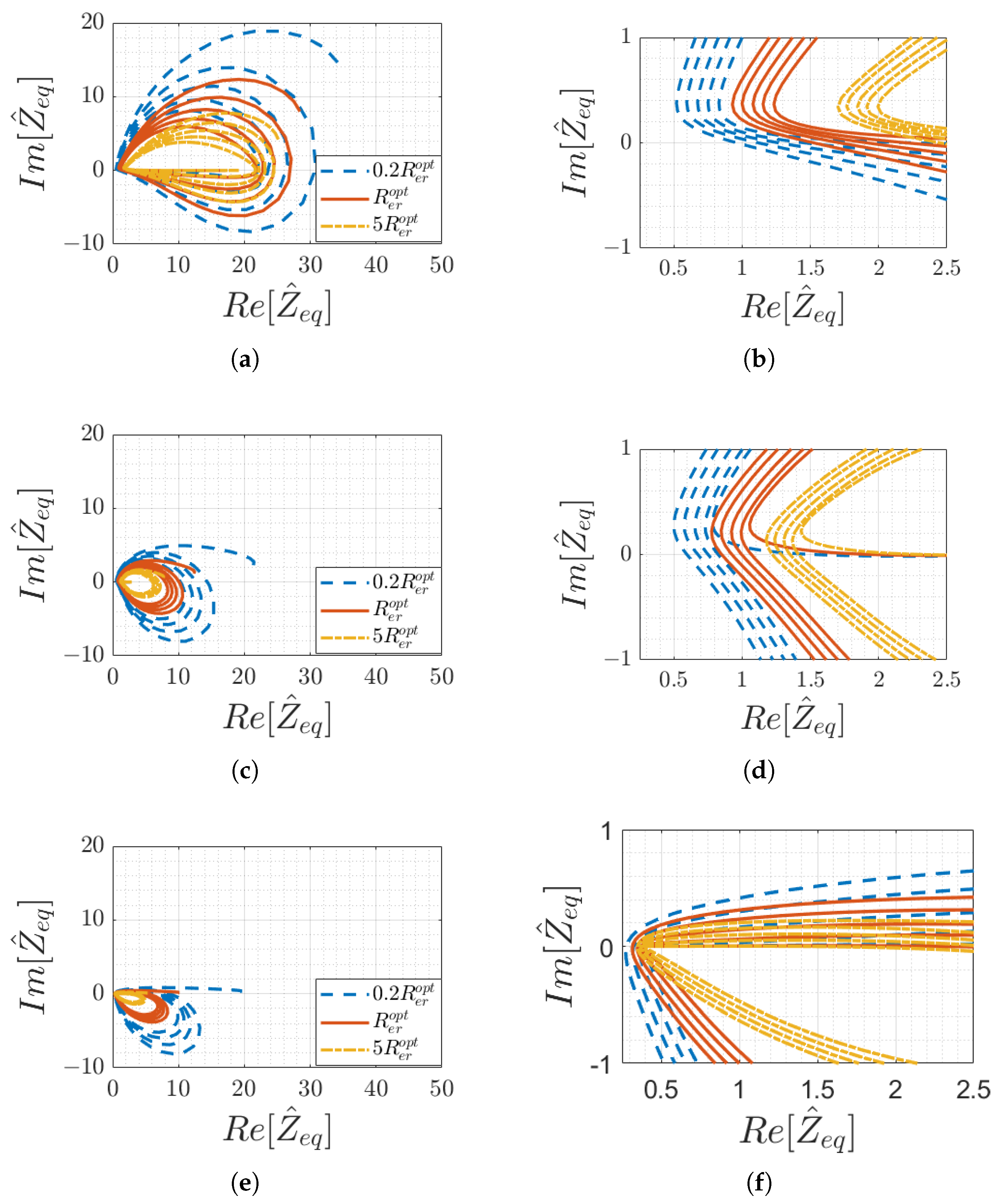
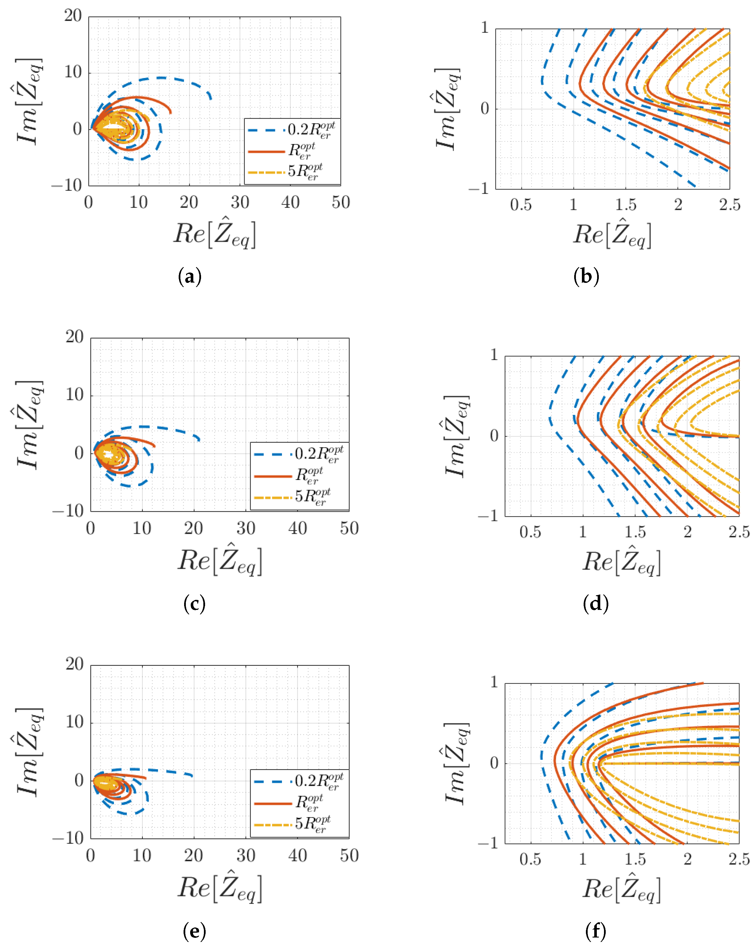
The trajectories of the input impedance in the complex plane are plotted in
Figure 3 and
Figure 4 for
and
, respectively, as a function of the external resonator position for different load values
for short-circuit (SC), matched, and open-circuit (OC) terminations of the array, respectively.
The trajectories perform cycles in the complex plane which, therefore, indicates that both the magnitude and the phase of oscillate between relative maxima and minima, depending on the position of the external coil. The plots clearly show that, whatever the parameters of the system are, the input impedance always has a positive real part (as expected, being a passive system), whereas the imaginary part oscillates between positive and negative values. The array exhibits globally capacitive or inductive behaviour, depending on the position of the external coil. This characteristic does not affect the operation of the sensor, since both the analytical calculation and the measurement of can be performed for any value of the input impedance angle.
This periodicity is analogous to that described in [
22,
24], where it is illustrated that with real values of
, the input impedance is real if the external coil is aligned with an array resonator (the phase angle is zero). Then, for these positions, the magnitude values depend on the specific number of resonators and the array termination.
For the purpose of sensing the external coil position
x, the main requirement is to obtain an input impedance function that has unique values for each position
x. This behaviour can be clearly deduced from its trajectory in the complex plane. However, each of these curves tends to have intersections for some positional values. By observing their zoomed-in views in
Figure 3 and
Figure 4 (specifically,
Figure 3b,d,f for
and
Figure 4b,d,f for
), it can be seen how it is instead possible to avoid this superposition by choosing suitable load and termination impedance values.
In particular, for the 10-cell resonator array considered in this analysis, the curve that best satisfies this requirement is obtained with
and
(matching), as depicted in
Figure 3a,b for
and
Figure 4a,b for
.
The role of the quality factor of the coils can be appreciated by observing the extent of the area covered by the trajectories in the complex plane: the smaller the
Q, the smaller the module of the function
. This occurs because low-quality factors indicate high resistance in the coils, which affects the denominators of the recursive function (
7). For the purpose of external coil sensing, the optimal quality factor should present much smaller values than those required by coils for power transfer (which have
).
Overall, the best choice for the 10-cell array considered in this study is to use , (matching) and . With proper optimisation algorithms, it is clearly possible to improve the calculation of the values of and . In mathematical terms, the goal is to maximise the minimum difference (considered a complex difference by choosing an appropriate norm in the complex space) between the values of the function for different x values, separated by the minimum detectable movement, which corresponds to the accuracy of the spatial position determination.
3.3. Effect of the Distance between the External Coil and the Resonator Array
In general, the sensor can operate for any vertical distance
h of the external coil (with respect to the array of resonators) as long as this is coupled with the facing cells of the array. Specifically, the mutual inductance between the external coil and the array resonators must differ from zero. However, for different
h values, the function
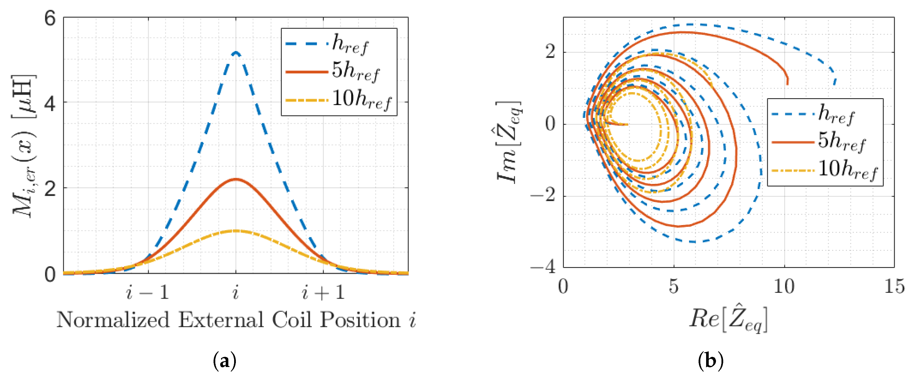
may present different values (even if the behaviour is the same), and it is necessary for the current measurement system on the first resonator to work adequately. In
Figure 5a, the mutual inductance
between the
ith array resonator and the external coil is plotted as a function of the (normalised) positions
x for different vertical distances. For a fixed position, the mutual inductance value decreases as the distance between the external coil and the array increases. As a consequence, the input impedance function is “less affected” by the presence of the external resonator and its value changes.
Figure 5 shows the trajectory in the complex plane of the input impedance function for different distances
h for the case of matched termination and an optimal external resonator load (that is, the best configuration for the considered array, as previously concluded in
Section 3.2). It particular,
refers to a distance of 2 cm.
As expected, the input impedance function has a similar trend for the three cases, although the values for a given position x are different. Overall, as the vertical distance increases, the values of the input impedance become smaller. Similarly, the difference between the impedance magnitude or phase for two consecutive positions x (described by the sensitivity functions) reduces, requiring more accurate current and voltage sensors in the measurement apparatus. It can be concluded that
Theoretically, the sensor can work as long as the mutual inductance differs from zero (and, thus, the input impedance varies with x);
Practically, the vertical distance h is limited by the accuracy of the measurement system, which should be able to detect the magnitude and phase variations for the different positions x;
Qualitatively, by inspecting the results shown in
Figure 5, even in the
case ( 20 cm), the changes in impedance with each periodic variation can be visually distinguished, and the necessary accuracy is in the order of few percent, which is achievable with off-the-shelf devices for current and voltage measurement.
4. External Coil Position Detection
Considering the system operating in resonance, the resonator impedance presents a positive real part only, which is due to the winding resistance of the coils, making the values of the array input impedance differ for each moving coil position
x. Indeed, while both the magnitude and phase of
can have the same value for different
x values, their combination is unique for a certain
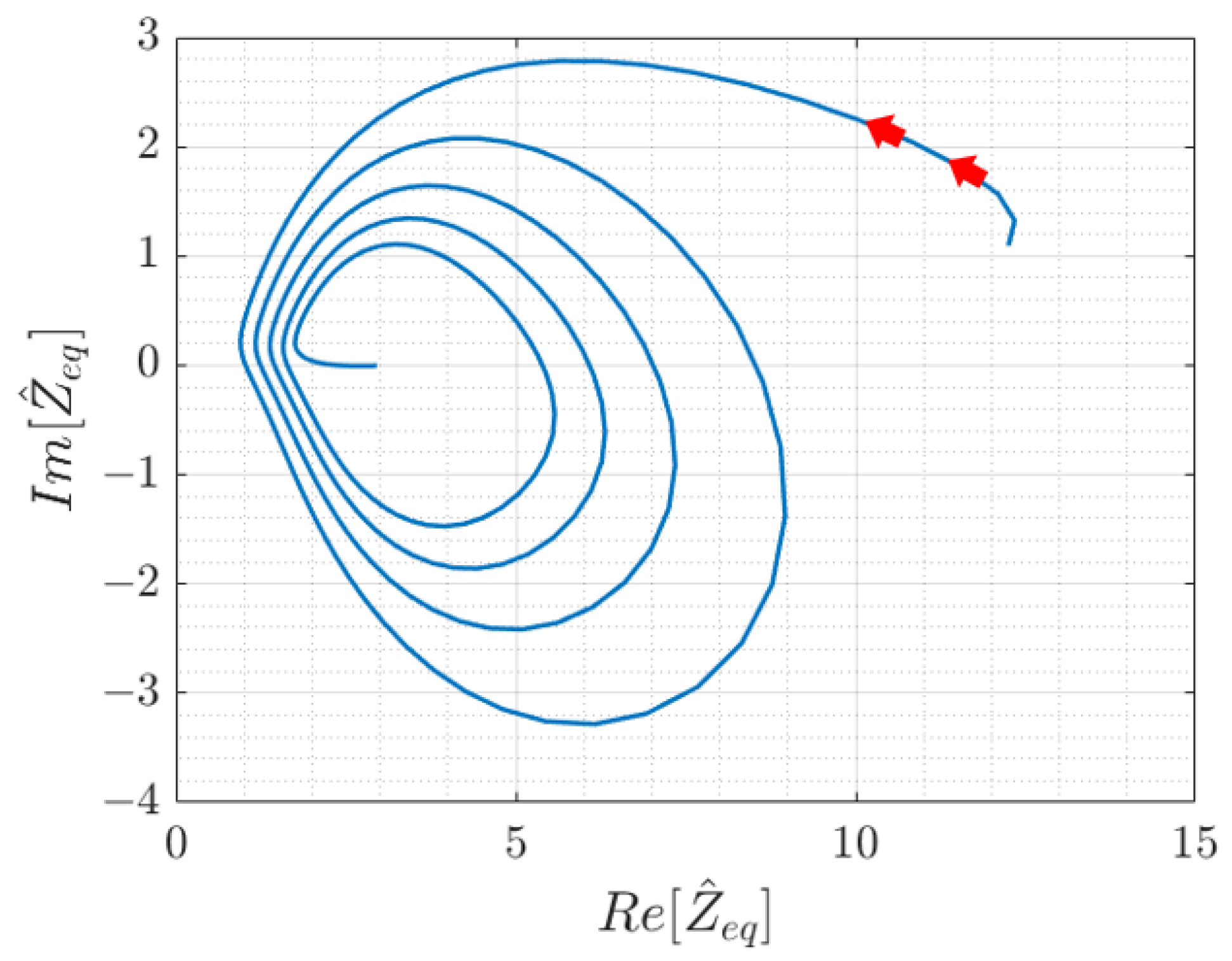
x. For the set of parameters of the considered 10-cell array in the previous example, this can be appreciated from
Figure 6, which shows the trajectory of the input impedance function in the complex plane according to the moving coil position
x for certain values of
and
. There are no intersections in the amplitude phase plot.
The input impedance can then be estimated according to (
10) by feeding the first array resonator with a sinusoidal voltage
at the resonant frequency
and measuring the current circulating in the same resonator
.
Then, by comparing the estimated and (theoretically) calculated values, it is possible to determine the moving coil position x. In particular, the calculated impedance should match the measured one within a level of tolerance.
The conditions to be satisfied can be written as
where
and
are the tolerance margins accepted for the magnitude and phase equalities, respectively.
is assumed to be numerically calculated with a discretisation step
, and thus, as a consequence, all parameters defined according to
are affected by the choice of
. In particular, the discrete formulation of the sensitivity provided in (
12) and (
13) can be written for a certain value of the (discretised) space coordinate
, considering the difference quotients:
With
spiralling to lower values for increasing
x value, as shown in
Figure 6, these expressions clearly indicate that, assuming a fixed space interval
, the sensitivity of the input impedance is different for each
. This suggests the need to define variable tolerance margins that should be larger when the sensitivity is higher (this has also a practical justification).
, being a bijective function, has no crossovers and its values are always distinct, so under an ideal perspective, it is, in principle, possible to determine the present position with a single measurement with infinite accuracy. Two factors hinder such a straightforward solution:
For the latter, starting from the standard uncertainty of the voltage and current readings at the resonance frequency,
and
, we can define a corresponding uncertainty for the estimated
by distinguishing the amplitude and phase. Let us consider the magnitude and phase of
and
to be
and
and
and
, respectively. We know that the amplitude and phase of
are determined by
Assuming then that the two measurements of voltage and current are uncorrelated or weakly correlated (as some common influence from environmental factors, for example, cannot be ruled out completely), the uncertainties may be calculated by ignoring the crossed terms:
The two uncertainties on the magnitude and phase of must then be divided by the two calculated sensitivities in order to derive the expected uncertainty on the position value which, in turn, determines the minimum acceptable discretisation step .
In general, it is required that
and thus, the discretisation step must be chosen to be small as possible, such that
It is worth mentioning that, when the required
does not satisfy (
22), it is possible to increase the number of coils
n, so that
and
increase for the same
.
5. Conclusions
The possibility of employing resonator arrays with a receiver as a passive sensor for object location has been proposed and discussed. This is applicable to any scenario of a longitudinally extended structure (e.g., a supporting structure, such as a track) and a translating object, as well as to rotational scenarios. A longitudinal array structure of magnetically coupled resonators is attached to the fixed structure and magnetically coupled to the external coil attached to the moving object. The position is then estimated by measuring the array input impedance. This is possible with a simple high-frequency impedance measurement system consisting of a sinusoidal excitation source at the resonance frequency and a current and voltage sensor at the array input port, supported by computational resources for signal postprocessing and impedance estimation.
The resonator array can be built with any slim, flat structures, such as wounded coils or even printed circuit board circuits. It is also suitable for application in a considerable longitudinal extension. It is advisable for the size of the external resonating coil attached to the moving object to be the same as that of the cells in the array to improve the spatial accuracy. A coil that is too large, besides being cumbersome, would couple with many array cells, making the impedance function ambiguous and its determination more difficult.
A specific case study that considered a resonator array with 10 cells was considered. Based on the resulting parameter values, a discussion on the required voltage and current measurements highlighted that simple and cheap sensors and transducers are needed. This technique can be implemented in arrays specifically developed as position sensors, which can be introduced into systems with moving mechanical parts. Attention should be paid when there are metal parts in the surrounding structure, which can modify the parameters of the resonators. It is, however, possible to consider these variations in the sensor calibration phase, which can be facilitated by acting on the load and termination impedances. A range of values for the array cell resistance (to determine the factor of merit at the resonance, it should be desirably low, at least smaller than 100) and the array termination (the matched impedance termination provides the best results, as discussed at the end of
Section 3) was discussed.
Requiring little power and cheap components, it is therefore possible to create arrays with inductors printed on flexible PCBs, which can be easily installed on both translational and rotational systems and that are robust from environmental and mechanical viewpoints.
