Abstract
A high performance bulk-driven rail-to-rail fully differential buffer operating from ±0.3V supplies in 180 nm CMOS technology is reported. It has a differential–difference input stage and common mode feedback circuits implemented with no-tail, high CMRR bulk-driven pseudo-differential cells. It operates in subthreshold, has infinite input impedance, low output impedance (1.4 kΩ), 86.77 dB DC open-loop gain, 172.91 kHz bandwidth and 0.684 μW static power dissipation with a 50-pF load capacitance. The buffer has power efficient class AB operation, a small signal figure of merit FOMSS = 12.69 MHzpFμW−1, a large signal figure of merit FOMLS = 34.89 (V/μs) pFμW−1, CMRR = 102 dB, PSRR+ = 109 dB, PSRR− = 100 dB, 1.1 μV/√Hz input noise spectral density, 0.3 mVrms input noise and 3.5 mV input DC offset voltage.
1. Introduction
Biomedical wearable and implantable systems are becoming widely used to sense and monitor biological signals such as EEG, ECG, respiratory signals, etc., in real time [1]. The electronic circuitry used in these systems requires very low power dissipation PQ < 1 uW and very low supply voltages Vsupply < 1 V [2]. In order to preserve battery life and/or to be able to operate with energy harvested sources in biological systems, these systems operate transistors in subthreshold and use bulk-driven circuits, where the input signals are injected through the bulk terminals rather than through the gate terminals [3]. To suppress large noise from digital and other analog sections of the chip and to increase dynamic range, analog signals on chips are usually processed using fully differential circuits.
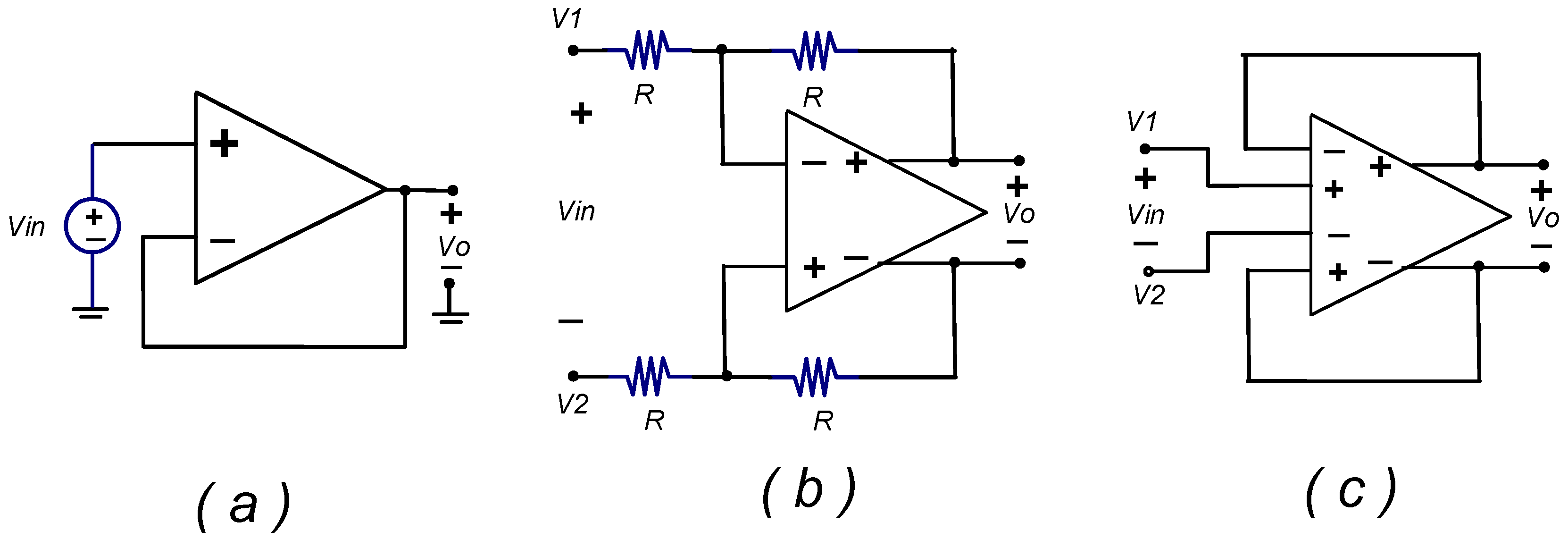
An important building block of analog systems is the analog buffer that is required to have very low output impedance Rout ≪ RL, very high input impedance Rin ≫ Rso and close to unity gain G = Vout/Vin = 1 (Rso is the signal source impedance). The buffer is commonly used as an interface between subsystems on a chip or to bring signals out of a chip. The op-amp is commonly used to implement buffers. Figure 1a shows the conventional implementation of a single-ended voltage buffer based on the non-inverting op-amp configuration. A drawback of fully differential op-amp circuits is that they can only be used to implement inverting configurations with finite input impedance Rin. Figure 1b shows a possible implementation of a fully differential buffer using four equal valued resistors R. This requires the value of R to be in the order of tens of MΩs to avoid loading the signals sources that have typically impedances Rso in the order of MΩs for micropower circuits operating in subthreshold. These resistor values are impractical due to the large silicon area required for their implementation and to the large time constants associated with them that degrade the circuit’s bandwidth. Another drawback is that the BW of a unity gain inverting buffer corresponds to one half of the gain bandwidth of the op-amp (BW = GB/2) as opposed to the voltage buffer based on the non-inverting configuration that has a factor two higher bandwidth BW = GB. Figure 1c shows the implementation of a true fully differential buffer using a fully differential op-amp with a differential–difference input stage [4,5,6] that has two pairs of input terminals.
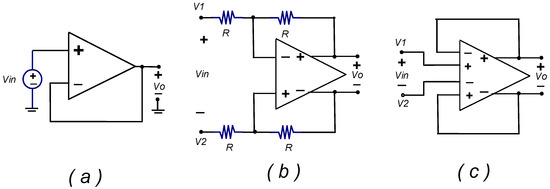
Figure 1.
(a) Single-ended buffer based on non-inverting configuration; (b) fully differential unity gain amplifier with finite input impedance 2R based on conventional fully differential op-amp; (c) true fully differential analog buffer based on FD-DDA with infinite input impedance.
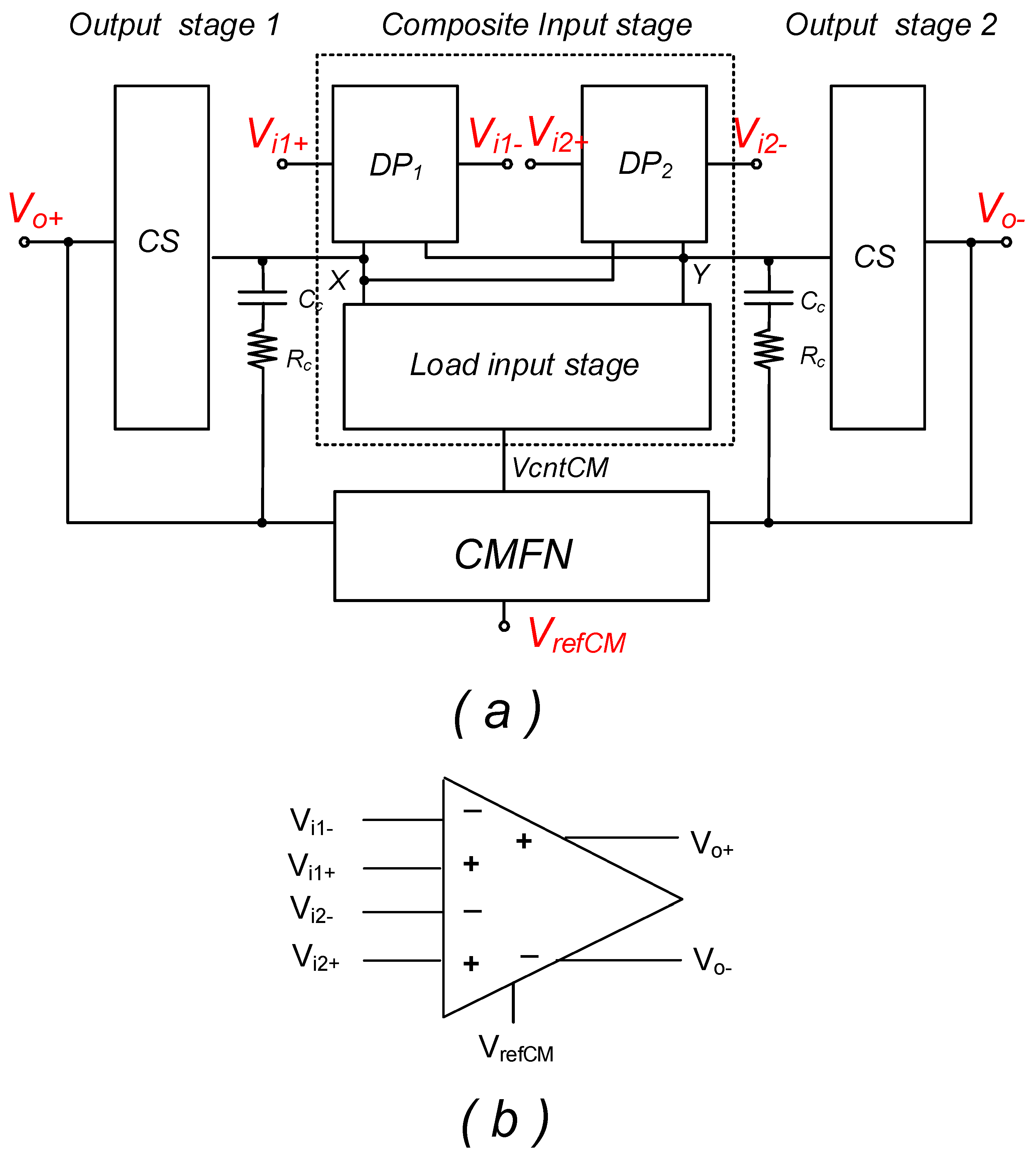
Figure 2 shows the architecture of a fully differential Miller op-amp using a differential–difference input stage (denoted here FD-DDA). The input stage has two differential pairs with two pairs of input terminals Vi1+, Vi1−, Vi2+ and Vi2−, a common load for the input stage, two output stages and a common-mode feedback network. Upon application of negative feedback, the virtual short-circuit input rule of a conventional op-amp (Vi+ − Vi−) = 0 is simply replaced by the composite virtual short circuit input rule: (Vi1+ − Vi1−) + (Vi2+ − Vi2−) = 0 in the differential–difference input stage [4]. In this paper the output stage operates in class AB based on the Free Class AB Technique reported in [7] as explained in detail in Section 3.
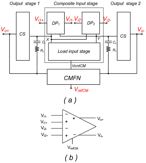
Figure 2.
(a) Architecture of fully differential Miller op-amp with DDA input stage; (b) FD−DDA symbol.
The buffer of Figure 1c is a true fully differential buffer with infinite input impedance. It does not require external resistors; therefore, signal sources VS+, VS− are not loaded by the buffer. Since it is based on a non-inverting configuration, the bandwidth of the buffer corresponds to the gain bandwidth of the op-amp, as opposed to the circuit of Figure 1b that has half the bandwidth. Negative feedback results in the input terminals having voltages V1 = Vs+ = Vi1+ = Vi1− (V2 = Vs− = Vi2+ = Vi2−). These voltages follow the swing of the input signals VS+ (VS−) similar to the case of the conventional single-ended buffer of Figure 1a. A drawback of gate-driven non-inverting op-amp circuits operating from low supply voltages (Vsupply < 1 V) is that the peak-to-peak input signal swing VPPswing is severely limited by the differential pair headroom HRDP = |VGS| + |VDSsat|. The input swing is given by VPPswing = Vsupply − HRDP (VGS and VDSsat are the gate-source and drain-source saturation voltage of the transistors in the input differential pairs). Bulk-driven differential amplifiers can operate with rail-to-rail input signals in low-voltage circuits [8,9,10,11,12,13,14,15,16,17,18,19,20,21,22,23]. The condition Vsupply < 1 V is usually imposed in bulk-driven circuits to avoid forward biasing the bulk–substrate PN junctions of the bulk-driven differential pair input transistors. These circuits are usually operated in subthreshold.
In this paper, we show the implementation of a high performance fully differential buffer with rail-to-rail input and output swing based on a bulk-driven FD-DDA implemented using a high CMRR no-tail bulk-driven pseudo-differential cell.
2. High CMRR Bulk-Driven No-Tail Pseudo-Differential Pair
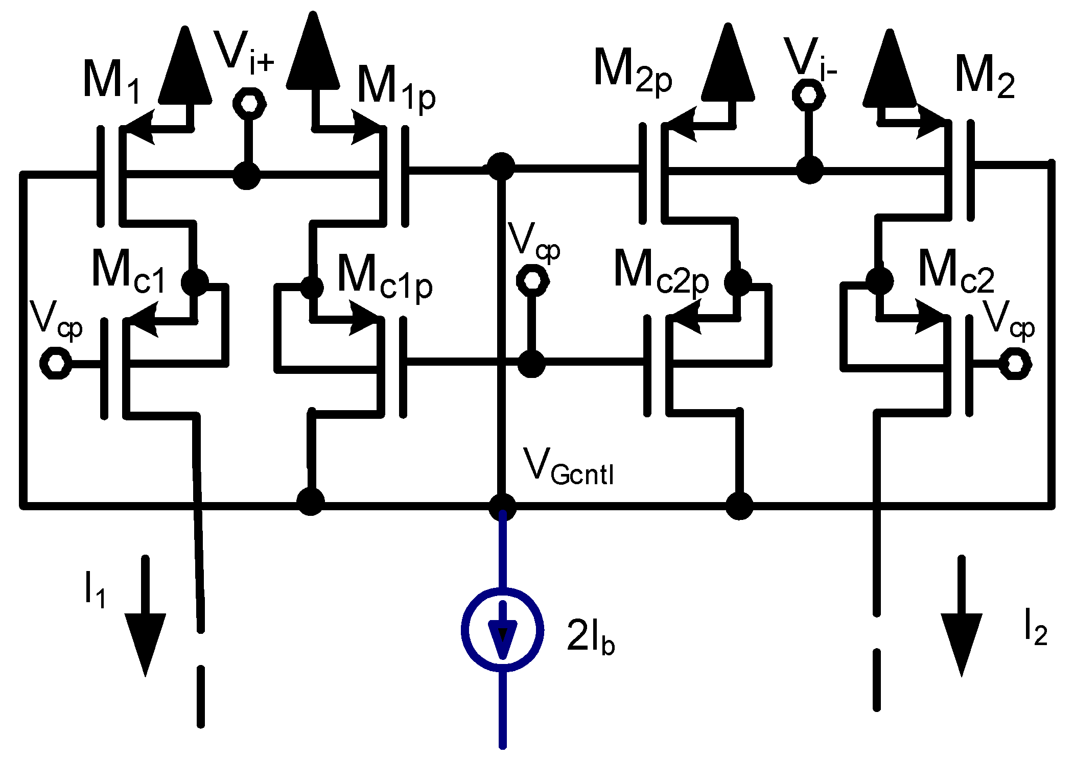
Figure 3 shows the schematic of a bulk-driven no-tail pseudo-differential pair cell. The input terminals Vi+, Vi− can have rail-to-rail swing. This cell is used to implement the two input pseudo-differential pairs of the differential–difference input stage and the common-mode feedback network of the proposed fully differential DDA with low supply voltage requirements, rail-to-rail input and output range, high CMRR and class AB operation. The cells include a high gain negative feedback loop through VGcntl that provides it with high common mode rejection as explained below. All transistors in the circuit of Figure 3 operate in subthreshold in high gain mode with gmro >> 1.
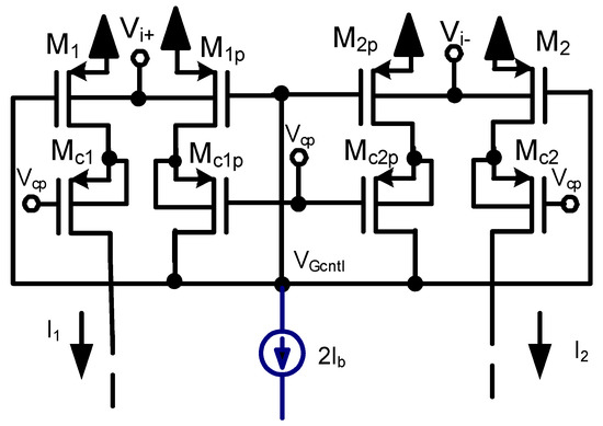
Figure 3.
Low supply voltage bulk-driven class AB no-tail cascaded pseudo-differential pair with rail-to-rail input range and high common mode rejection ratio. The biasing current source 2Ib is also implemented as a cascoded current source.
2.1. Differential Gain
Assume complementary input voltages Vi+, Vi−. In this case, for positive values of the input differential voltage Vd, the voltage Vi+ = Vd/2 increases and Vi− = −Vd/2 decreases by the same amount. Drain currents in M1, M1p decrease by–ΔID = −gmbVd/2, and drain currents in M2, M2P increase by the same amount ΔID = gmbVd/2. Since the sum of currents in M1p, M2p remains constant and equal to 2Ib the voltage VGcntl at the gate of M1, M1p, M2, M2p has only relatively small variations that compensate for channel-length modulation effects. The effective differential transconductance gmd has an approximate value gmd = gmb = (I1 − I2)/Vd.
2.2. Common-Mode Gain
Assume now common-mode input voltages Vicm = Vi+ = Vi−. Given that M1p, M2p satisfy the condition 2Ib = I1p + I2p, negative feedback adjusts the voltage VGcntl so that the condition Ib = I1p = I2p = I1 = I2 is satisfied. Transistors M1, Mc1p and M2, Mc2p constitute high gain cascode amplifiers that provide a gain A = (gmro)2 to the local negative feedback loop (gm and ro are the small signal transconductance gain and output resistance of the MOS transistor assumed, for simplicity, equal for all transistors). In this case, all currents (I1p, I2p, I1, I2) remain constant, and the output differential current should be Iout = I1 − I2 = 0 which corresponds ideally to a zero common mode transconductance gain. In practice, however, the finite gain Afb = (gmro)2 of the loop formed by M1p, Mc1p and M2p, Mc2p leads to a non-zero common mode transconductance gain gmCM given by gmCM = gmb/(gmro)2, The systematic common mode rejection ratio is given by CMRRsyst = gmd/gmCM = 1/(gm1ro)2. Other authors (i.e., [8,9,10]) have used non-cascoded no-tail bulk-driven pseudo-differential pairs which are characterized by much lower CMRR.
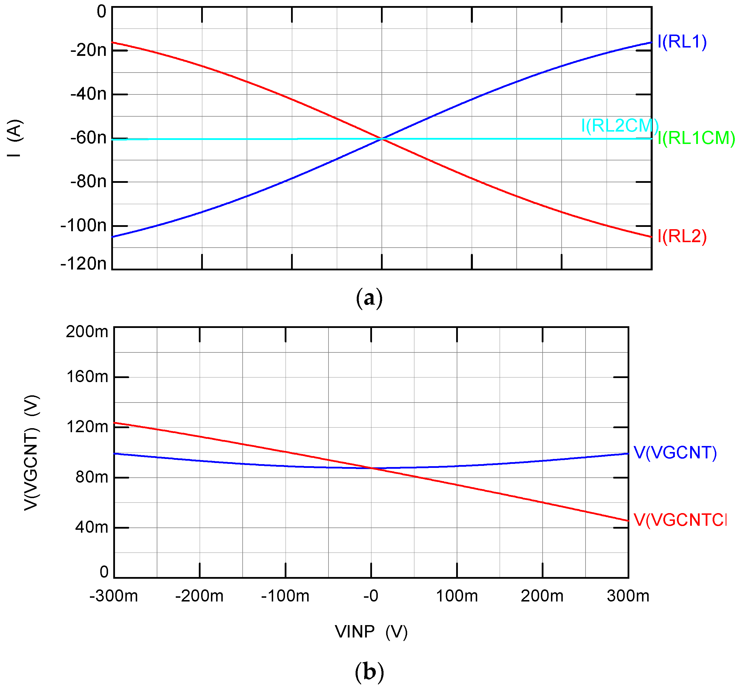
Figure 4a shows the currents in M1 and M2, denoted IRL1 and IRL2, for complementary differential input voltages and denoted IRL1CM, IRL2CM for common mode input voltages. Figure 4b shows the value of VGcntl for differential input voltages and VgcntCM for common mode input voltages. Notice that the bulk-driven pseudo-DP cell has high CMRR. It shows no noticeable changes in IRL1CM, IRL2CM for common mode input voltages, while VgcntCM has relatively large changes that keep the current in M1, M2 approximately constant. On the other hand, currents IRL1 and IRL2 are subject to relatively large complementary changes, while VGcntl is subject to small changes that compensate for channel length modulation effects.
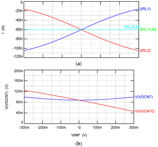
Figure 4.
(a) Currents IRL1, IRL2 in M1, M2 for complementary input signals Vi+ = VINP/2, Vi− = −VINP/2 and currents IRL1CM, IRL2CM in M1, M2 for common mode input signals Vi+ = Vi− = VINP; (b) control voltage VGcntl for differential complementary input signals and VGcntlCM for common mode input signals.
3. Transistor Level Implementation of FD-DDA
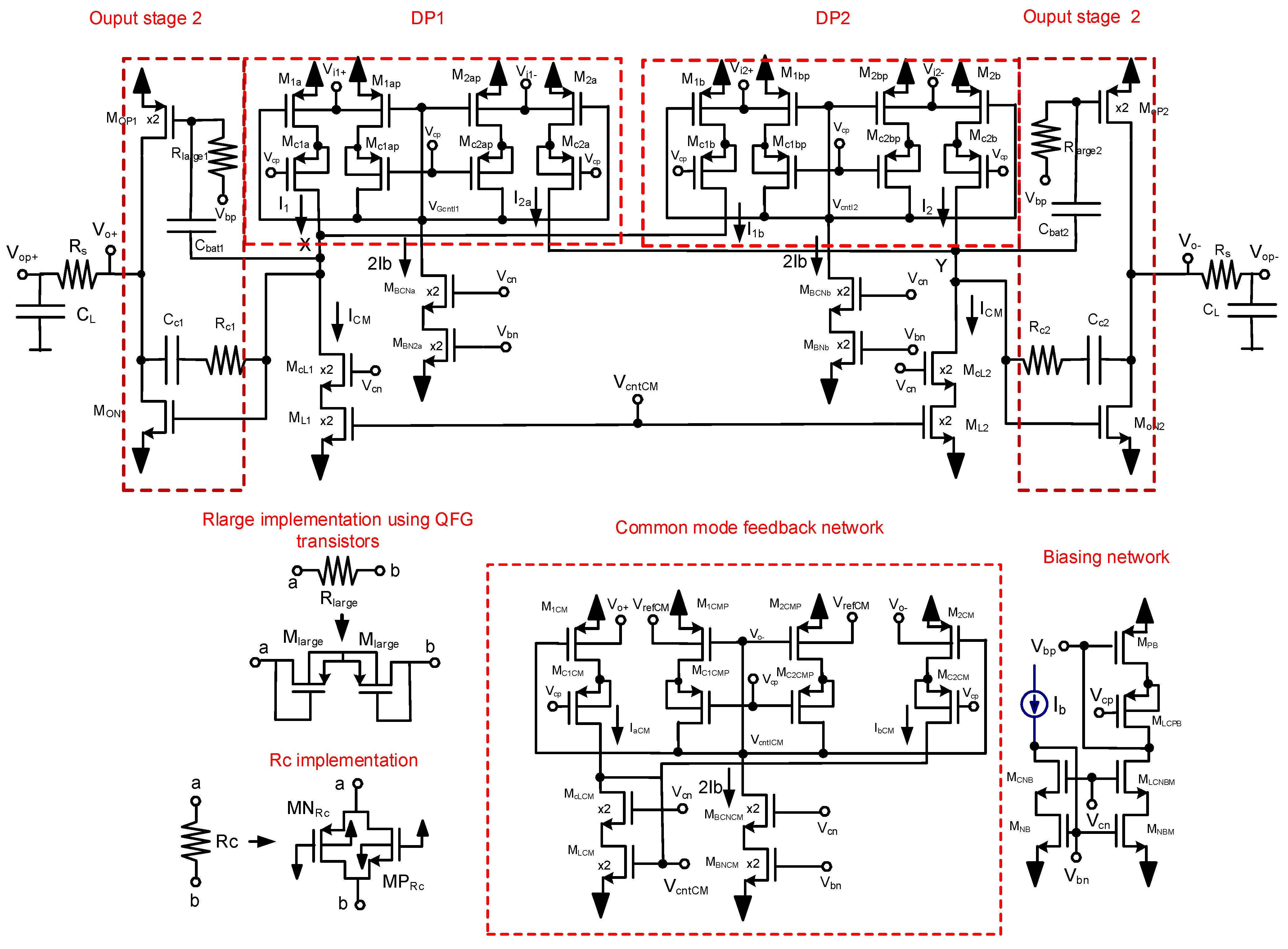
Figure 5 shows the full transistor level schematic of the FD-DDA with the architecture of Figure 2a. It is a two-stage Miller op-amp with a differential–difference input stage that uses two of the bulk-driven no-tail pseudo-DPs described in Section 2. The common-mode feedback network also uses a bulk-driven no-tail pseudo-DP cell. In the CMFB cell, the bulk terminals of transistors M1p and M2 are connected to the output reference common-mode voltage VrefCM, and the bulk terminals of M1 and M2p are connected to the FD-DDA output voltages Vo+ and Vo−. In this case, the cascoded load transistor MLCM is diode connected. The voltage VgntCM shows changes proportional to the difference between the common-mode output voltage VoCM = (Vo+ + Vo−)/2 and the output reference common-mode voltage VrefCM. It generates variations given by ΔVgcntCM = −K(VOcm − VrefCM) with K~1. The common mode feedback loop has approximately a gain ACM = (gmro)2. It operates with rail-to-rail output voltage variations. This differs from the conventional gate-driven two-differential pair-based CMFN that has a very limited common-mode operating range limited by the headroom of the gate-driven differential pairs HDDP used in its implementation. Conventional Rc − Cc Miller compensation elements are used. The output stages use the free class AB technique reported in [7] to achieve current efficient push–pull operation with output quiescent current IoutQ = Ib and dynamic peak output currents much larger than IoutQ. This is performed by transferring directly dynamic changes in nodes X and Y to the gates of the PMOS output transistors through capacitors Cbat that act as floating batteries. In practice, Rlarge and Cbat form a high-pass circuit with a very low 3 dB frequency (in the order of Hz). The large resistive elements Rlarge required in this technique are implemented using pseudo-resistors [7]. The input cascoded stage has a gain.
Ainp = gmbgmro2
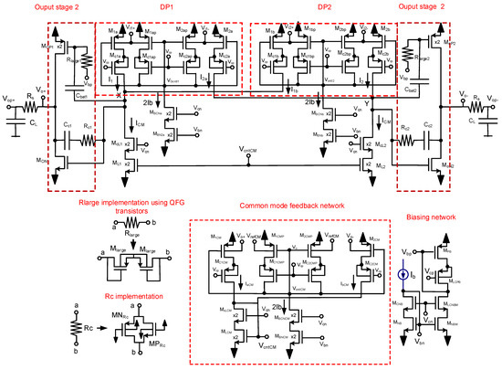
Figure 5.
Transistor level schematic of FD−DDA.
The output stage has a gain.
Aout = (gmoutP + gmoutN) roP||roN
The open-loop DC gain is given by Aol = AinpAout, the gain bandwidth product by
GB = (1/2π)(gmb/Cc)
The high frequency output pole is given by
fpoutHF = (1/2π)(gmoutP + gmoutN)/CL
The high frequency zero is given by
fzHF = (1/2π)(1/((1/(gmoutP + gmoutN) − Rc) Cc))
Resistor Rs is used for phase lead compensation to improve the phase margin of the FD-DDA. It generates a zero fzlead in the transfer function with a value.
fzlead = (1/2π)(1/RsCL)
4. Results
The buffer of Figure 1c using the FD-DDA circuit of Figure 5 was laid out and simulated in a commercial 180 nm CMOS technology using unit PMOS and NMOS transistor sizes W/L = 15 µm/0.4 μm. Ib = 60 nA. Some transistors are scaled by a factor two as shown by the “x2” in the schematic of Figure 5. Dual supply voltages VDD = 0.3 V, VSS = −0.3 V, CL = 50 pF, Rs = 10 kΩ, Cc = 0.5 pF and Rc = 10 MΩ were used. Rlarge resistors were implemented with two PMOS transistors in series with dimensions 2 µm/0.2 µm. Compensation resistors Rc were implemented as shown in Figure 5 with the parallel combination of a PMOS and an NMOS transistor with dimensions W = 0.5 µm/1 µm.
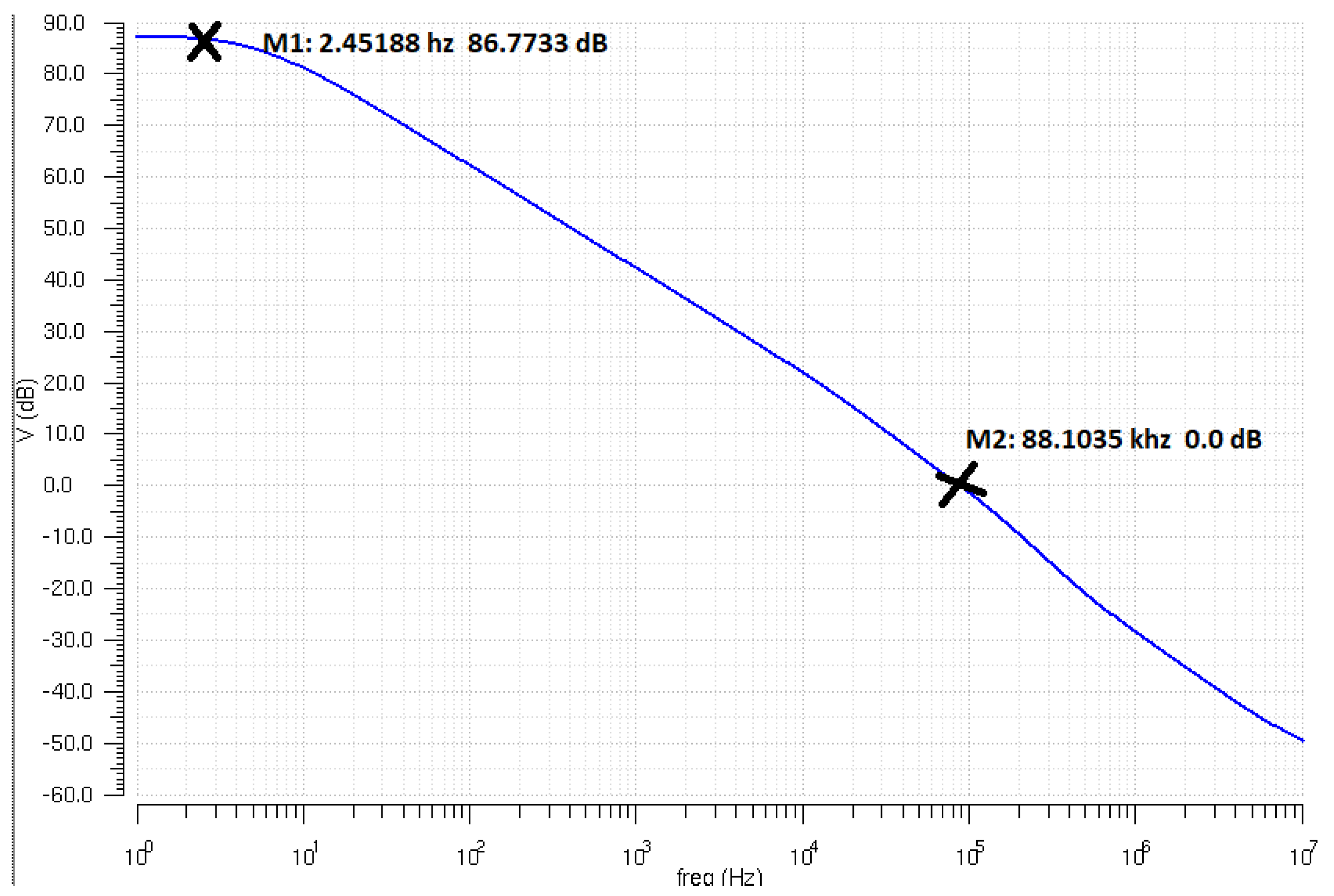
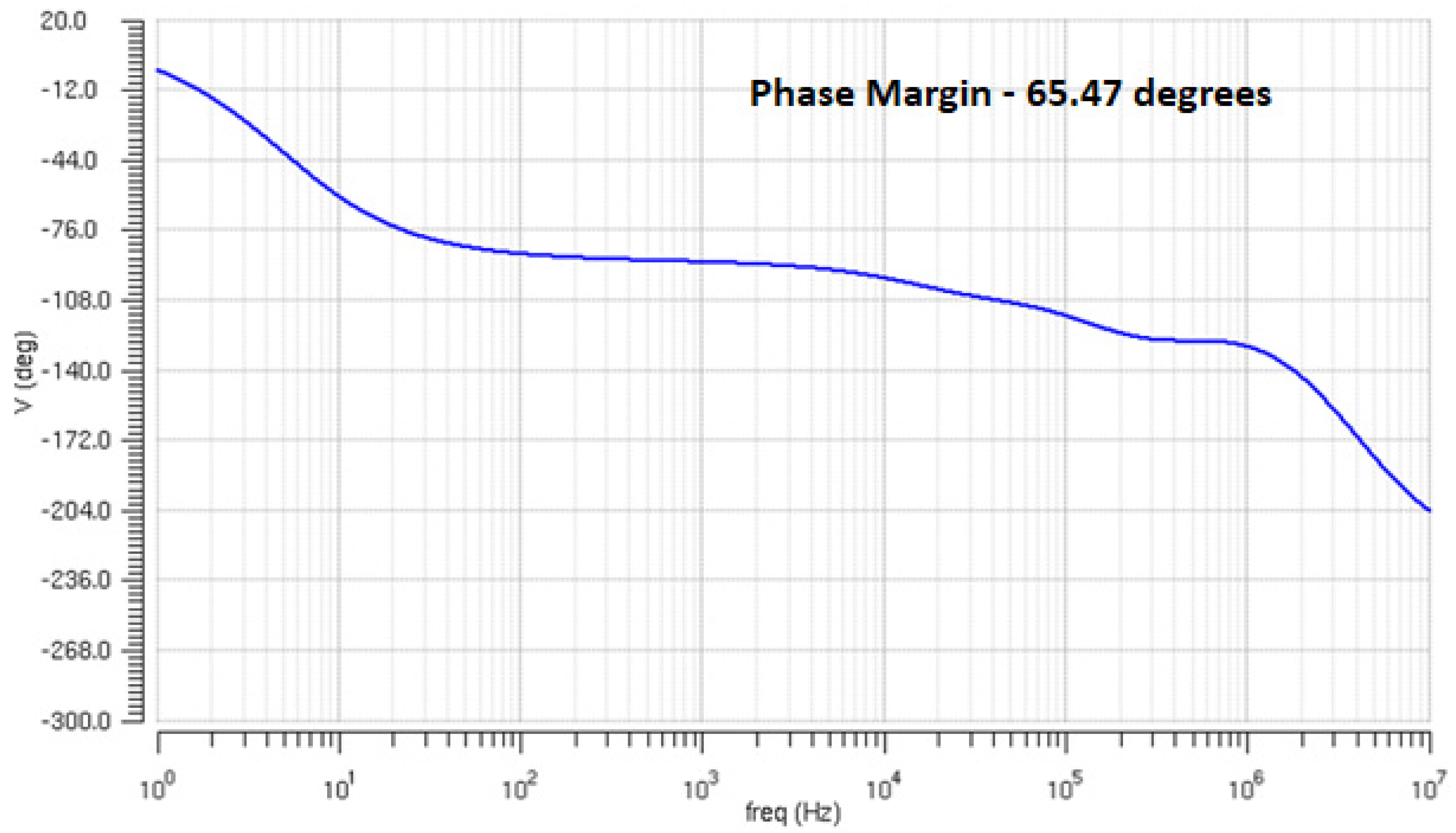
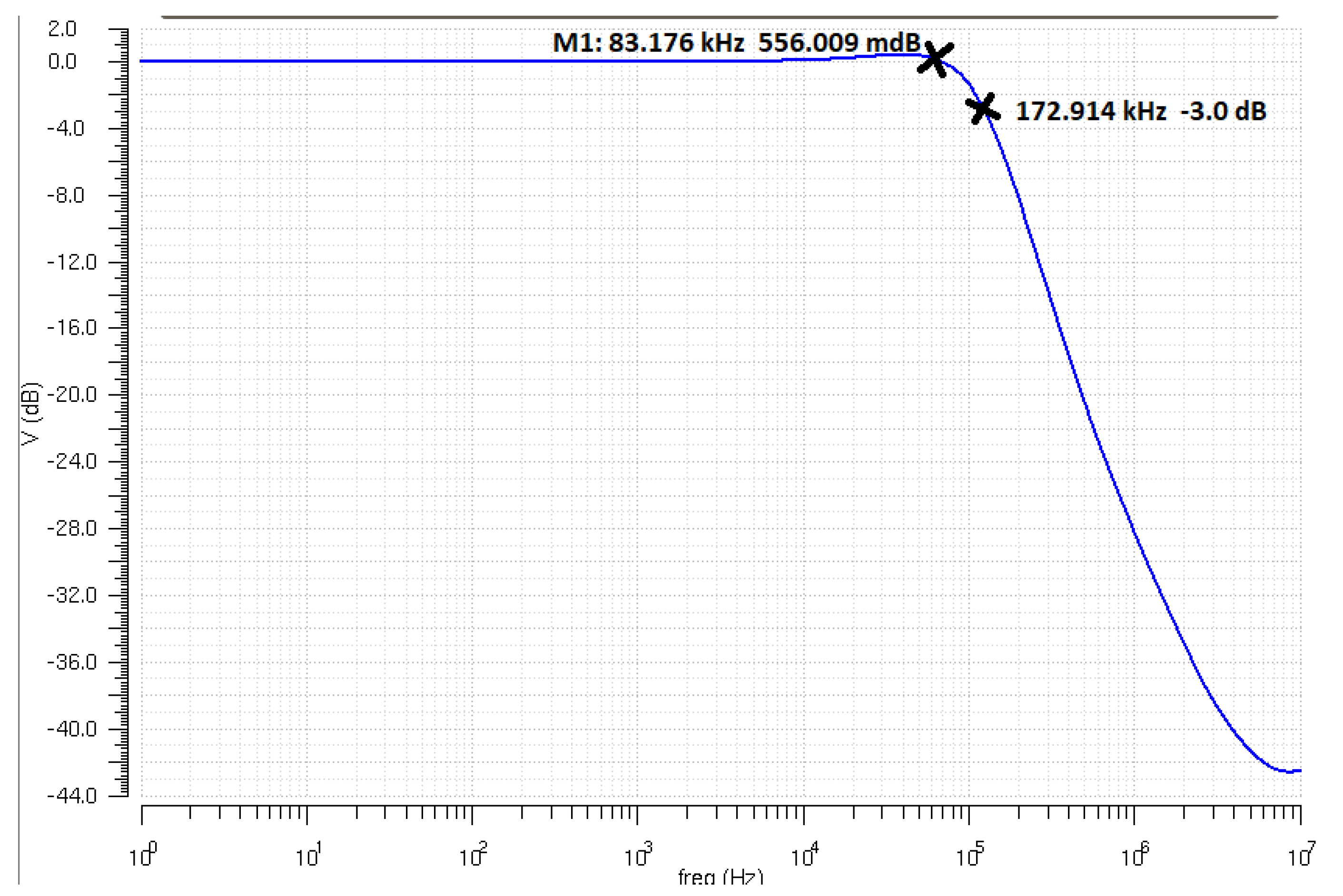
Figure 6 shows the layout of the FD-DDA with dimensions 45.5 × 135.2 µm2. Figure 7 shows the open-loop response of the FD-DDA It has a DC open-loop gain AolDC = 86.77 dB, a unity gain frequency fu = 88.1 kHz and a phase margin PM = 65.47°. Figure 8 shows the AC response of the buffer. It has a bandwidth BW = 172.91 kHz, with 0.556 dB peaking.

Figure 6.
Layout of FD-DDA.
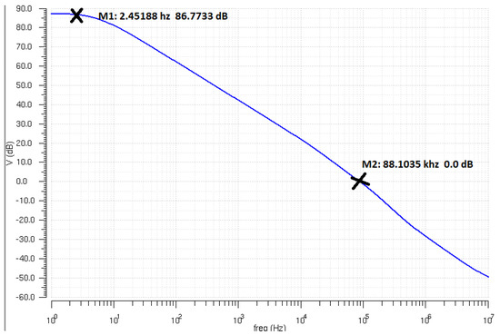
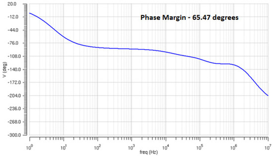
Figure 7.
Open-loop response of proposed bulk-driven FD-DDA.
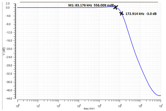
Figure 8.
AC response of proposed buffer.
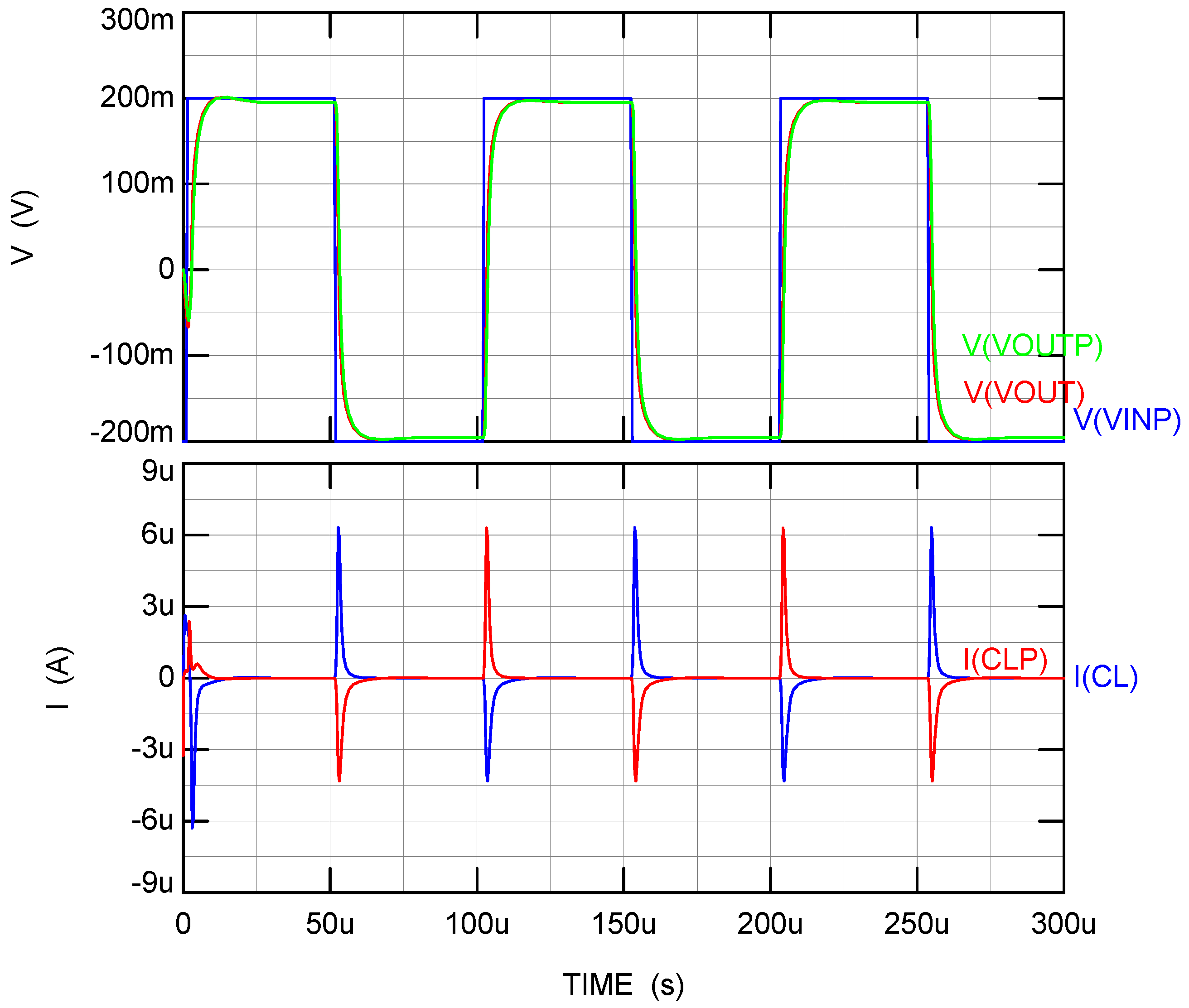
Figure 9 shows the transient response of the output waveforms Vout, Voutp and of the load capacitor currents ICL, ICLP to a 10 kHz, 0.4 VPP input pulse. It can be seen that the peak positive and negative currents have values Ipkpos = 6 µA and Ipkneg = −4.6 μA, and the buffer has a symmetrical slew rate SR+ = SR− = 0.238 V/µs. These currents are essentially larger than the output quiescent current IoutQ = 60 nA and than the total FD-DDA quiescent current ItotQ = 1.12 μA. A conventional class A DDA would have a peak negative output current of Ipk = IoutQ = 60 nA and would be characterized by an essentially lower slew rate of only SR− = 0.0012 V/µs.
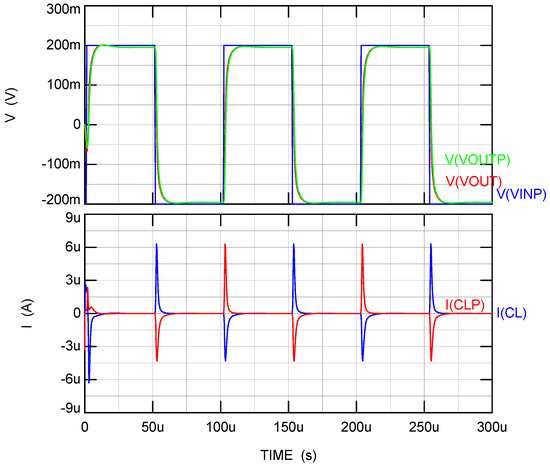
Figure 9.
Top: transient voltage response of Vout, Voutp to 10 kHz, 0.4 VPP input pulse Vinp; Bottom: transient load currents ICL, ICLP in load capacitors CL, CLP.
Other performance parameters obtained from simulations include: total quiescent power dissipation PtotQ = 0.666 μW, input noise spectral density at 1 kHz and RMS noise values 1.1 uV/√Hz and 0.34 mVRMS, respectively. RMS noise was obtained by integrating noise spectral density over the noise bandwidth. CMRR = 102 dB, PSRR+ = 109 dB, PSRR− = 100 dB, input DC offset voltage Vos = 3.5 mV. Vos was obtained including typical 2% transistor W/L mismatches. The small signal and large signal figures of merit of the proposed FD-DDA are FOMss = GBCLtot/PQ = 12.69 MHzpF/µW. FOMLS = SRCLtot/PQ = 34.79 (V/μs)pF/µW. The current efficiency is CE = Iouttotpk/ItotQ = 8.9. Total harmonic distortion is THD = 0.09% for a 10 kHz 0.2 VPP and 10 kHz sinusoidal input signal. Table 1, Table 2 and Table 3 show corner simulations of parameters at three temperatures spanning a 100 °C range.

Table 1.
Corner simulations at T = 90 °C.

Table 2.
Corner simulations at T = 27 °C.

Table 3.
Corner simulations at T = −10 °C.
Table 4 summarizes and compares the performance characteristics of the proposed op-amp and buffer to recently reported bulk-driven low-voltage circuits [11,12,13,14,15,16,17,18,19]. It can be seen that the proposed circuit has the highest small and large signal figures of merit.

Table 4.
Comparison table of proposed circuit to recently published bulk-driven op-amps.
5. Conclusions
A high performance true fully differential bulk-driven buffer operating from ±0.3V dual supply voltages is presented. A fully differential class AB Miller op-amp with differential–difference input stage is used to implement the buffer. A high CMRR no-tail bulk-driven cascoded pseudo-differential cell is used in the input stage and in the common mode feedback network of the op-amp. The circuit was verified with simulations in a commercial 180 nm CMOS technology.
Author Contributions
Conceptualization, M.G., J.R.-A., H.V.-L., J.H.-C., A.J.L.-M. and R.G.C.; methodology, M.G., J.R.-A., H.V.-L., J.H.-C., A.J.L.-M. and R.G.C.; software, M.G., J.R.-A., H.V.-L., J.H.-C., A.J.L.-M. and R.G.C.; validation, M.G., J.R.-A., H.V.-L., J.H.-C., A.J.L.-M. and R.G.C.; formal analysis, M.G., J.R.-A., H.V.-L., J.H.-C., A.J.L.-M. and R.G.C.; writing—original draft preparation, M.G., J.R.-A., H.V.-L., J.H.-C., A.J.L.-M. and R.G.C.; writing—review and editing, M.G., J.R.-A., H.V.-L., J.H.-C., A.J.L.-M. and R.G.C.; visualization, M.G., J.R.-A., H.V.-L., J.H.-C., A.J.L.-M. and R.G.C.; supervision, M.G., J.R.-A., H.V.-L., J.H.-C., A.J.L.-M. and R.G.C.; project administration, J.R.-A.; funding acquisition, A.J.L.-M. and R.G.C. All authors have read and agreed to the published version of the manuscript.
Funding
This research was partially funded by AEI/FEDER, grant number PID2019-107258RB-C31 and in part by the Andalusia Economy, Knowledge, Enterprise and University Council under Project P18-FR-4317.
Institutional Review Board Statement
Not applicable.
Informed Consent Statement
Not applicable.
Data Availability Statement
Not applicable.
Conflicts of Interest
The authors declare no conflict of interest.
References
- Casson, A.J.; Logesparan, L.; Rodriguez-Villegas, E. An introduction to future truly wearable medical devices—ASIC. In Proceedings of the 2010 Annual International Conference of the IEEE Engineering in Medicine and Biology, Buenos Aires, Argentina, 31 August–4 September 2010; Volume 30, pp. 3430–3431. [Google Scholar]
- Chatterjee, S.; Tsividis, Y.; Kinget, P. 0.5-V analog circuit techniques and their application in OTA and filter design. IEEE J. Solid-State Circuits 2005, 40, 2373–2387. [Google Scholar] [CrossRef]
- Stopjakova, V.; Rakus, M.; Kovac, M.; Arbet, D.; Nagy, L.; Sovcik, M.; Potocny, M. Ultra-Low Voltage Analog IC Design: Challenges, Methods and Examples. Radioengineering 2018, 27, 171–185. [Google Scholar] [CrossRef]
- Ramirez-Angulo, J.; Ledesma, F. The universal op-amp and applications in continuous-time resistorless and capacitorless linear weighted voltage addition. IEEE Trans. Circuits Syst. II Express Briefs 2006, 53, 404–408. [Google Scholar] [CrossRef]
- Sackinger, E.; Guggenbuhl, W. A versatile building block: The CMOS differential difference amplifier. IEEE J. Solid-State Circuits 1987, 22, 287–294. [Google Scholar] [CrossRef]
- Huang, S.-C.; Ismail, M. A wide range differential difference amplifier: A basic block for analog signal processing in MOS technology. IEEE Trans. Circuits Syst. II 1993, 40, 289–301. [Google Scholar] [CrossRef]
- Ramirez-Angulo, J.; Carvajal, R.G.; Galan, J.A.; Lopez-Martin, A. A free but efficient low-voltage class-AB two-stage operational amplifier. IEEE Trans. Circuits Syst. II Express Briefs 2006, 53, 568–571. [Google Scholar] [CrossRef]
- Grech, I.; Micallef, J.; Azzopardi, G.; Debono, C.J. A low voltage wide-input range bulk-input CMOS OTA. Analog. Integr. Circuits Signal Process. 2005, 43, 127–136. [Google Scholar] [CrossRef]
- Trakimas, M.; Sonkusale, S. A 0.5 V bulk-input OTA with improved common-mode feedback for low-frequency filtering applications. Analog. Integr. Circuits Signal Process. 2009, 59, 83–89. [Google Scholar] [CrossRef]
- Abdelfattah, O.; Roberts, G.W.; Shih, I.; Shih, Y.S. An Ultra-Low-Voltage CMOS Process-Insensitive Self-Biased OTA With Rail-to-Rail Input Range. IEEE Trans. Circuits Syst. I Regul. Pap. 2015, 63, 2380–2390. [Google Scholar] [CrossRef]
- Cabrera-Bernal, E.; Pennisi, S.; Grasso, A.D.; Torralba, A.; Carvajal, R.G. 0.7-V Three-Stage Class-AB CMOS Operational Transconductance Amplifier. IEEE Trans. Circuits Syst. I Regular Papers 2016, 63, 1807–1815. [Google Scholar] [CrossRef]
- Zuo, L.; Islam, S.K. Low-Voltage Bulk-Driven Operational Amplifier with Improved Transconductance. IEEE Trans. Circuits Syst. I 2013, 60, 2084–2091. [Google Scholar] [CrossRef]
- Kulej, T.; Khateb, F. 0.4-V bulk-driven differential-difference amplifier. Microelectron. J. 2015, 46, 362–369. [Google Scholar] [CrossRef]
- Qin, Z.; Tanaka, A.; Takaya, N.; Yoshizawa, H. 0.5-V 70-nW Rail-to-Rail Operational Amplifier Using a Cross-Coupled Output Stage. IEEE Trans. Circuits Syst. II 2016, 63, 1009–1013. [Google Scholar] [CrossRef]
- Khateb, F.; Kulej, T. Design and Implementation of a 0.3-V Differential Difference Amplifier. IEEE Trans. Circuits Syst. I 2019, 66, 513–523. [Google Scholar]
- Kulej, T.; Khateb, F.A. Compact 0.3-V Class AB Bulk-Driven OTA. IEEE Trans. VLSI Syst. 2020, 28, 224–232. [Google Scholar] [CrossRef]
- Woo, K.C.; Yang, B.D. A 0.25-V Rail-to-Rail Three-Stage OTA With an Enhanced DC Gain. IEEE Trans. Circuits Syst. II 2020, 67, 1179–1183. [Google Scholar] [CrossRef]
- Khateb, F.; Kulej, T.; Kumngern, M.; Arbet, D.; Jaikla, W. A 0.5-V 95-dB rail-to-rail DDA for biosignal processing. AEU—Int. J. Electron. Commun. 2022, 145, 154098. [Google Scholar] [CrossRef]
- Kulej, T.; Khateb, F.; Arbet, D.; Stopjakova, V. A 0.3-V High Linear Rail-to-Rail Bulk-Driven OTA in 0.13 μm CMOS. IEEE Trans. Circuits Syst. II Express Briefs 2022, 69, 2046–2050. [Google Scholar] [CrossRef]
- Tang, N.; Hong, W.; Kim, J.H.; Yang, D.; Heo, D. A Sub-1-V Bulk-Driven Opamp With an Effective Transconductance-Stabilizing Technique. IEEE Trans. Circuits Syst. II Express Briefs 2015, 62, 1018–1022. [Google Scholar] [CrossRef]
- Akbari, M.; Hussein, S.; Hashim, Y.; Tang, K.T. An Enhanced Input Differential Pair for Low-Voltage Bulk-Driven Amplifiers. IEEE Trans. VLSI Syst. 2021, 29, 1601–1611. [Google Scholar] [CrossRef]
- Baghtash, H.F. A 0.4 V, body-driven, fully differential, tail-less OTA based on current push-pull. Microelectron. J. 2020, 99, 104768. [Google Scholar] [CrossRef]
- Veldandi, H.; Shaik, R.A. A 0.3-v pseudo-differential bulk-input ota for low-frequency applications. Circuits Syst. Signal Process. 2018, 37, 5199–5221. [Google Scholar] [CrossRef]
Publisher’s Note: MDPI stays neutral with regard to jurisdictional claims in published maps and institutional affiliations. |
© 2022 by the authors. Licensee MDPI, Basel, Switzerland. This article is an open access article distributed under the terms and conditions of the Creative Commons Attribution (CC BY) license (https://creativecommons.org/licenses/by/4.0/).

