Article

A Morphable Physically Unclonable Function and True Random Number Generator Using a Commercial Magnetic Memory

by
Mohammad Nasim Imtiaz Khan
1,*,
Chak Yuen Cheng
1,2,
Sung Hao Lin
1,
Abdullah Ash-Saki
1 and
Swaroop Ghosh
1
1
Department of Electrical Engineering, Pennsylvania State University, State College, PA 16801, USA
2
Department of Electrical and Computer Engineering, Carnegie Mellon University, Pittsburgh, PA 15213, USA
*
Author to whom correspondence should be addressed.
J. Low Power Electron. Appl. 2021, 11(1), 5; https://doi.org/10.3390/jlpea11010005
Submission received: 23 December 2020 / Revised: 11 January 2021 / Accepted: 11 January 2021 / Published: 14 January 2021
(This article belongs to the Special Issue Low Power Memory/Memristor Devices and Systems)

Abstract

:
We use commercial magnetic memory to realize morphable security primitives, a Physically Unclonable Function (PUF) and a True Random Number Generator (TRNG). The PUF realized by manipulating the write time and the TRNG is realized by tweaking the number of write pulses. Our analysis indicates that more than 75% bits in the PUF are unusable without any correction due to their inability to exhibit any randomness. We exploit temporal randomness of working columns to fix the unusable columns and write latency to fix the unusable rows during the enrollment. The intra-HD, inter-HD, energy, bandwidth and area of the proposed PUF are found to be 0, 46.25%, 0.14 pJ/bit, 0.34 Gbit/s and 0.385 μm2/bit (including peripherals) respectively. The proposed TRNG provides all possible outcomes with a standard deviation of 0.0062, correlation coefficient of 0.05 and an entropy of 0.95. The energy, bandwidth and area of the proposed TRNG is found to be 0.41 pJ/bit, 0.12 Gbit/s and 0.769 μm2/bit (including peripherals). The performance of the proposed TRNG has also been tested with NIST test suite. The proposed designs are compared with other magnetic PUFs and TRNGs from other literature.

1. Introduction

There has been a proliferation of Internet-of-Things (IoTs) edge devices, and cybersecurity aspects of such devices are becoming a concern. Cybersecurity techniques, securing only the upper layer of software stack, are not sufficient anymore as underlying hardware faces a plethora of security and trust issues such as cloning, reverse engineering, Trojan insertion, side channel attack [1], recycling/counterfeiting, and so on. Therefore, many techniques and countermeasures are explored to ensure security and trust of hardware systems at various levels. For example, security primitives like recycling sensor [2], Physically Unclonable Functions (PUF) [3,4], True Random Number Generator (TRNG) [5], tamper sensor [6], encryption engines [7], Trojan detection [8,9,10], etc., are proposed to secure hardware. The security solutions are mostly driven by CMOS -based technologies. However, the CMOS-based solutions can be limited by the small set of features that can be leveraged to develop security primitives such as process-variation (PV) and thermal noise. In this regard, emerging technologies can be promising. They offer new sources of randomness and noise that can be harnessed to design robust security primitives. Besides, the solutions can achieve low power, high density, and high speed.
Prior Work on PUF: PUF is one of the widely accepted hardware security primitives that finds application in authentication. A PUF exploits differences between two chips due to intrinsic variation during the manufacturing process [4] to generate chip-specific and unique signatures. Several conventional and emerging technologies such as CMOS [3,4], memristor [11] and spintronic technologies [12,13] are explored to design PUFs. The CMOS PUFs include Static RAM (SRAM) based memory PUF, arbiter PUF and ring oscillator based PUFs [3]. Emerging technology based PUFs include memristor, spintronic memory, Resistive RAM (RRAM) [14,15], Domain Wall Memory (DWM), Magnetoresistive RAM (MRAM), etc. For example, DWM is used to design arbiter PUFs with exponential Challenge Response Pairs (CRP) which are resilient to machine learning attack [16]. Several PUFs based on Magnetoresistive RAM (MRAM) are also proposed [17,18,19]. In [17], the authors utilize unique energy-tilt of a Magnetic Tunnel Junction (MTJ) which stems from random geometric variations in the MRAM cells to generate PUF responses. The work in [18] identified the unreliable cells in a PUF to devise a zero bit-error-rate PUF. In Ref. [19], a strong PUF is proposed based on combining the resistances of a group of cells and generating their digital signature. The work exploits nano-scale analog disorders of MRAM, and this technique can be extended to other memory technologies.
Prior Work on TRNG: TRNGs exploit a source of randomness such as thermal noise, dynamic variations, etc. to generate random numbers. Ideally, the outputs of a TRNG must have high entropy and zero correlation. Several TRNGs are proposed using spintronic devices in prior work [20,21,22,23]. In [20,21], TRNG is implemented by manipulating the amplitude of the programming pulse. However, Ref. [20] requires controlling current in the order of μAs which is hard to achieve and Ref. [21] requires integration of analog circuit which is very sensitive to noise. A stochastic programming by current-driven STT using a Complementary Polarizer Spin Dice (CPSD) proposed in [22]. In [23], algorithms for PUF (based on read current) and TRNG (based on pulse width/amplitude manipulation) are proposed using MRAM. However, implementation details and results are not provided.
Proposed morphable PUF and TRNG: We propose a morphable security primitive using commercial magnetic RAM which can be used as both a PUF and a TRNG. To run it in the PUF mode, write time is controlled, and to run it in the TRNG mode, the number of write pulses is manipulated. Thus, it is named as morphable.
The magnetic tunnel junctions (MTJs) in the MRAM exhibit different write latencies owing to intrinsic and extrinsic PVs. For the same write time a bit may (or may not) flip in two different chips (extrinsic variation). This observation can be exploited to generate unique signatures from different chips which is useful for designing a PUF. We also notice that the same bit in a chip will randomly flip (intrinsic variation) if written multiple times with the same data. This is useful for designing a TRNG. The Figure 1 schematically shows the concept of re-purposing the MRAM in two different modes, i.e., PUF and TRNG. Thus, a 128 KB commercial MRAM chip can be converted to work solely as a 128 KB PUF or a 128 KB TRNG, or it can cohabitate a 64 KB PUF and a 64 KB TRNG.
Note that the data width of the MRAM chips we used for this work is 8-bit. Therefore, we call each address as a row and number the rows with the corresponding address. Each row produces 8 bit and we number them as column 0 to 7 from Most Significant Bit (MSB) to Least Significant Bit (LSB). We summarize our methodology to realize PUF and TRNG from the MRAM chip below.
Working principle of proposed PUF (wPUF): First, we flush the bits of the PUF (write with 0s). Then, we try writing 1 in all the bits. The write time of the pulse is set to 50% switching probability so that 50% of the bits flip. However, due to stochastic nature of the bitcell and process variation, each chip will be written with different data which can be used as the signature of the chip. However, our analysis shows that 4 columns of all rows of the chips are stuck to 0 (2 columns)/1 (2 columns) and do not show probabilistic switching as expected. Remaining 4 columns show the probabilistic switching and therefore, overall switching probability is around 50%. These severely limits PUF variation from chip to chip. We noted that the 4 columns are stuck because either they are very strong (stuck to 0, requires more write time) or weak (stuck to 1, requires less write time and always gets written to 1). We expect that the PUFs based on real memory chip implementation of any emerging NVMs might exhibit this type of behavior. Therefore, some of the bits of each address could be unusable for PUF. In this work, we propose techniques to fix these bad columns by exploiting the temporal randomness of good columns. Note that this is in contrast to MRAM and STT-MRAM PUFs presented in literature [17,18,19] that are specifically and carefully designed (bits, access transistor and peripherals) to amplify and capture the variability and to achieve high inter-HD and low intra-HD.
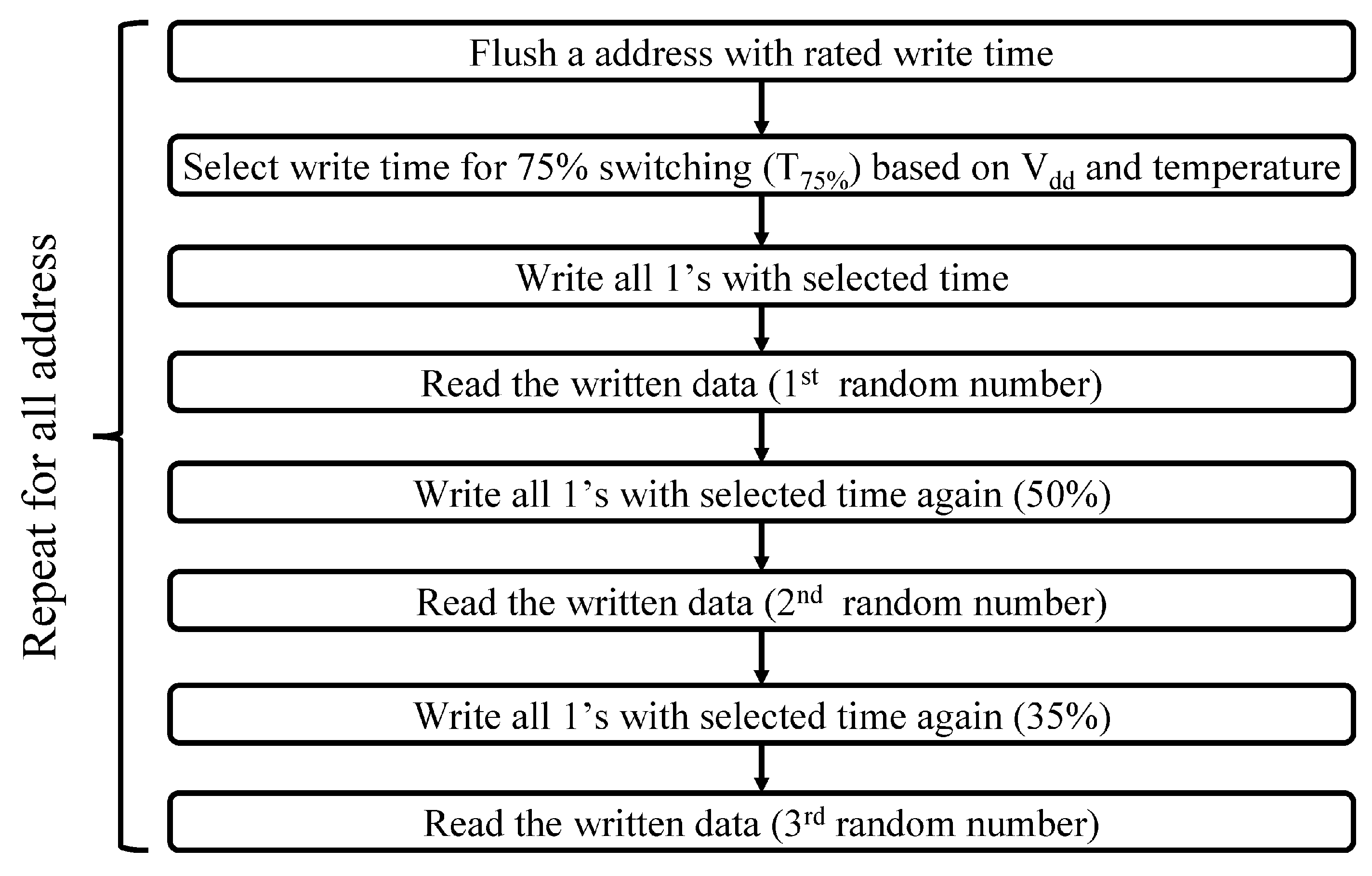
Working principle of proposed TRNG: Our analysis show that just biasing an address with 50% switching probability does not provide all possible outcomes. For example, the number of possible outcomes for a 4-bit TRNG is 16. However, we observed less number of outcomes due to strong/weak bits which limits the scope of the TRNG and makes it Pseudo Random Number Generator (PRNG). Therefore, we propose the following technique for TRNG: first, we write all 0 s in the cells of TRNG; then we write all bits to 1 s by selecting the write time to flip 75% of the bits (i.e., 75% switching probability) to extract the first random number. For generating the second and third random number from the same address, we propose to repeat the above steps with the write time to flip 50% of the bits (i.e., 50% switching probability) and with the write time to flip 25% of the bits (i.e., 25% switching probability) respectively. This way we get all 16 possible outcomes from the 4 good columns with tolerable standard deviation. For example, 75% switching probability will mainly generate 4’b0111, 4’b1011, 4’b1101 and 4’b1110, 50% will mainly generate 4’b0011, 4’b0101, 4’b1001, 4’b0110, 4’b1010 and 4’b1100 and 25% will mainly generate 4’b0001, 4’b0010, 4’b0100 and 4’b1000. The remaining ones (4’b0000/4’b1111) are also generated (with lower recurrence number) mainly with 25%/75% probability if all the four bits are either very strong or weak respectively. Note that we did not fix the 4 bad columns with the good ones in case of TRNG. This is to prevent machine learning attacks that can profile the TRNG outcomes with fewer iterations (since the fixing can make the bits correlated).
Morphable Security Primitive: To use the MRAM in the TRNG mode (i.e., to generate unique true random numbers), the MRAM needs to be re-written every time. On the other hand, to use it as a PUF, the MRAM needs to be written only once (during the enrollment phase). The data that get written to PUF addresses depends on the PV which cannot be replicated by a malicious entity. It should be noted that PUF can be morphed to TRNG if written multiple times as proposed for TRNG.
To the best of our knowledge, this is the first experimental demonstration of a PUF and TRNG using commercial MRAM chip. A work-in-progress version of this work has been published in [24] where the methodology is discussed and initial data were presented. However, this work explains the design and results in detail. In summary, we make the following contributions:
  • We characterize the MRAM bit-to-bit write latency under voltage and temperature variations.
  • We characterize the MRAM response under multiple write disturbs which can be useful for TRNG.
  • We propose a write PUF (wPUF) by biasing the MRAM with a write latency with 50% switching probability. The proposed PUF exhibits excellent stability and uniqueness.
  • We show that 75% of the bits could be unresponsive to a challenge and propose techniques to convert them into useful bits avoiding expensive row and columns masking.
  • We propose a TRNG by exploiting random MRAM responses under multiple write disturbs.
  • We benchmark the proposed PUF and TRNG with existing designs.
The rest of the paper is organized as follows: Section 2 provides the background of MRAM technology, details of the experimental setup and analysis of the MRAM responses to write latency and number of writes. Section 3 and Section 4 describe the proposed PUF and TRNG. Section 5 presents discussion and Section 6 draws conclusions.

2. Background on MRAM and Its Variation

In this section, we present basics of the toggle MRAM and characterize its statistical and temporal behavior.

2.1. Basics of MRAM

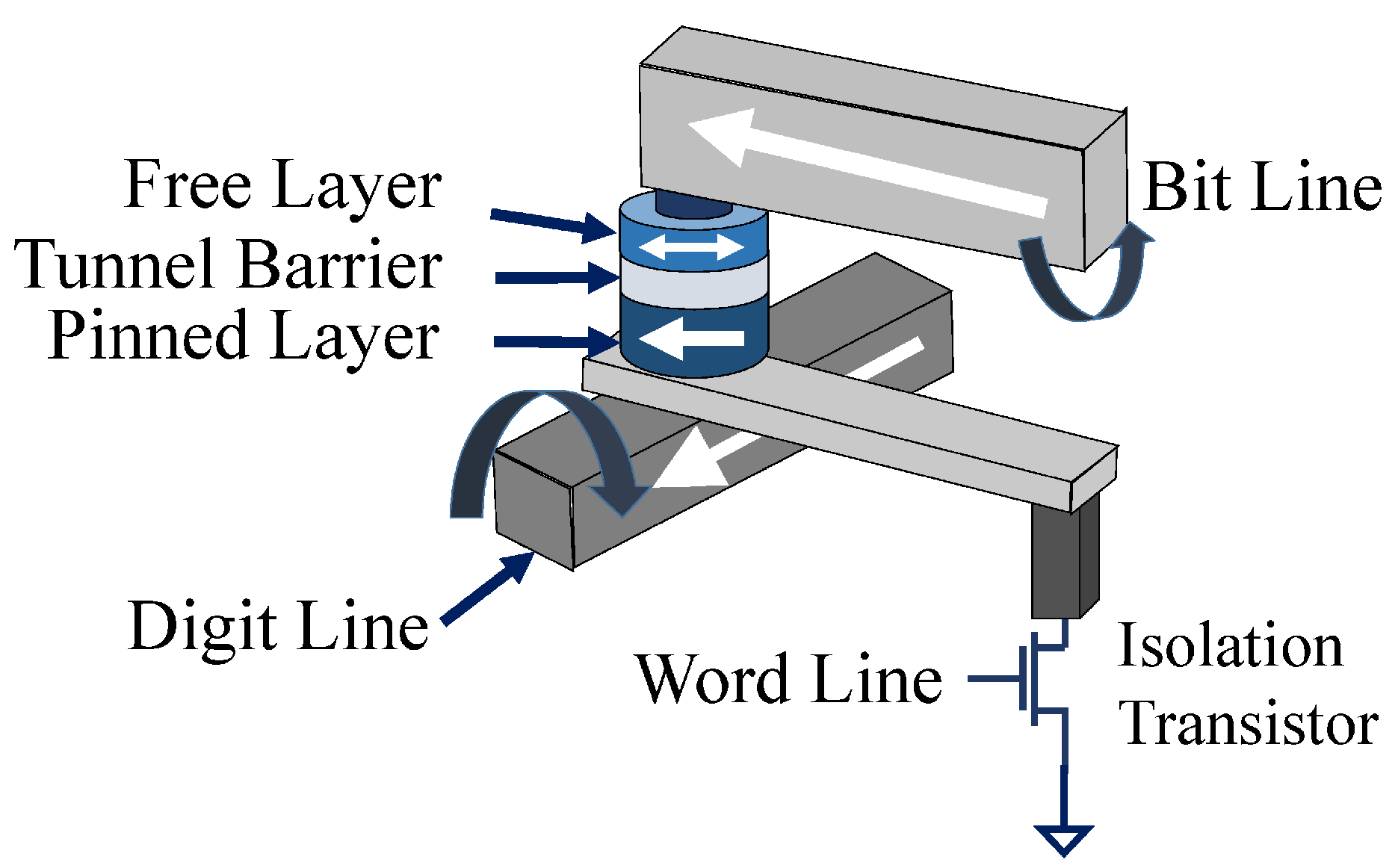
MRAM bitcell (Figure 2) contains one MTJ and one NMOS access transistor. The MTJ lies between a pair of metal-lines named digit-line and bit-line to facilitate write operation. The metal-lines are parallel to the cell plane and placed orthogonal to each other. An induced magnetic field is created with appropriate polarity by passing current through the lines during write operation. The field exerts a torque on the free layer magnetic orientation, causing it to flip. During read operation, the access transistor is turned ON, and a fixed voltage is applied across the cell to sense the equivalent resistance.
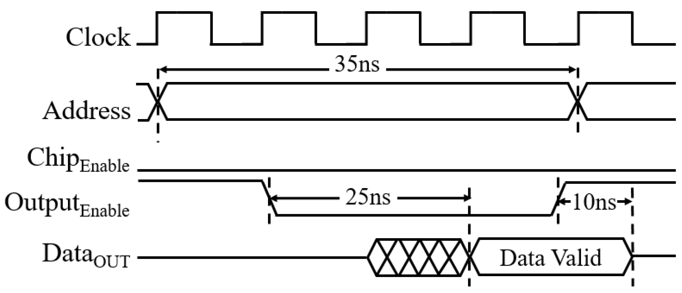
A commercial toggle MRAM chip (MR4A08B) with 2 million rows and 8 columns is used in this work to validate the proposed morphable security primitive. Table 1 captures the key features of the MRAM chip. It should be noted that we have used the first 128 KB (1 Mbit) out of 16 Mbit of the chip. Figure 3 and Figure 4 presents the timing diagram of the write and read operations of the MRAM chip. From the data sheet, it is evident that the chip requires maximum of 15 ns of write enable (low) signal for successful write and data is valid after 25 ns of read enable signal. In this work, we modified the specified read and write times to realize the proposed PUF and TRNG.

2.2. Experimental Setup

A four-layer PCB is designed to interface the MRAM chip with a logic analyzer and Digilent Basys3 [25]. The PCB is designed with minimum wire resistance, inductance and capacitance to stabilize the supply current for PUF power measurement. A 1 Ω thick film current sensing resistor is connected between the ground of the PCB and the MRAM chip to sense the MRAM current during read/write. A heat gun is used to change the ambient temperature. We have analyzed a total of 10 chips.
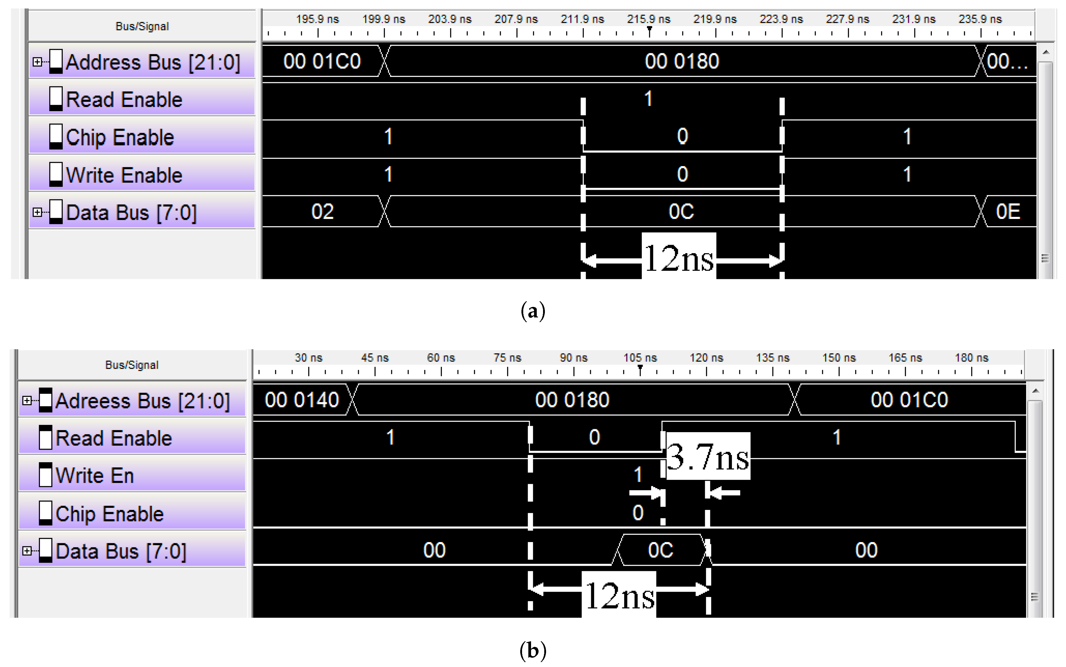
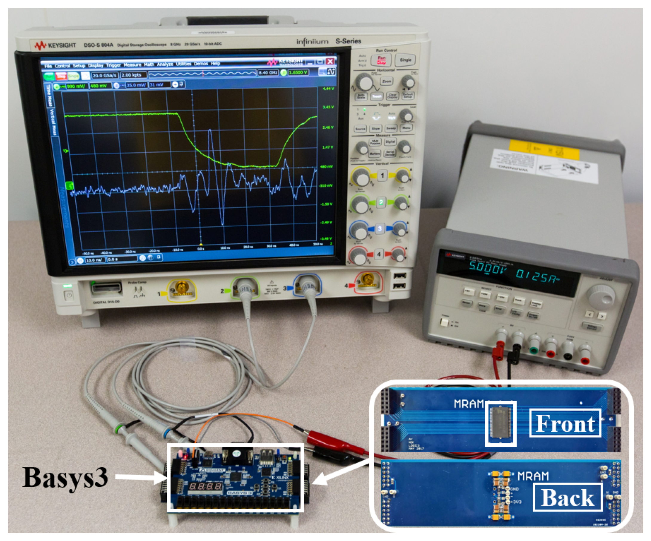
First, we interfaced the MRAM chip with logic analyzer and wrote all addresses at faster than 15 ns write time@ V D D = 3.3 V, 25 °C. We found that the data is written successfully for all chips at 12 ns (Figure 5). Therefore, the write time should be less than 12 ns at nominal operating condition to bias the cells with 50% write probability. We read the data at 30 ns in order to avoid read failures. Next, we interfaced the MRAM chip with the FPGA. The writing is done at much higher frequency to achieve partial write and reading is done at 25 MHz (40 ns). The read/write traces are captured by Keysight DSOS-804A Oscilloscope [26] with sampling frequency of 20 GSa/s and Bandwidth of 8 GHz. The experimental setup is shown in Figure 6. Data is sent to a PC using UART (baud rate 9600 bps) for MATLAB analysis.

2.3. Switching Variation of MRAM

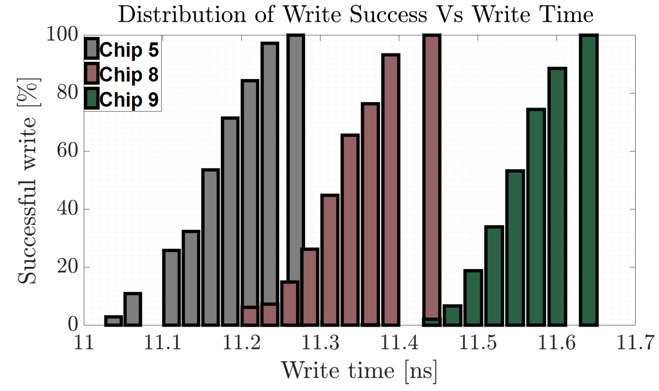
We swept the write time of each of the 10 chips to identify the Cumulative Distribution Function (CDF) of write time for 0 1 switching. Figure 7 shows the CDFs of three chips that are found to possess highest/median/lowest write times. To realize PUF, the write latency of each chip should be chosen to write 50% of the bits to get uniform 0/1 distribution. From Figure 7 it is obvious that write time varies from chip to chip. This could be useful for TRNG application. From the experimental results and analysis, we note the following:
(a) The write latency can be arranged in increasing order as, 0 0 , 1 0 , 0 1 , 1 1 (i.e., writing 0 0 takes shortest time and 1 1 takes longest time ( T ( 1 1 ) )).
(b) For writing 1 1 with t w r i t e < 10 ns and 10 ns < t w r i t e < T 1 1 , the stored data becomes 0 and stochastic respectively. From this observation we conclude that the chip initializes the data to 0 before writing a 0 or 1. We believe that, this observation is rooted at the toggle MRAM implementation which toggles the bit (irrespective of the existing state) during write.
(c) Consecutive writes of 1 s with the same short write time reduces number of 1 s in the data (consequence of (b)). For example, if the addresses are flushed with all 0 s and then written with all 1 s with write time to flip 75% bits (which is < T 1 1 ) and the writing is repeated with same time (without flushing in between), the number of 1 s in the data reduces to ≈49%, ≈34% and then remains fairly constant (Figure 8). This can be useful for TRNG (further explained in Section 4).
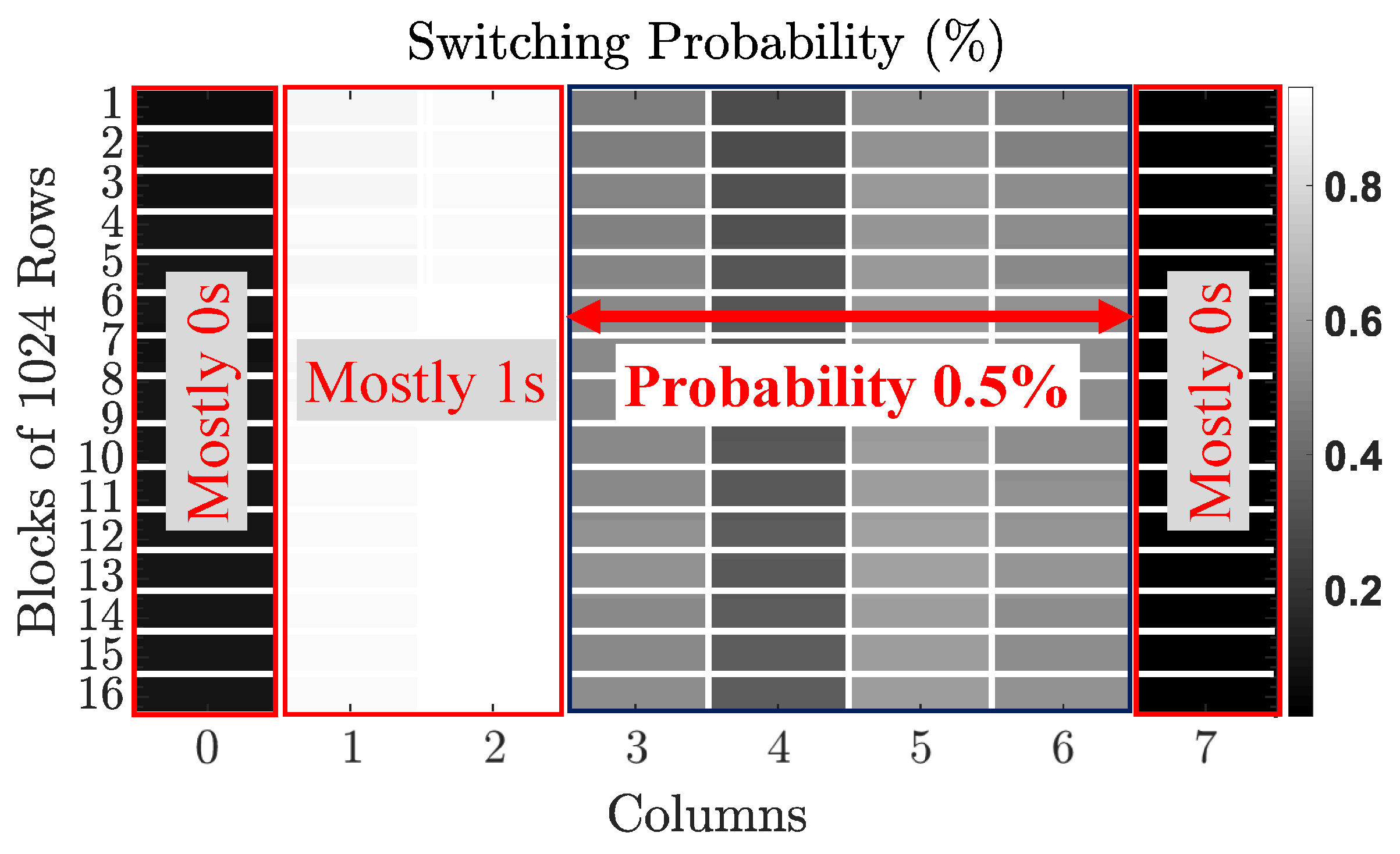
(d) Columns 0 and 7 are biased to data 0, columns 1 and 2 are biased to data 1 and column 3–6 mainly shows 50% switching probability (Figure 9) although we select the write time to flip 50% of the bits for the entire memory array. Therefore, columns 0, 1, 2 and 7 cannot be used for PUF and TRNG. If every cell needs to be biased at their own 50% switching probability, then write time for each cell in a row/column needs to be controlled individually which is practically impossible.
(e) Error-free read can be performed with 23.3 ns under 3.0 V–3.6 V and 25 C–60 C. The highest read latency is 23.3 [email protected] V, 60 C and lowest read latency is 22.47 [email protected] V, 25 C.

3. PUF

Memory PUFs exploit random initialization of the memory bits due to PV. The address bits are used as challenge and the bits read from the memory array with the address is the response of the PUF. In this section, we present the proposed wPUF and analyze its performance using experimental results.

3.1. Proposed wPUF

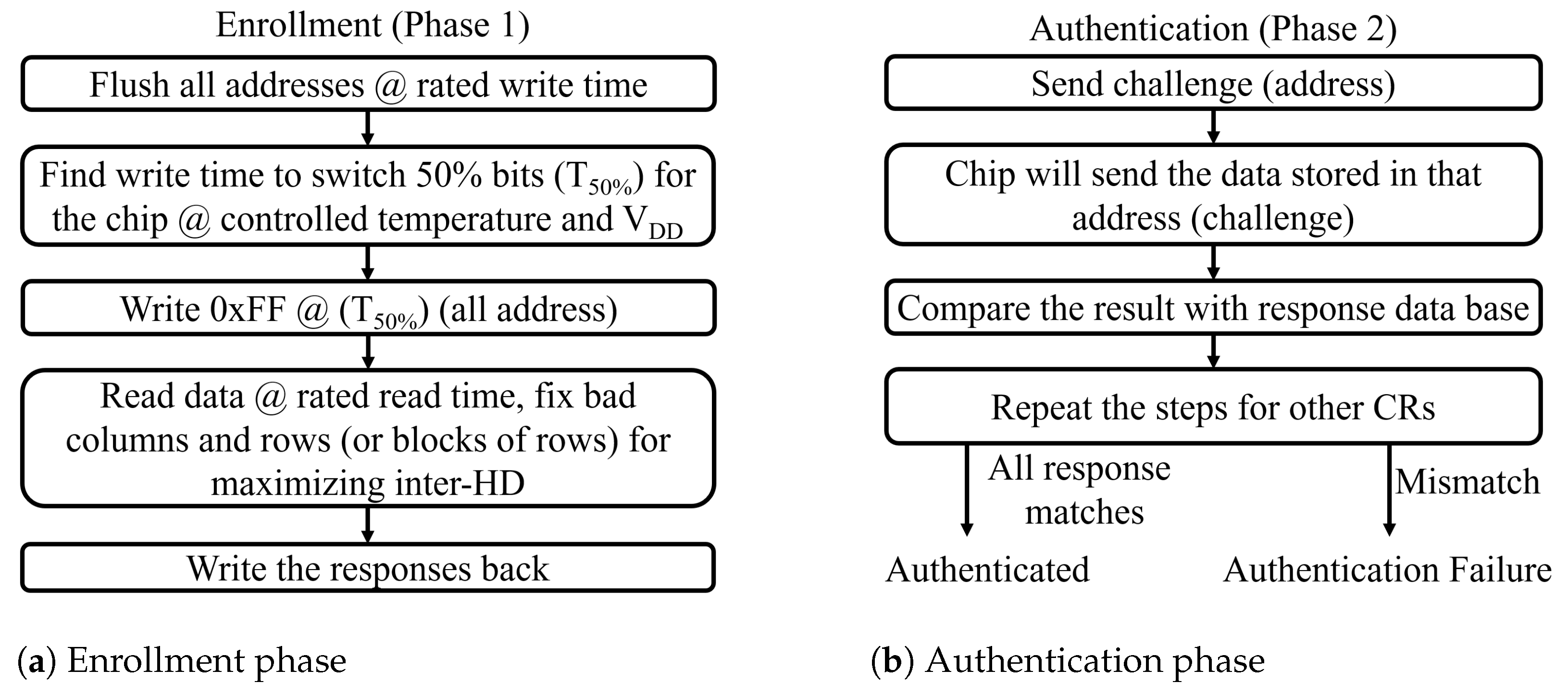
The principle of the proposed wPUF is explained in algorithm (Figure 10). The wPUF will have two phases:
(a) Enrollment phase (Figure 10a): In this phase, unique signature from a chip is extracted using the method described below. First, the manufacturer prepares the memory in an initial state by writing all bits with 0 s (flushing of the MRAM). Next, the manufacturer try writing all 1 s with a write time T 50 % to switch 50% bits to 1. Note that, T 50 % is supply voltage ( V D D ) and temperature dependent. As the manufacturer has access to a controlled-environment, managing target V D D and temperature will not be an issue. Finally, the entire address space is read to extract unique signatures. The steps are repeated for several chips to create a pool of data for statistical analysis and subsequent correctional measures. Then, all chip responses will be compared to separate the unresponsive columns/rows (that show no variation) for all chips and which gives highest uniqueness for different chips. Based on this observation, the unresponsive columns and rows need further processing (discussed in Section 3.3).
(b) Authentication phase (Figure 10b): This phase involves sending challenges (memory addresses) to the PUF and getting back responses (data stored in those addresses). Sufficient number of CRPs should be matched so that a chip can be distinguished as unique and authenticate. If there are reasonable mismatch in the CRP pairs, authentication should fail.
It should be noted that the enrollment phase for a chip is just a one-time operation. Once enrollment phase is performed by the manufacturer, only authentication phase (involves read operation) needs to be performed in real time.

3.2. Performance Analysis

PUF performance is evaluated with mainly three parameters:

3.2.1. Uniqueness (Inter-Die HD)

Uniqueness (measured by inter-die HD) in the PUF response enables the identification of different chips uniquely. A 50% inter-die HD is desirable. In this work, the inter-die HD is calculated for 10 chips and the average is found to be only 22.5% which is very low. The reason for getting the low inter-HD is attributed to, (i) a smaller number of bits per challenge (4 bits) to compare the responses of different chips (only 16 combinations), and, (ii) inability to bias each bit at their 50% switching probability individually. The inter-die HD is improved in the next subsection.

3.2.2. Reliability (Intra-Die HD)

Reliability (measured by intra-die HD) is the measure of the dependency of PUF response to the intra chip voltage and temperature variations. A 0% intra-die HD is desirable. Intra-die HD is measured by XORing the responses of the PUF at various voltages and temperatures. In this work, we capture the responses of all chips for V D D ranging 3.0 V to 3.6 V and temperature ranging from 25 °C to 60 °C with read time of 23.3 ns which gives intra-die HD = 0%. A perfect intra-die HD is achieved by relaxing the read time. System throughput can be increased by reducing the read time which incurs a non-zero intra-die HD for some operation condition. We propose to implement relaxed read time and compromise system throughput since achieving 0% intra-die HD is critical.

3.2.3. Uniformity

For uniformity in the PUF response, the probability of 1’s and 0’s in the response for possible challenges should be 50%. We evaluate the uniformity by the frequency metric in the NIST benchmark for all the possible 16 CRPs of 4 MRAM bits of the PUF and found it to be ≈48% with block frequency test. Entropy test on the responses show satisfactory p-value (>0.01) which ensures randomness.

3.3. Improving Inter-HD

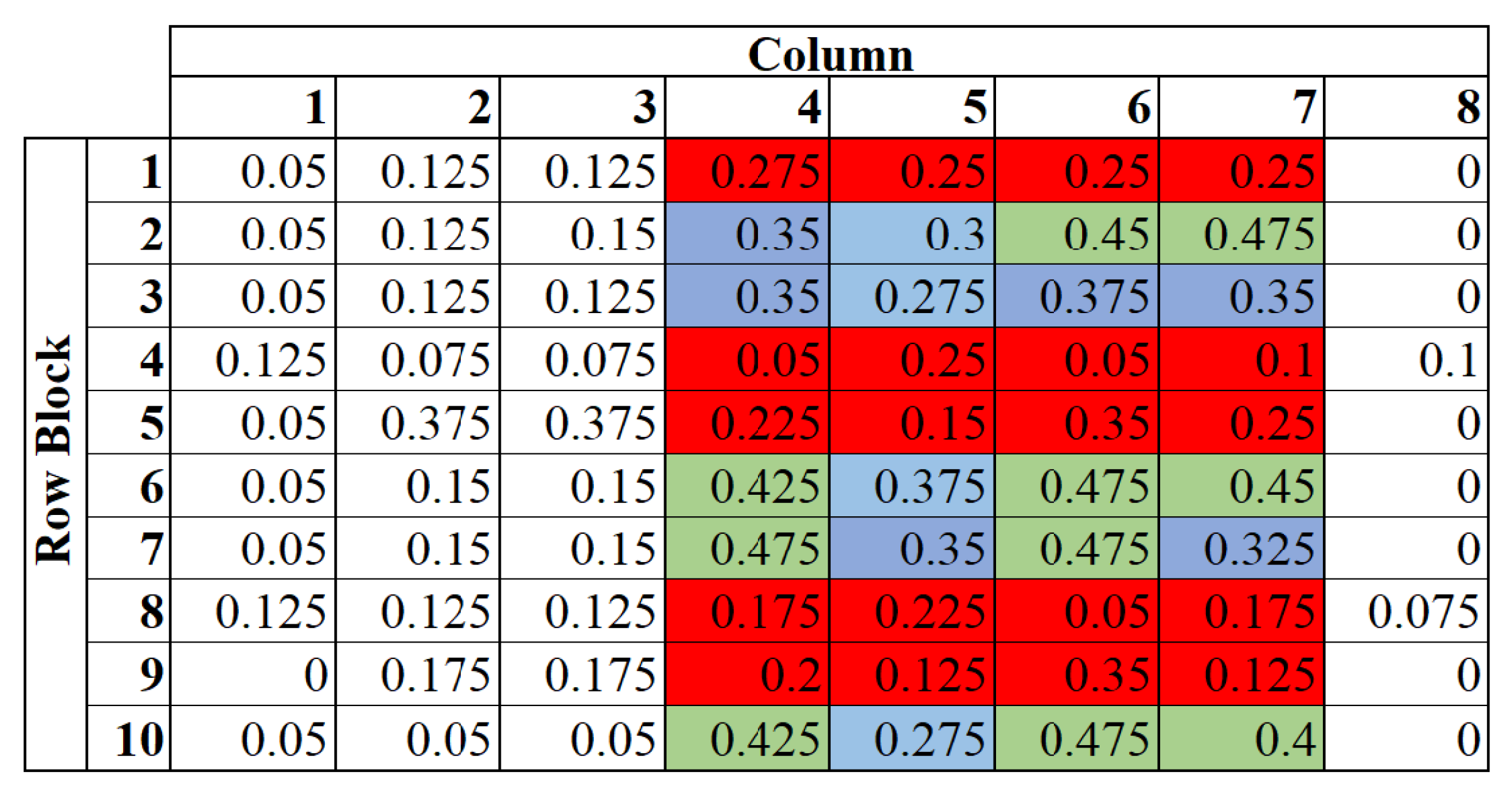
Figure 11 shows the average inter-HD of all 10 chips for first 80 rows (8 rows per row block). From the result, we observe that inter-HD of Col 0, 1, 2 and 7 are poor as they are stuck to either 0 or 1. Furthermore, we also observe that certain address rows provide good inter-HD (green/blue) whereas other rows provide very poor inter-HD (red). We propose the following techniques to improve the inter-HD.

3.3.1. Improving Column Performance

We propose writing the same address twice with write time corresponding to 75% switching probability. The first/second response will have 75%/50% number of 1s. Since the two responses are purely random, we propose using first response of columns 3–6 as the response of bad columns (i.e., columns 0, 1, 2 and 7) and the second response of columns 3–6 as their own response. Therefore, we avoid masking of unusable columns and restore the PUF bandwidth to 8 bits per challenge. The response obtained for bad columns are enforced on them with relaxed write latency for subsequent authentication. This technique exploits the fact that each bit of MRAM can produce more than one random bit of information.

3.3.2. Improving Row Performance

By improving column performance, inter-die HD of stuck columns improves by 1.7X-4X (individually). However, total inter-HD remains poor (≈28%) due to poor performance of some rows that exhibit 0% inter-HD. Further, we observe that the rows with poor inter-HD are mainly stuck to either all 0s or all 1s. The rows stuck to 0s (perhaps due to higher thermal stability) are fixed by re-writing them with higher write time to trigger statistical flipping. The row stuck to all 1s (perhaps due to low thermal stability) are fixed by re-writing them with lower write time.
After improving row/column performances, we obtain inter-HD of 46.25% which is close to the ideal value. The proposed improvement technique incurs one-time energy (≈2.7X) and computational overhead during the enrollment phase. Furthermore, it should be noted that, alternative improvement technique of masking the rows/blocks of rows incurs significant area overhead. For the case of Figure 11, 75% bits are lost if masking is implemented. The energy, bandwidth and area of the wPUF are 0.14 pJ/bit, 0.34 Gbit/s, 0.385 μm2/bit (including all peripheral circuits). Table 2 benchmarks proposed wPUF with existing MRAM/STTRAM PUFs. We can observe that the proposed PUF is comparable to prior works. It should be noted that (i) the proposed PUF is based on a commercial chip which gives practical process variation; and, (ii) the data bus is 8 bit long, therefore the bandwidth is comparatively low.

4. TRNG

TRNG generates true random number based on some random inherent noise. For memory-based TRNG, the memory bitcell is biased at the 50% switching probability point at which the bit stabilizes to either 1 or 0 depending on the noise. Therefore, the written value is highly unpredictable, varies from chip to chip and strongly depends on the operating conditions and noise. In this section, we present the proposed TRNG and analyze its performance using experimental results.

4.1. Proposed TRNG

Figure 12 presents the algorithm to realize TRNG from the MRAM chip. First, the memory address is flushed, i.e., 0 s are written to all bits. Next, the write time is set to 75% switching probability and 1 s are written to the addresses. The 75% switching probability means the ratio of 1 s to 0 s will be 75%. The data written is considered as the first random number. Then, the same address is written again with all 1 s with the same write time. We notice that the ratio of 1 s to 0 s reduces to ≈50% (observation (b), Section 2) on the second write. This is the second random number. Similarly, when we write for the 3rd time the 1 s to 0 s ratio drops to ≈35% which gives out the 3rd random number. By repeating the same process for different write times and different addresses, we can generate more random numbers.
Since it is impossible to bias individual MRAM bits to their 50% switching probability using a common write latency, we bias the MRAM using three different switching probabilities and extract all possible outcomes from n-bits. For example, biasing 4 bits at 50% switching probability means that on an average, 2 bits out of 4 will be set to ‘1’. This will produce 6 outcomes out of 16 possibilities (i.e., 1100, 0110, 0011, 1010, 1001 and 0101). Biasing at 75% switching probabilities mean 3 bits will be set to 1s producing 4 new outcomes (1110, 0111, 1011 and 1101). Biasing at 35% switching probabilities mean 1 bit will be set to 1s producing 4 new outcomes (0001, 0010, 0100 and 1000). Note that the remaining two outcomes (0000/1111) are also produced by TRNG but with lower frequency.
Write operation of any spintronic memory suffers due to temperature and V D D variation. Therefore, TRNG can be biased to some preferential values and behaves as Pseudo Random Number Generator (PRNG). Tracking of V D D and temperature are needed for magnetic TRNG to change the biasing conditions accordingly and achieve desired switching probability.
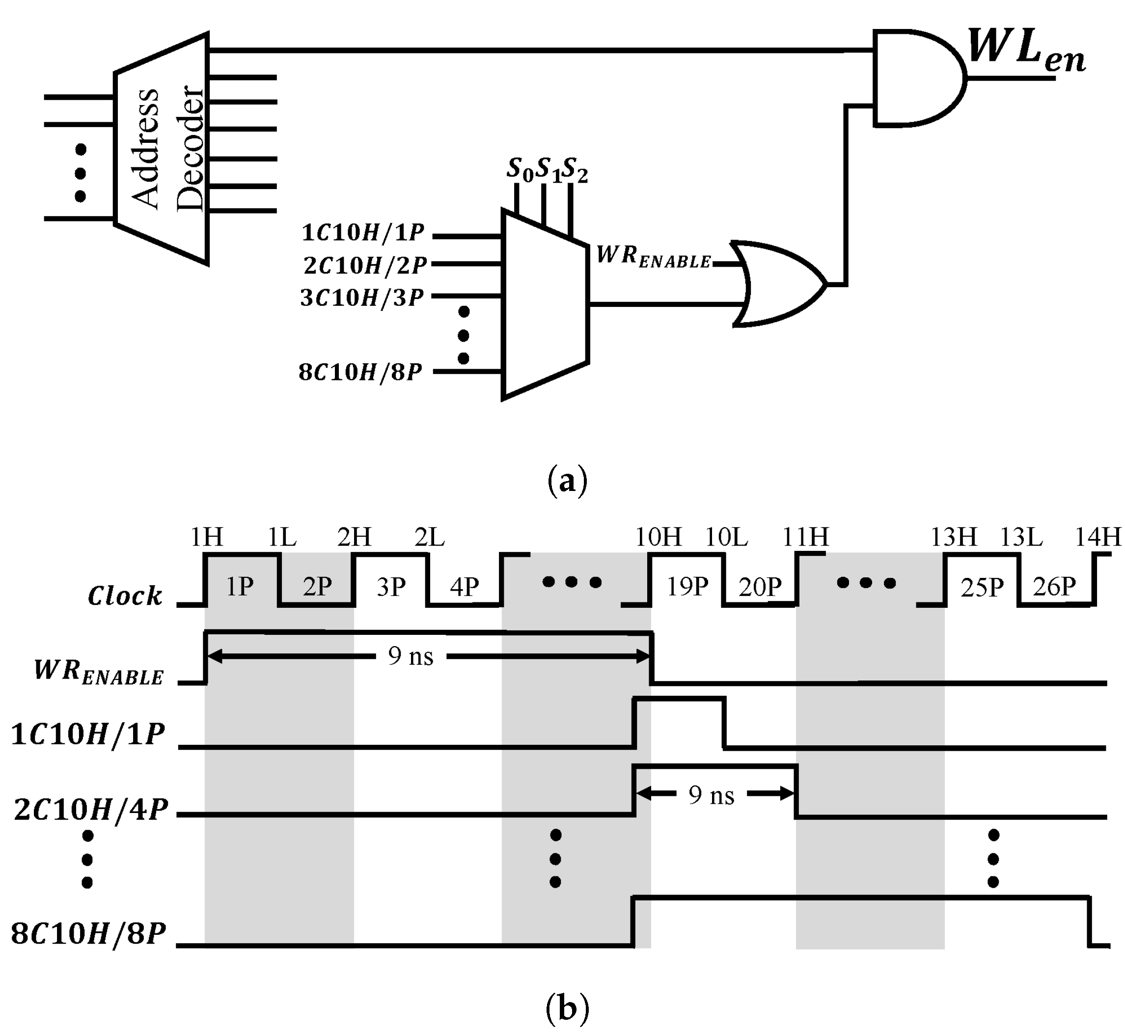
We assume that the processor can track V D D and temperature to select appropriate write time. Figure 13a shows the proposed circuit and Figure 13b shows the timing waveform to implement variable write time. For this example, we have assumed that the processor runs at 1 GHz (time period 1 ns) and write time can vary from 9 ns to 13 ns depending on operating condition. Therefore, from this circuit we can select write time with a step size of 0.5 ns in that range (by asserting WR_ENABLE and any of the other 8 pulses). If finer step size is required, more pulses can be generated with less duty cycle. However, in that case, the MUX will have more inputs (4:1 MUX (16 pulses in total) for 0.25 ns granularity).

4.2. Performance Analysis

(a) Entropy: Entropy of TRNG defines the randomness of the generated data. Entropy can be calculated with the following equation [29]:
E = i = 2 2 p i l o g 2 ( p i )
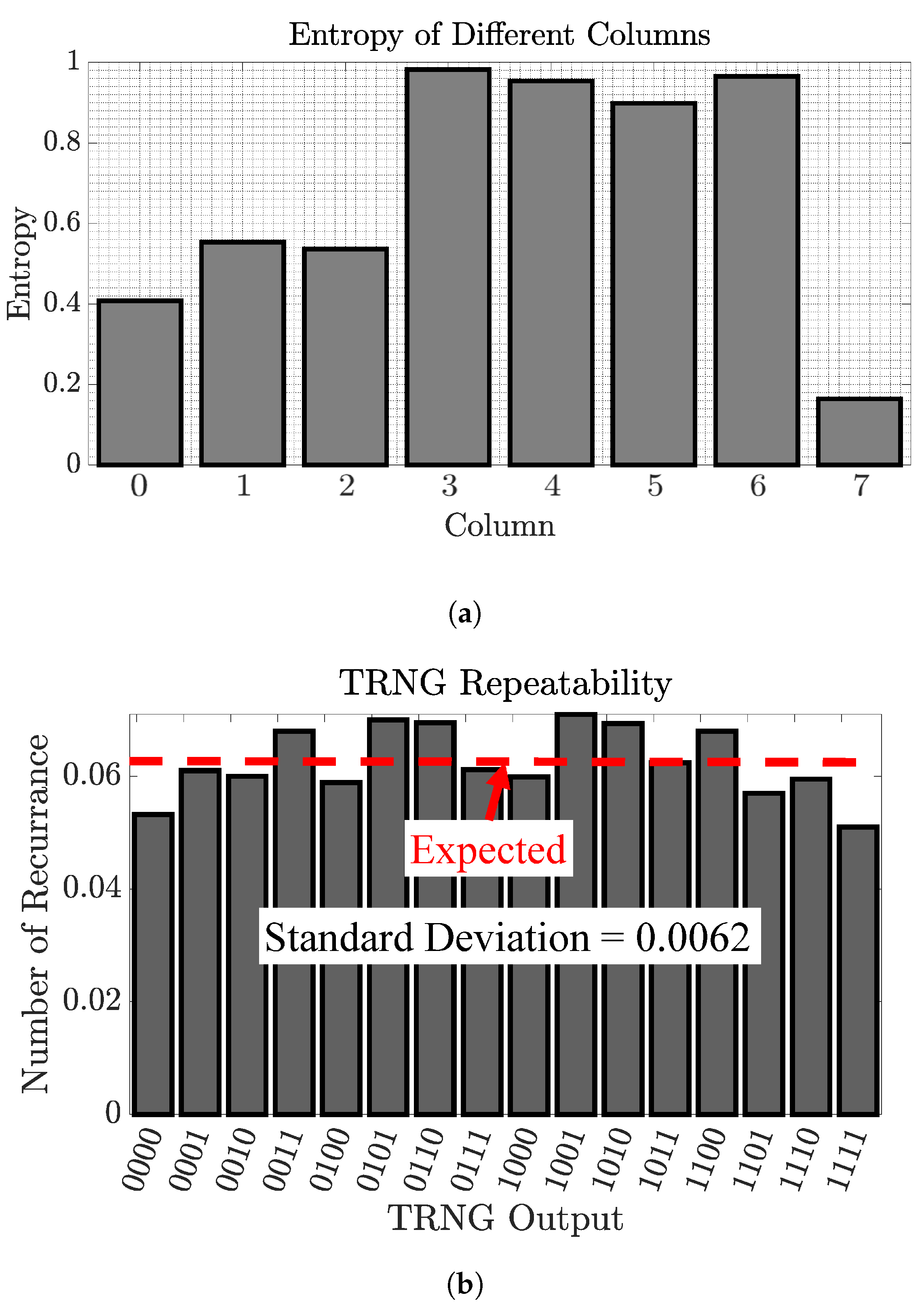
where p1 and p2 are probability of 1 s and 0 s respectively in a n-bit long data stream. For an ideal TRNG, the entropy is 1. We have calculated entropy of all chips column-wise and the average entropy is shown in Figure 14a. It is evident that, columns 0, 1, 2, and 7 show poor randomness (explained in previous section) and therefore needs to be masked. After masking, the proposed TRNG offers an entropy of 0.95.
(b) Repeatability: Repeatability is another important metric to evaluate TRNG performance. Ideally, a TRNG should only repeat when all other possible cases are already covered. For example, for a 4-bit TRNG, the generated value should only repeat when all the 16 possible values are generated. However, practically this is very difficult to achieve. In the proposed TRNG algorithm, we are able to get all possible outcomes with small standard deviation (0.0062) and the correlation coefficient is calculated as 0.05. Figure 14b shows the outcomes of 10,000 cases for the proposed TRNG.
The energy, bandwidth and area of the proposed TRNG are found to be 0.41 pJ/bit, 0.12 Gbit/s and 0.769 μm2/bit (including all peripheral circuits). We have also tested our TRNG outputs with NIST STS randomness test (summarized in Table 3). It is evident from the results that the proposed TRNG achieves excellent quality. Table 4 benchmarks the proposed TRNG with existing MRAM/STTRAM TRNG. We can observe that the proposed PUF is comparable to prior works and its energy (bandwidth) is significantly lower (higher) than others.

5. Discussions

VDD and temperature tracking: Any biasing technique to achieve a particular switching probability (pulse width/duration) is susceptible to V D D /temperature. Therefore, V D D /temperature tracking is required to select appropriate biasing condition which can be designed based on statistical data.
Considerations to other magnetic memory architecture: Consecutive writes of 1 s with less than T 1 1 write time gives 75%, 50% and 35% of number of 1 s in the data (observation (c)) for the toggle MRAM chip. However, three different write times ( T 75 % / T 50 % / T 35 % ) can be implemented for other memory (that does not show this behavior).
Novelty of this work: Prior works consider bitwise normal distribution of switching probability. However, there are several practical challenges with the real memory implementation. First, it offers a narrow distribution with some columns/rows stuck at 0/1. Besides, the real memory chip does not provide granular access to each individual bits and for that biasing of the bits cannot be bitwise tailored. Even custom biasing for each row is impractical. To the best of our knowledge, we make the first attempt to systematically understand and address these practical challenges in this paper.
Note that we have selected MRAM since it is very promising due to its low static and read power consumption. However, the proposed post-processing techniques to improve the inter-HD of PUF and entropy of TRNG are applicable to other memory technologies.
TRNG robustness to Machine Learning Attack: Random Number Generator (RNG) can be vulnerable to machine learning attack [30]. However, an RNG can be robust against such attack if the non-linearity is very high (i.e., no repetitive patterns in outcomes of RNG). Since the response of the proposed TRNG is non-linearly dependent on numerous parameters, e.g., write pulse width, write voltage and temperature due to non-linear magnetization dynamics of MRAM free layer, the proposed MRAM TRNG is expected to be robust against machine learning attack.

6. Conclusions

We have investigated TRNG and PUF implementation using magnetic memory and manipulation of write time and number of writes. We have analyzed the practical implications of designing TRNG/PUF using commercial MRAM and addressed these issues to achieve high quality.

Author Contributions

Conceptualization, M.N.I.K. and S.G.; methodology, M.N.I.K.; software, A.A.-S.; validation, M.N.I.K., C.Y.C., S.H.L. and A.A.-S.; formal analysis, M.N.I.K.; investigation, M.N.I.K.; resources, S.G.; data curation, C.Y.C. and S.H.L.; writing—M.N.I.K., A.A.-S. and S.G.; original draft preparation, M.N.I.K. and A.A.-S.; writing—review and editing, M.N.I.K., A.A.-S. and S.G.; visualization, M.N.I.K.; supervision, M.N.I.K. and S.G.; project administration, M.N.I.K. and S.G.; funding acquisition, S.G. All authors have read and agreed to the published version of the manuscript.

Funding

This work is supported by Semiconductor Research Corporation (2847.001 and 3011.001) and National Science Foundation (CNS-1722557, CCF-1718474, DGE-1723687, OIA-2040667 and DGE-1821766).

Conflicts of Interest

The authors declare no conflict of interest.

References

  1. Khan, M.N.I.; Bhasin, S.; Yuan, A.; Chattopadhyay, A.; Ghosh, S. Side-Channel Attack on STTRAM Based Cache for Cryptographic Application. In Proceedings of the 2017 IEEE International Conference on Computer Design (ICCD), Boston, MA, USA, 5–8 November 2017; pp. 33–40. [Google Scholar]
  2. Lin, C.W.; Ghosh, S. Novel self-calibrating recycling sensor using Schmitt-Trigger and voltage boosting for fine-grained detection. In Proceedings of the Sixteenth International Symposium on Quality Electronic Design, Santa Clara, CA, USA, 2–4 March 2015; pp. 465–469. [Google Scholar]
  3. Herder, C.; Yu, M.; Koushanfar, F.; Devadas, S. Physical Unclonable Functions and Applications: A Tutorial. Proc. IEEE 2014, 102, 1126–1141. [Google Scholar] [CrossRef]
  4. Suh, G.E.; Devadas, S. Physical Unclonable Functions for Device Authentication and Secret Key Generation. In Proceedings of the 2007 44th ACM/IEEE Design Automation Conference, San Diego, CA, USA, 4–8 June 2007; pp. 9–14. [Google Scholar]
  5. Tsoi, K.H.; Leung, K.H.; Leong, P.H.W. Compact FPGA-based true and pseudo random number generators. In Proceedings of the 11th Annual IEEE Symposium on Field-Programmable Custom Computing Machines, FCCM 2003, Napa, CA, USA, 9–11 April 2003; pp. 51–61. [Google Scholar]
  6. Magnetic Tamper Detection Using Low-PowerHall Effect Sensors. Available online: http://www.ti.com/lit/ug/tidub69/tidub69.pdf (accessed on 12 January 2021).
  7. Miura, N.; Fujimoto, D.; Tanaka, D.; Hayashi, Y.-I.; Homma, N.; Aoki, T.; Nagata, M. A local EM-analysis attack resistant cryptographic engine with fully-digital oscillator-based tamper-access sensor. In Proceedings of the 2014 Symposium on VLSI Circuits Digest of Technical Papers, Honolulu, HI, USA, 10–13 June 2014; pp. 1–2. [Google Scholar]
  8. Ghosh, S.; Basak, A.; Bhunia, S. How Secure Are Printed Circuit Boards Against Trojan Attacks? IEEE Design Test 2015, 32, 7–16. [Google Scholar] [CrossRef]
  9. Khan, M.N.I.; Nagarajan, K.; Ghosh, S. Hardware Trojans in Emerging Non-Volatile Memories. In Proceedings of the 2019 Design, Automation & Test in Europe Conference & Exhibition (DATE), Florence, Italy, 25–29 March 2019; pp. 396–401. [Google Scholar]
  10. Khan, M.N.I.; De, A.; Ghosh, S. Cache-Out: Leaking Cache Memory Using Hardware Trojan. IEEE Trans. Very Large Scale Integr. (VLSI) Syst. 2020, 28, 1461–1470. [Google Scholar] [CrossRef]
  11. Mazady, A.; Rahman, M.T.; Forte, D.; Anwar, M. Memristor PUF—A Security Primitive: Theory and Experiment. IEEE J. Emerg. Sel. Top. Circuits Syst. 2015, 5, 222–229. [Google Scholar] [CrossRef]
  12. Iyengar, A.; Ghosh, S.; Ramclam, K.; Jang, J.-W.; Lin, C.-W. Spintronic PUFs for Security, Trust, and Authentication. J. Emerg. Technol. Comput. Syst. 2016, 13, 1–5. [Google Scholar] [CrossRef]
  13. Ghosh, S.; Govindaraj, R. Spintronics for associative computation and hardware security. In Proceedings of the 2015 IEEE 58th International Midwest Symposium on Circuits and Systems (MWSCAS), Fort Collins, CO, USA, 2–5 August 2015; pp. 1–4. [Google Scholar]
  14. Chen, A. Utilizing the Variability of Resistive Random Access Memory to Implement Reconfigurable Physical Unclonable Functions. IEEE Electron Device Lett. 2015, 36, 138–140. [Google Scholar] [CrossRef]
  15. Zhang, L.; Fong, X.; Chang, C.; Kong, Z.H.; Roy, K. Highly reliable memory-based Physical Unclonable Function using Spin-Transfer Torque MRAM. In Proceedings of the 2014 IEEE International Symposium on Circuits and Systems (ISCAS), Melbourne, VIC, Australia, 1–5 June 2014; pp. 2169–2172. [Google Scholar]
  16. Chen, A.; Hu, X.S.; Jin, Y.; Niemier, M.; Yin, X. Using emerging technologies for hardware security beyond PUFs. In Proceedings of the 2016 Design, Automation & Test in Europe Conference & Exhibition (DATE), Dresden, Germany, 14–18 March 2016; pp. 1544–1549. [Google Scholar]
  17. Das, J.; Scott, K.; Rajaram, S.; Burgett, D.; Bhanja, S. MRAM PUF: A Novel Geometry Based Magnetic PUF With Integrated CMOS. IEEE Trans. Nanotechnol. 2015, 14, 436–443. [Google Scholar] [CrossRef]
  18. Vatajelu, E.I.; Natale, G.D.; Prinetto, P. Zero bit-error-rate weak PUF based on Spin-Transfer-Torque MRAM memories. In Proceedings of the 2017 IEEE 2nd International Verification and Security Workshop (IVSW), Thessaloniki, Greece, 3–5 July 2017; pp. 128–133. [Google Scholar]
  19. Khaleghi, S.; Vinella, P.; Banerjee, S.; Rao, W. An STT-MRAM based strong PUF. In Proceedings of the 2016 IEEE/ACM International Symposium on Nanoscale Architectures (NANOARCH), Beijing, China, 18–20 July 2016; pp. 129–134. [Google Scholar]
  20. Seki, A.F.T.; Kubota, K.Y.H.; Imamura, H.; Yuasa, S.; Ando, K. Spin dice: A scalable truly random number generator based on spintronics. Appl. Phys. Express 2014, 7, 083001. [Google Scholar]
  21. Oosawa, S.; Konishi, T.; Onizawa, N.; Hanyu, T. Design of an STT-MTJ based true random number generator using digitally controlled probability-locked loop. In Proceedings of the 2015 IEEE 13th International New Circuits and Systems Conference (NEWCAS), Grenoble, France, 7–10 June 2015; pp. 1–4. [Google Scholar]
  22. Fong, X.; Chen, M.; Roy, K. Generating true random numbers using on-chip complementary polarizer spin-transfer torque magnetic tunnel junctions. In Proceedings of the 72nd Device Research Conference, Santa Barbara, CA, USA, 22–25 June 2014; pp. 103–104. [Google Scholar]
  23. Vatajelu, E.I.; Natale, G.D.; Prinetto, P. Security primitives (PUF and TRNG) with STT-MRAM. In Proceedings of the 2016 IEEE 34th VLSI Test Symposium (VTS), Las Vegas, NV, USA, 25–27 April 2016; pp. 1–4. [Google Scholar]
  24. Khan, M.N.I.; Cheng, C.Y.; Lin, S.H.; Ash-Saki, A.; Ghosh, S. A Morphable Physically Unclonable Function and True Random Number Generator using a Commercial Magnetic Memory. In Proceedings of the 2020 21st International Symposium on Quality Electronic Design (ISQED), Santa Clara, CA, USA, 25–26 March 2020; p. 197. [Google Scholar]
  25. Basys3TM FPGA Board Reference Manual. Available online: reference.digilentinc.com/_media/basys3:basys3_rm.pdf (accessed on 12 January 2021).
  26. The Standard for Superior Measurements. Available online: https://www.keysight.com/us/en/assets/7018-04261/data-sheets/5991-3904.pdf (accessed on 12 January 2021).
  27. Zhang, X.; Sun, G.; Zhang, Y.; Chen, Y.; Li, H.; Wen, W.; Di, J. A novel PUF based on cell error rate distribution of STT-RAM. In Proceedings of the 2016 21st Asia and South Pacific Design Automation Conference (ASP-DAC), Macau, China, 25–28 January 2016; pp. 342–347. [Google Scholar]
  28. Zhang, L.; Fong, X.; Chang, C.; Kong, Z.H.; Roy, K. Optimizating Emerging Nonvolatile Memories for Dual-Mode Applications: Data Storage and Key Generator. IEEE Trans. Comput. Aided Des. Integr. Circuits Syst. 2015, 34, 1176–1187. [Google Scholar] [CrossRef]
  29. Shannon, C.E. A mathematical theory of communication. Bell Syst. Tech. J. 1948, 27, 379–423. [Google Scholar] [CrossRef] [Green Version]
  30. Kim, J.; Nili, H.; Truong, N.D.; Ahmed, T.; Yang, J.; Jeong, D.S.; Sriram, S.; Ranasinghe, D.C.; Ippolito, S.; Chun, H.; et al. Nano-Intrinsic True Random Number Generation: A Device to Data Study. IEEE Trans. Circuits Syst. Regul. Pap. 2019, 66, 2615–2626. [Google Scholar]
Figure 1. Morphable security primitive using Magnetoresistive RAM (MRAM).
Jlpea 11 00005 g001
Figure 2. Toggle MRAM bitcell containing one Magnetic Tunnel Junction (MTJ) and one access transistor.
Jlpea 11 00005 g002
Figure 3. Write cycle of MRAM chip. Note that the chip requires maximum of 15 ns of write enable (low) signal for successful write.
Jlpea 11 00005 g003
Figure 4. Read cycle of MRAM chip.
Jlpea 11 00005 g004
Figure 5. MRAM (a) write and (b) read waveforms. Note that with 12 ns of write enable (low) signal, data (0x0C) is written successfully (to address 0x00 0180).
Jlpea 11 00005 g005
Figure 6. Experimental setup. The MRAM PCB (inset) is mounted on top of Basys3 for noise reduction.
Jlpea 11 00005 g006
Figure 7. Cumulative Distribution Function (CDF) of write success of 3 chips (out of 10). These 3 chips exhibit maximum write time variation.
Jlpea 11 00005 g007
Figure 8. Number of consecutive writes vs. percentage of 1s in the data.
Jlpea 11 00005 g008
Figure 9. Switching probability distribution of 16 KB MRAM. First 16384 rows are grouped to 16 blocks (1024 rows/block).
Jlpea 11 00005 g009
Figure 10. Two phases of wPUF, (a) Enrollment phase; (b) Authentication phase.
Jlpea 11 00005 g010
Figure 11. Average inter-HD of 10 chips for first 80 rows (8 rows/block).
Jlpea 11 00005 g011
Figure 12. Algorithm of the proposed True Random Number Generator (TRNG).
Jlpea 11 00005 g012
Figure 13. (a) Circuit and (b) timing waveform to implement specific write time selection for achieving desired switching probability.
Jlpea 11 00005 g013
Figure 14. (a) Average entropy of all chips measured column-wise; (b) repeatability of TRNG outcomes out of 10,000 responses.
Jlpea 11 00005 g014
Table 1. Characteristic of the MRAM Chip.
ParameterValue
Capacity16 Mbit
Read/Write Cycle35 ns
Address/Data Bus Length21/8
Retention Time>20 years
AC stand by Current9–14 mA
AC Active Current (Read/Write)60–68 mA/152–180 mA
Table 2. Performance comparison of different MRAM/STTRAM PUFs with the proposed wPUF.
PUFsInter-Die HD
(%)
Inter-Die HD
(%)
EntropyArea (MTJ)
(μm2)
Bandwidth
(Gbit/s)
Energy/bit
(pJ)
Experimental
[15]-50.10.9850.0466.4-No
[17]0.02470.996.74
(64 bit)
12.8-Yes
[27]7.7660.6-0.0656.42.42No
[28]-49.890.950.0056.40.001No
wPUF
(This Work)
022.5 (before)
46.26 (after)
0.950.385 10.340.14 1Yes
1 includes decoder, sense amp, and other peripheral circuitry and considers 100 mil × 100 mil of die size for TSOP-II IC package.
Table 3. Summary of NIST Suite Statistical Result.
NIST Statistical Testp-ValueProportionResult
Frequency0.349865199/200Pass
Block Frequency0.257217199/200Pass
Cumulative Sums0.393322199/200Pass
Discrete Fourier Transform0.476393199/200Pass
Approximate Entropy0.844361200/200Pass
Table 4. Performance comparison of different MRAM/STTRAM TRNG with proposed TRNG.
TRNGCorrelationEntropyArea (MTJ)
(μm2)
Bandwidth
(Gbit/s)
Energy/bit
(pJ)
Experimental
[20]0.003-0.0140.000514.97Yes
[21]--0.0085 10.0833 10.3386 1Yes
This Work0.050.950.769 20.120.41 2Yes
1 Considering 3 ns of read time; 2 Includes all peripheral circuitry and considers only 4 bits of each row. Thus, area is 2× of wPUF.
Publisher’s Note: MDPI stays neutral with regard to jurisdictional claims in published maps and institutional affiliations.