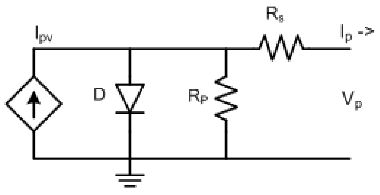
Figure 1.
Single photo-voltaic (PV) cell equivalent circuit.
Figure 1.
Single photo-voltaic (PV) cell equivalent circuit.
Figure 2.
IV and PV characteristics of a solar cell at five various irradiations.
Figure 2.
IV and PV characteristics of a solar cell at five various irradiations.
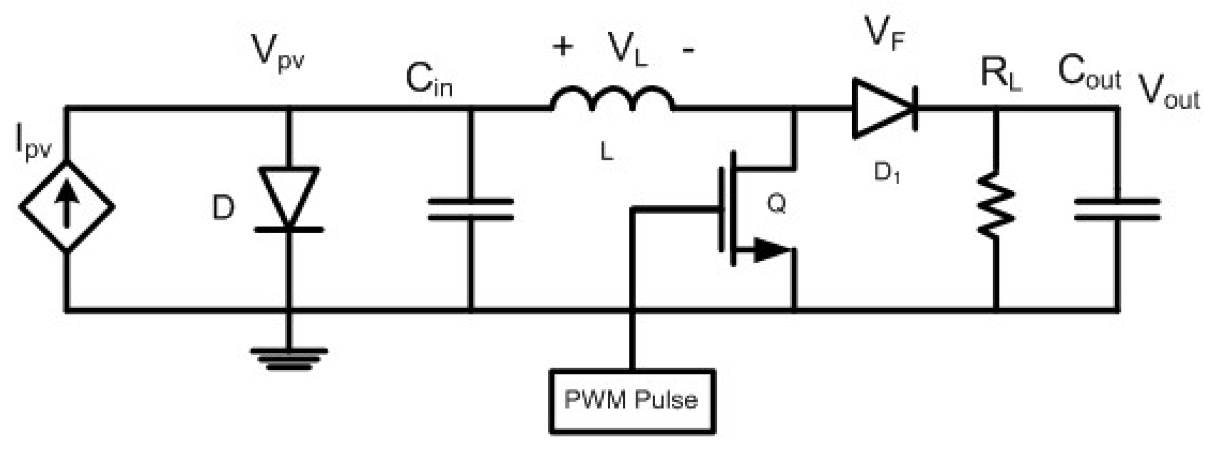
Figure 3.
An impedance-matched PV boost converter.
Figure 3.
An impedance-matched PV boost converter.
Figure 4.
Boost converter when Metal Oxide Silicon Field Effect Transistor’s (MOSFET) switch is on.
Figure 4.
Boost converter when Metal Oxide Silicon Field Effect Transistor’s (MOSFET) switch is on.
Figure 5.
Boost converter when MOSFET switch is off.
Figure 5.
Boost converter when MOSFET switch is off.
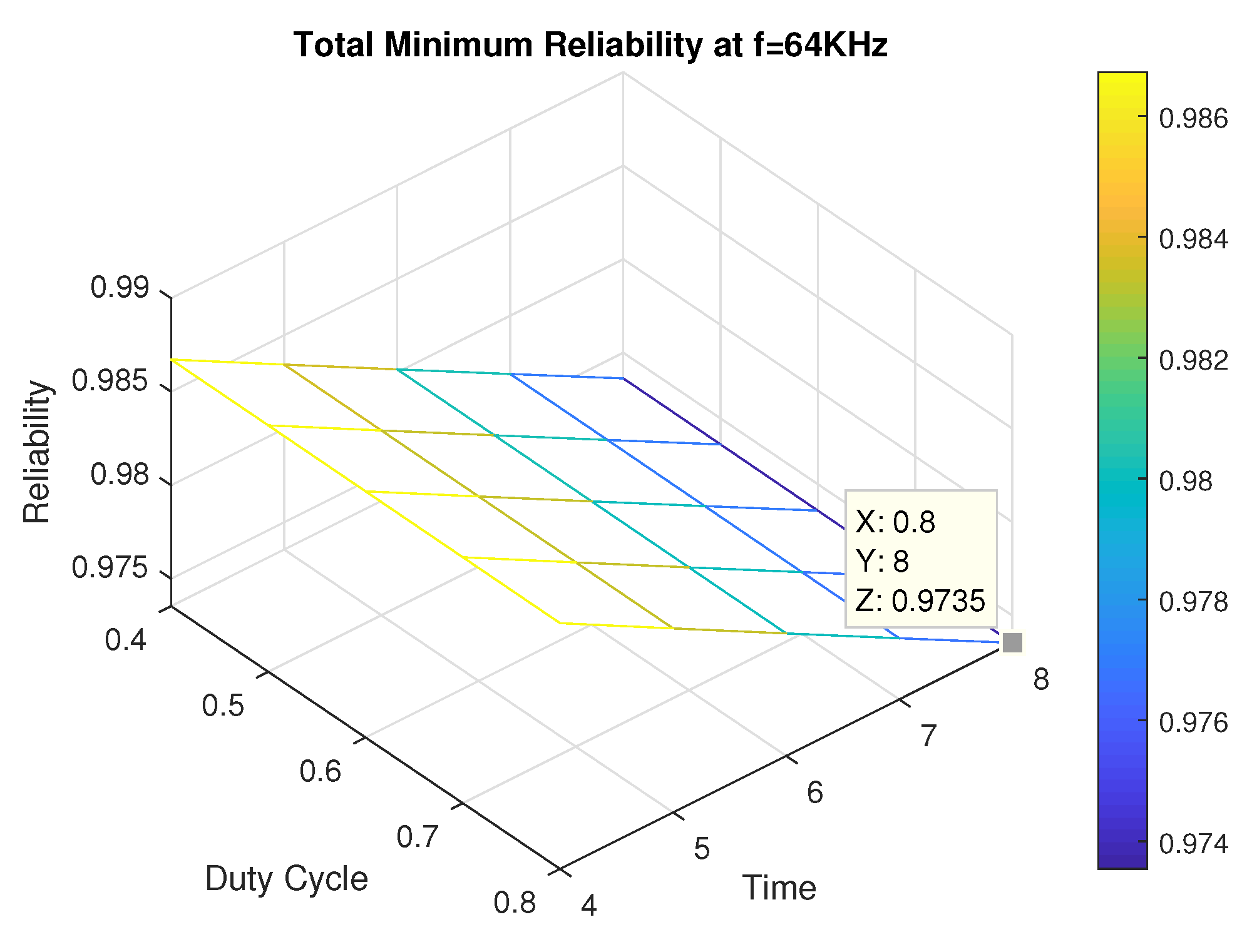
Figure 6.
Total minimum reliability at D = 0.8.
Figure 6.
Total minimum reliability at D = 0.8.
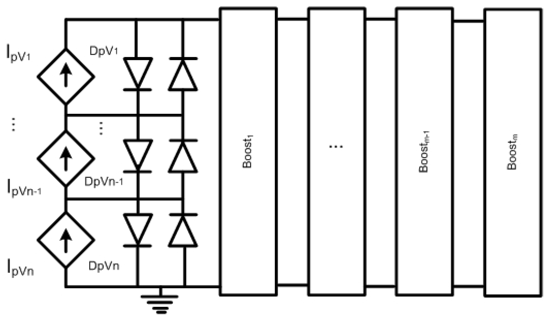
Figure 7.
A matrix [n m] of PV cells and boost converters.
Figure 7.
A matrix [n m] of PV cells and boost converters.
Figure 8.
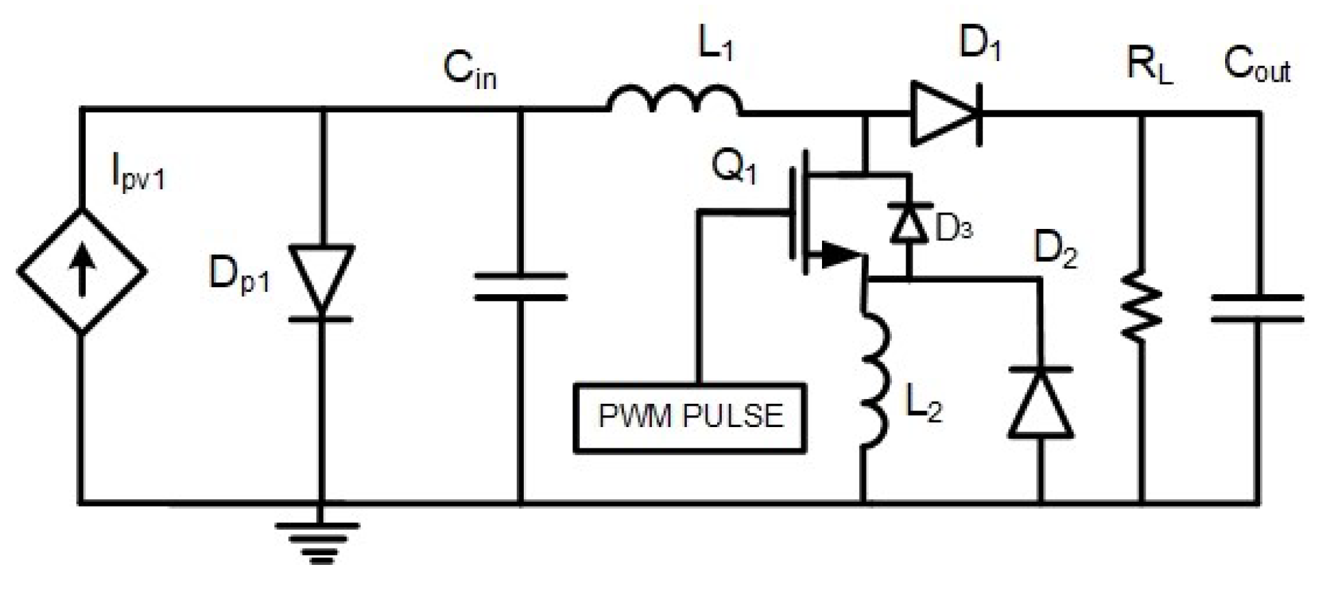
Proposed recycled boost converter, matrix [1 1].
Figure 8.
Proposed recycled boost converter, matrix [1 1].
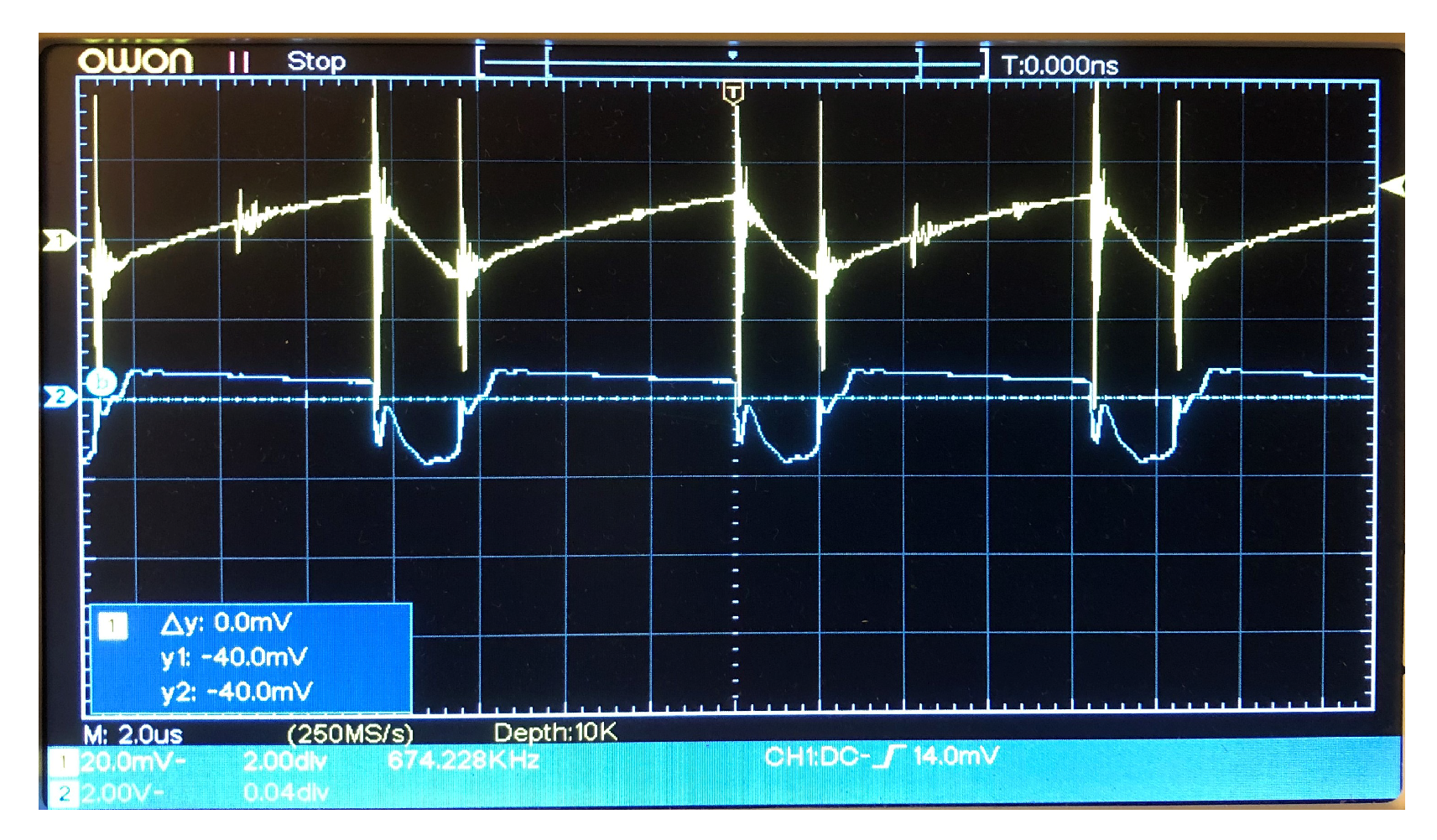
Figure 9.
Typical waveform of the proposed boost converter.
Figure 9.
Typical waveform of the proposed boost converter.
Figure 10.
Proposed synchro-recycled boost converter, matrix [3 1].
Figure 10.
Proposed synchro-recycled boost converter, matrix [3 1].
Figure 11.
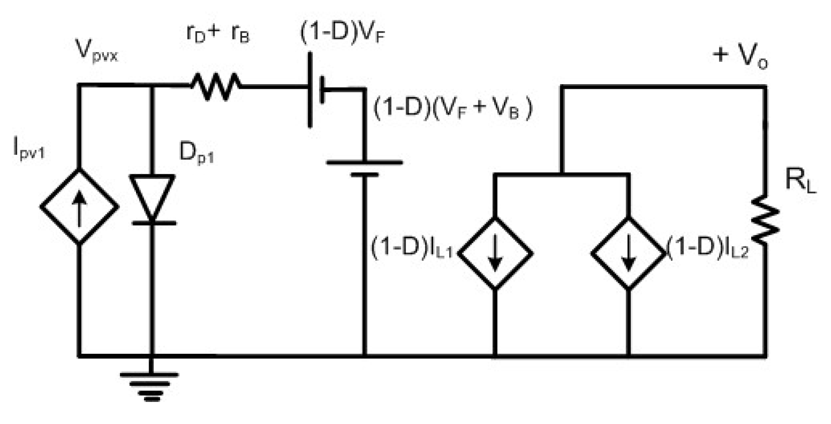
Averaged DC model of the recycled boost converter, matrix [1 1].
Figure 11.
Averaged DC model of the recycled boost converter, matrix [1 1].
Figure 12.
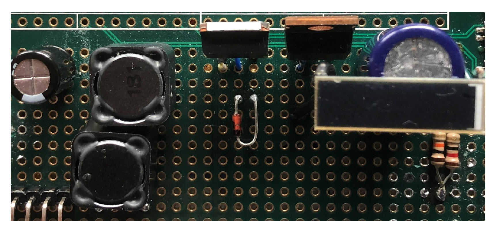
The prototype implementation of synchro-recycled matrix [2 1].
Figure 12.
The prototype implementation of synchro-recycled matrix [2 1].
Figure 13.
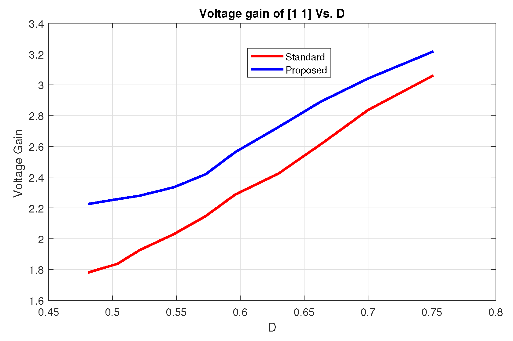
The voltage gain of the proposed recycled and standard boost converter vs. duty cycle, matrix [1 1].
Figure 13.
The voltage gain of the proposed recycled and standard boost converter vs. duty cycle, matrix [1 1].
Figure 14.
The current (top) and voltage waveform of for a matrix boost [1 1].
Figure 14.
The current (top) and voltage waveform of for a matrix boost [1 1].
Table 1.
Comparison between various MOSFETS and DIODES.
Table 1.
Comparison between various MOSFETS and DIODES.
| MOSFET | Body Diode (V) |
|---|
| Csd16570q5b | 1.00 |
| IRFz34 | 1.6 |
| IRF501 | 1.3 |
| RV1C002UN | 1.2 |
| SI3900DV-T1-GE3 | 1.1 |
| Diode | Forward Voltage (V) |
| 1n4148 | 1 at 10 mA |
| BYS10-25 | 1 at 1 A |
| Bat54htig | 0.5 at 10 mA |
| S1 A/B | 1.1 at 1 A |
| NSR0520V2T1G | 0.48 at 500 mA |
Table 2.
A comparison between efficiency and output voltage of two different MOSFETs.
Table 2.
A comparison between efficiency and output voltage of two different MOSFETs.
| MOSFET | () | | (V) | (V) | |
|---|
| IRFZ34 | 0.05 | 46 | 1.6 | 1.09 | 69 |
| CSD1657Q5B | 0.00068 | 124 | 1 | 1.34 | 58 |
Table 3.
Temperature factor of components.
Table 3.
Temperature factor of components.
| MOSFET | |
| DIODE | |
| Inductor | |
Table 4.
Failure rate models for the components.
Table 4.
Failure rate models for the components.
| MOSFET | = |
| DIODE | = |
| INDUCTOR | = |
Table 5.
A comparison between standard and proposed boost characteristics currents, [1 1], f = 106 KHz, D = 0.7.
Table 5.
A comparison between standard and proposed boost characteristics currents, [1 1], f = 106 KHz, D = 0.7.
| Inductor Currents (RMS) | (mA) |
|---|
| 4.58 |
| 3.22 |
| 7.06 |
| Diode Currents (Ave) | (mA) |
| Standard | 1.56 |
| Proposed | 1.96 |
| Output Voltage | (mV) |
| Standard | 592 |
| Proposed | 800 |
Table 6.
Component description list.
Table 6.
Component description list.
| MOSFET N Type | IRFz34, IRF501, D2 Pack |
|---|
| Inductor | SPR1210A-181MCT, 180 uH |
| Capacitor | UKL1E101KPDANA 1000 uF |
| Diode Schottky | MBR0520LT1, 1SS394TE85LFCT |
| PV cell | KXOB22-12X1F |
| PWM Pulser | PIC Micro-Controller |
Table 7.
A comparative result between standard and recycled boost using matrix [1 1] at strong overcast, f = 125 KHz, D Error = 1%.
Table 7.
A comparative result between standard and recycled boost using matrix [1 1] at strong overcast, f = 125 KHz, D Error = 1%.
| Topology | (V) | | | | R |
|---|
| Standard | 1.295 | 38 | 2.3 | 9.98 | 0.9737 |
| Recycled | 1.670 | 87.1 | 2.8 | 6.53 | 0.9680 |
Table 8.
Performance comparison between standard and proposed recycled [3 1] matrix at = 490 , non-matched, f = 83.4 KHz, D = 0.549 for the same Gate Loss, IRF501, (mW).
Table 8.
Performance comparison between standard and proposed recycled [3 1] matrix at = 490 , non-matched, f = 83.4 KHz, D = 0.549 for the same Gate Loss, IRF501, (mW).
| Topology | (V) | | | |
|---|
| Standard | 2.423 | 45.65 | 1.64 | 7.36 |
| Recycled | 2.690 | 73.75 | 1.66 | 4.37 |
Table 9.
Performance comparison between standard and recycled [3 1], f = 80 KHz, = 490 , with D = 0.57 at strong overcast with a matched impedance.
Table 9.
Performance comparison between standard and recycled [3 1], f = 80 KHz, = 490 , with D = 0.57 at strong overcast with a matched impedance.
| Operating Parameters | Standard Boost | Recycled Boost |
|---|
| (V) | 2.00 | 2.4 |
| (mW) | 8.16 | 11.75 |
| Input Power (mW) | 12.96 + 1.16 * | 12.39 + 1.16 * |
| Efficiency (%) | 57.8 | 86.7 |
| VCE | 1.85 | 1.71 |
| Reliability (%) | 0.9716 | 0.9680 |
Table 10.
Performance comparison between standard and proposed synchro-recycled matrix [3 1], f = 83.4 KHz, Non-matched with D = 0.58 and MBR0520LT1, IRFZ34.
Table 10.
Performance comparison between standard and proposed synchro-recycled matrix [3 1], f = 83.4 KHz, Non-matched with D = 0.58 and MBR0520LT1, IRFZ34.
| Operating Parameters | Standard | Synchro-Recycled |
|---|
| (V) | 1.38 | 1.431 |
| (mW) | 3.886 | 4.179 |
| Efficiency (%) | 33.47 | 33.70 |
| VCE | 1.169 | 1.266 |
| Reliability (%) | 0.9737 | 0.9558 |
Table 11.
Performance comparison between standard and proposed using Boost matrix [3 1], f = 83.4 KHz with D = 0.549, non-matched.
Table 11.
Performance comparison between standard and proposed using Boost matrix [3 1], f = 83.4 KHz with D = 0.549, non-matched.
| Topology | (V) | VCE | (%) | * | R (%) |
|---|
| Standard | 2.66 | 1.48 | 24 | 28.64 | 0.9736 |
| Recycled | 2.8 | 2.0 | 60 | 20.14 | 0.9696 |
| Synchro-Recycled | 2.78 | 1.43 | 50 | 21.755 | 0.9518 |
Table 12.
Performance comparison between standard and proposed Boost, matrix [3 1], f = 95.39 KHz, D = 0.53, non-matched, and MBR0520LT1, IRF501.
Table 12.
Performance comparison between standard and proposed Boost, matrix [3 1], f = 95.39 KHz, D = 0.53, non-matched, and MBR0520LT1, IRF501.
| Topology | (V) | | (%) | | R (%) |
|---|
| Standard | 2.64 | 1.46 | 41 | 27.33 | 0.9736 |
| Recycled | 2.7 | 1.40 | 60 | 17.88 | 0.9696 |
| Synchro-Recycled | 2.66 | 1.37 | 52 | 18.91 | 0.9518 |
Table 13.
A performance comparison between three cases [1 1], f = 125 KHz, D = 0.447, non-matched, D Error = 0.67%, conduction and switching losses neglected, = 0.5 V, = 5.13 mW.
Table 13.
A performance comparison between three cases [1 1], f = 125 KHz, D = 0.447, non-matched, D Error = 0.67%, conduction and switching losses neglected, = 0.5 V, = 5.13 mW.
| Topology | + | (mW) | (%) | (V) |
|---|
| Case A | 0.595 × 5.83 = 3.46 | 1.84 | 21 | 0.95 |
| Recycled | 0.6 × 3.24 = 1.94 | 2.93 | 40.7 | 1.2 |
| Case C | 0.587 × 6.46 = 3.79 | 2.41 | 26.5 | 1.087 |
Table 14.
Performance comparison with other state-of-the-art solar power harvesters.
Table 14.
Performance comparison with other state-of-the-art solar power harvesters.
| | | | | | MPPT | Converter Architecture |
|---|
| This work, (Recycled) | 0.15–0.62 | 8.16 | 87.1 2 | 0.8–2 | No | Single stage Boost, single switch |
| Charger 2011 [8] | 0.5–2 | 5–10 | 80 | 0–5 | Yes | Single stage Boost two switches |
| Charger 2018 [32] | 0.2–1 | 20 | 89 | 0.4–1.4 | Yes | Single stage Buck Boost |
| Dual 2018 [33] | 0.4–0.8 | 4 | 84.4 | 1.2 | No | Single stage Boost two switches |
| Dual 2016 [34] | 0.3–3.6 | 5.4 | 85 | 5 | No | Single stage Boost two switches |
| Dual 2012 [35] | 0.15–0.75 | 5–10 | 83 | 1.8 | Yes | Single stage Boost two switches |
