Abstract
A 0.12 μW power dissipation quartz oscillator with 32,768 Hz frequency was designed and fabricated. Stability of the oscillator versus power supply and temperature variations was measured. The design is suitable for the role of the RTC (real-time clock) or main system clock in low-power, battery-powered and energy harvesting systems.
1. Introduction
Despite increased usage of MEMS resonators in the last few years [1], quartz crystals are still common in consumer applications. One of the reasons why electrostatic MEMS oscillators are difficult to use is their intrinsically large positive frequency-voltage coefficient [2]. But for embedded systems, and especially for the role of RTC (real-time clock), classical quartz oscillators are also becoming less useful because of their higher power consumption. New application fields—chemical sensor arrays based on quartz resonators [3,4]—also require low power consumption. Classical implementation of the low-power quartz oscillator [5] requires two non-scalable load capacitors, thus imposing the following lower limit of the quartz oscillator power dissipation:
Equation (1) assumes the load capacitors are charged or discharged twice per clock cycle with the rail-to-rail voltage swing, and all energy temporarily stored in load capacitors is lost. The power loss due to the load capacitors occurs via two mechanisms. The primary mechanism is the charging and discharging of the load capacitor through the resistive element of the inverter and phase-shifting resistor. The secondary mechanism, important for the high-voltage oscillators, is the reduction of the slew rate dV/dt at the input of the inverter, forcing the transistors of the inverter to run in the active mode, therefore dissipating additional crowbar current. For the minimal value of Cload = 8.5 pF in parallel with quartz resonator, fosc = 32,768 Hz and Vdd = 0.5 V in the classical quartz oscillator (Pierce topology with phase-shifting resistors), the power loss due to the charging/discharging of the load capacitors cannot be reduced below 0.14 μW. Real power dissipation will be even larger due to the transistors switching and leakage losses. Although the power spent charging and discharging load capacitors can be regenerated using a Pierce oscillator topology without phase-shifting resistors [6], or even differential architectures derived from LC-oscillators [7], such designs result in sensitivity of the output frequency on the nominal value of the load capacitors. As a consequence, precision load capacitors become necessary. In [7], the load capacitors are integrated into the VLSI chip and the phase-shifting RC network is eliminated by using two inverting gain stages. However, in [7], the load network is not the same for the two gain stages, making it difficult to optimize both of the gain stages for low power. In [8], the power dissipation of the crystal oscillator was radically reduced by reducing the voltage swing at crystal terminals. However, reduced voltage swing on crystal is extremely detrimental to the phase noise and frequency stability. Therefore, circuits shown in [8] cannot be seriously considered except for the most marginal applications despite having power dissipation below 0.1 μW.
2. Proposed Circuit of the Low-Power Quartz Oscillator
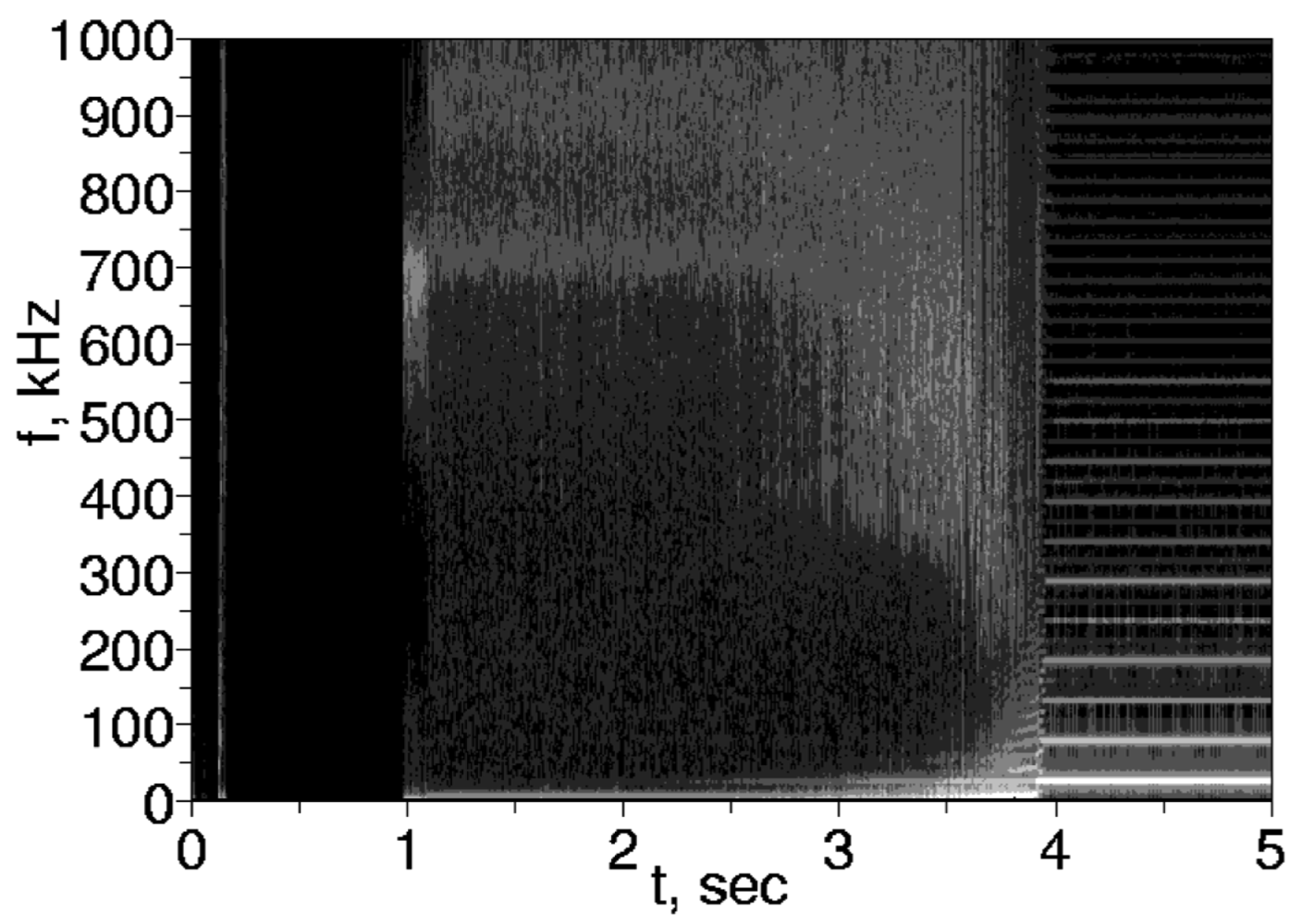
In the current paper a quartz oscillator design without load capacitors is proposed, resulting in 0.12 μW measured power dissipation at a power supply voltage 0.53 V. The schematic of the proposed quartz oscillator is shown in Figure 1. With the two quartz resonators (X1-X2) working in the serial resonance mode and two digital CMOS inverters (M3-M6) in the gain loop, the loop phase is zero and the loop gain is larger than unity for small signals, resulting in the proper conditions for oscillation start-up. Because no additional load capacitors or phase-shifting resistors are used in the oscillator loop, the power dissipation of the oscillator is reduced. The actual startup mechanism is the excitation of the high-frequency (∼1 MHz) RC oscillator mode. In the RC oscillation mode, the quartz crystals function as the AC coupling capacitors. Because of the non-uniform frequency response induced by the higher overtones of the quartz crystals, the oscillations soon become nearly chaotic, gradually injecting power in the fundamental tone of the quartz crystals. As soon as power in the fundamental 32,768 Hz mode exceeds critical threshold, it rapidly intensifies and shuts down the chaotic oscillation. The measured oscillator spectrum during the startup is shown in Figure 2. Worst-case startup time measured was 6 seconds—much faster than could be expected if the only direct excitation of the fundamental tone was from the thermal noise in the ultra-low power oscillator.

Figure 1.
Schematic of the designed real-time clock (RTC).
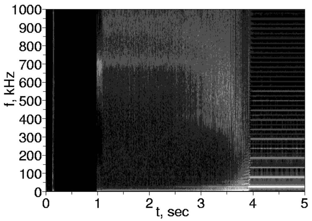
Figure 2.
Output spectrum of the RTC during the startup.
The white line on the bottom-right of the plot is the fundamental frequency (32,768 Hz) of the oscillator. Lines above it are the odd harmonics of the fundamental frequency. Although fundamental frequency line is prominent at 2 s after power-up, it does not shut down the high-frequency oscillations until 3.9 s after power-up.
3. Experimental Results
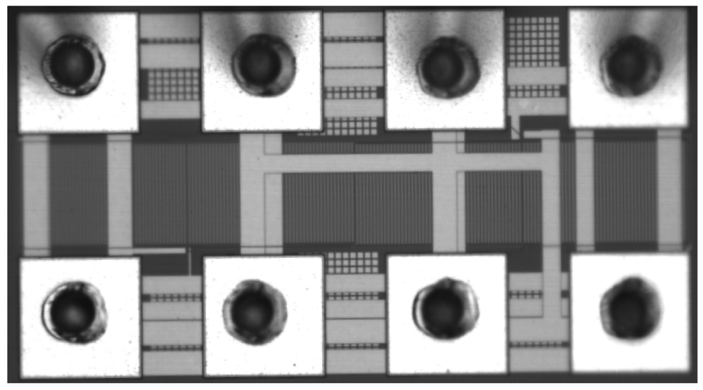
The design of the oscillator was implemented in the LFoundry 0.15 μm mixed-signal CMOS process. Photograph of the fabricated chip is shown in Figure 3. The quartz resonators used were ECS-1X5X discrete crystals. The CMOS IC was packaged in the CERDIP14 package and connected to quartz resonators using a solderless breadboard. The 4 comb-like blocks near the horizontal centerline of Figure 3 is the feedback resistors, and visibility of the most of the other circuitry besides power and ground busses is obstructed by the pads. Oscillator output pads is on the top-right and lower-left corners.
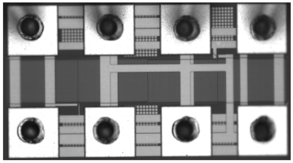
Figure 3.
Chip microphotograph of the designed RTC.
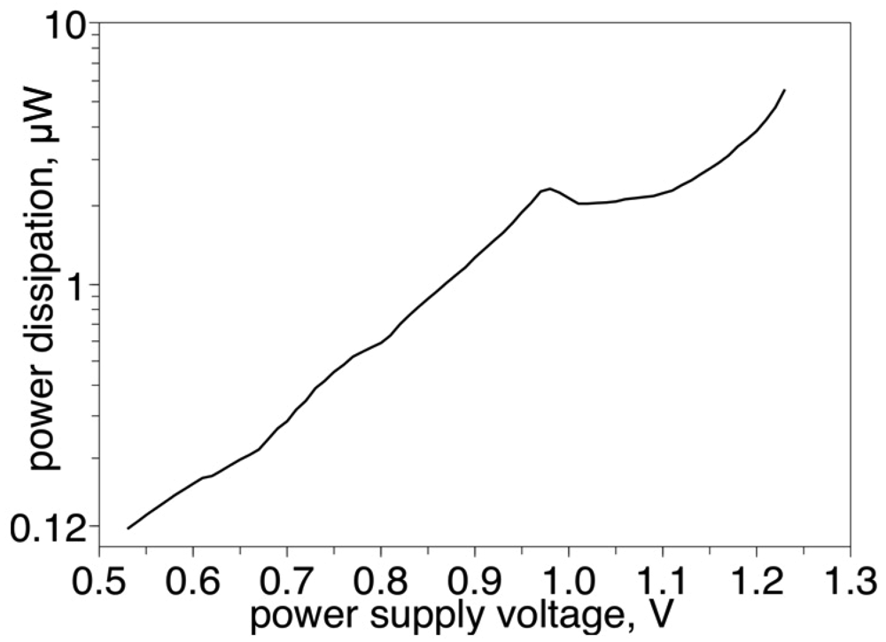
Because no additional load capacitors are used in the oscillator loop, the main contribution to the power dissipation is the charging/discharging of the capacitances of ESD protection diodes (D1–D8). In the current design, the total capacitance of the ESD diodes is 5.6 pF at 1 V power supply voltage. These diodes were designed to withstand 2 kV discharge from the HBM (human body model), to comply with the class 2A ESD sensitivity specifications. Using ESD diodes with the lower capacitance class may decrease power dissipation of the designed circuit even further. The measured power of the fabricated chips is shown in Figure 4.
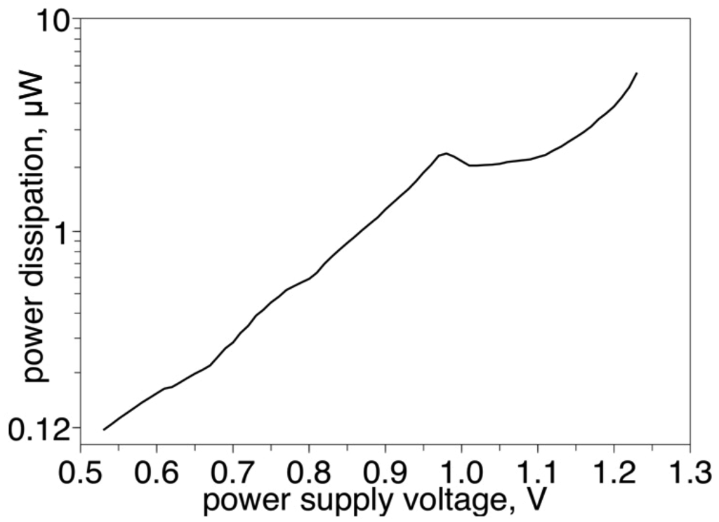
Figure 4.
Power dissipation of the designed RTC.
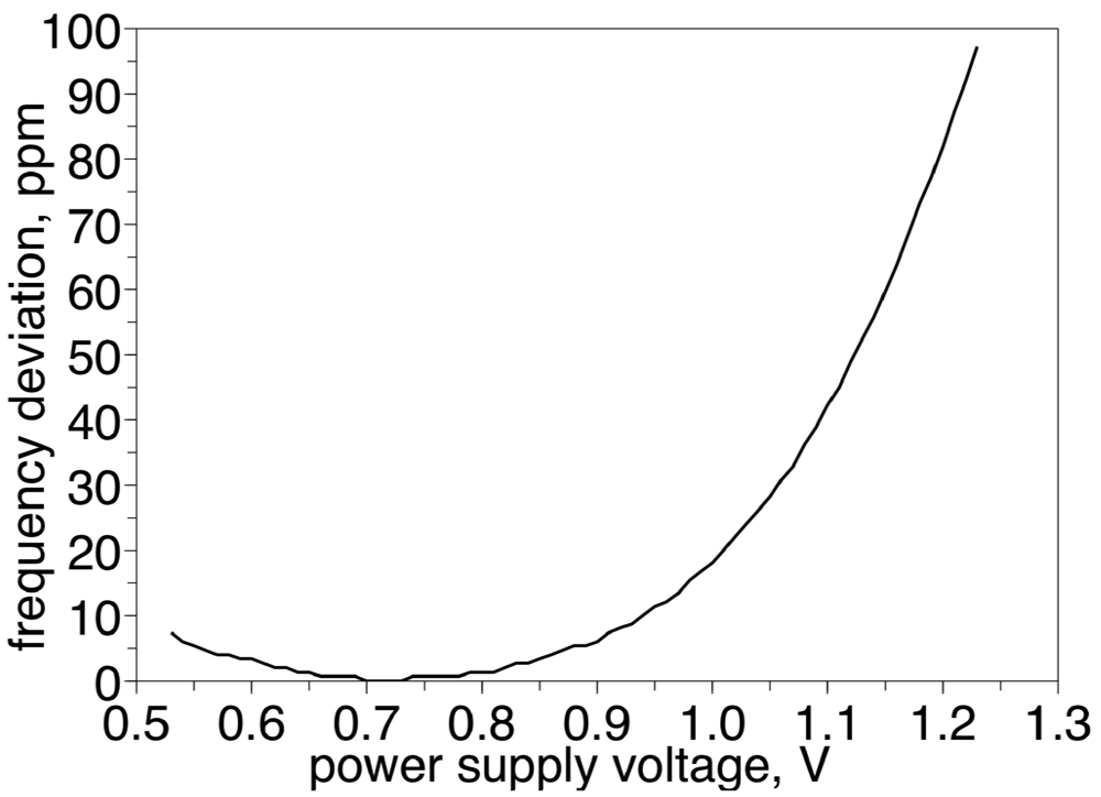
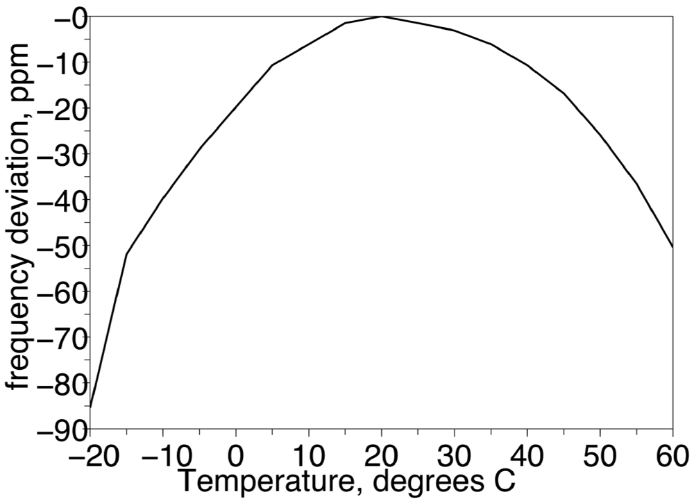
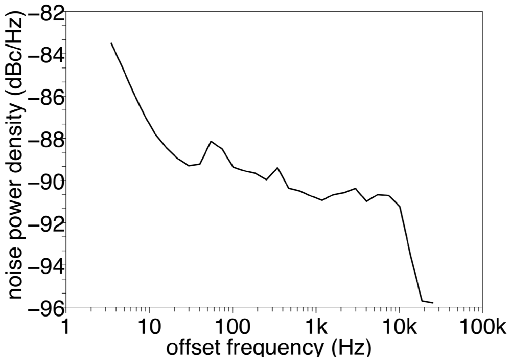
16 MΩ feedback resistors were used to set oscillator frequency-voltage coefficient and to bias inverters to the DC point of the maximal gain. These resistors were fabricated in the high-impedance poly-silicon layer, and have a positive capacitance-voltage coefficient. Because the ESD diodes' capacitance decreases as the power supply voltage increases, with the selected ESD diodes and poly resistors sizes, the frequency-voltage coefficient goes to zero at power supply voltage 0.72 V, as illustrated in Figure 5. The temperature-frequency coefficient of the designed oscillator is mostly determined by the quartz crystal, and exhibits a typical parabolic curve as depicted in Figure 6. The phase noise of the designed oscillator was measured with the spectrum analyzer Agilent N9030A and the measurement results are shown in Figure 7. Phase noise measurement was taken at power supply voltage 0.76 V. At lower power supply voltages measurement of the phase noise was not possible because of the failure of the pad driver to deliver 10 nW of the power to the 50 Ohm load, which is obligatory to lock the spectrum analyzer to the carrier frequency. No deterministic phase jitter associated with the resonant frequency mismatch between the two quartz resonators was found. If such jitter exists, it is expected to produce a spurious tone at 16,384 Hz offset at a level around −106 dBc, which was below the measurement noise floor. In the measured batch of the 10 packaged chips and 40 quartz resonators, the average oscillator frequency was 32,770.40 Hz (73 ppm offset from nominal 32,768 Hz) with standard deviation of the frequency between samples was 5ppm (0.16 Hz).
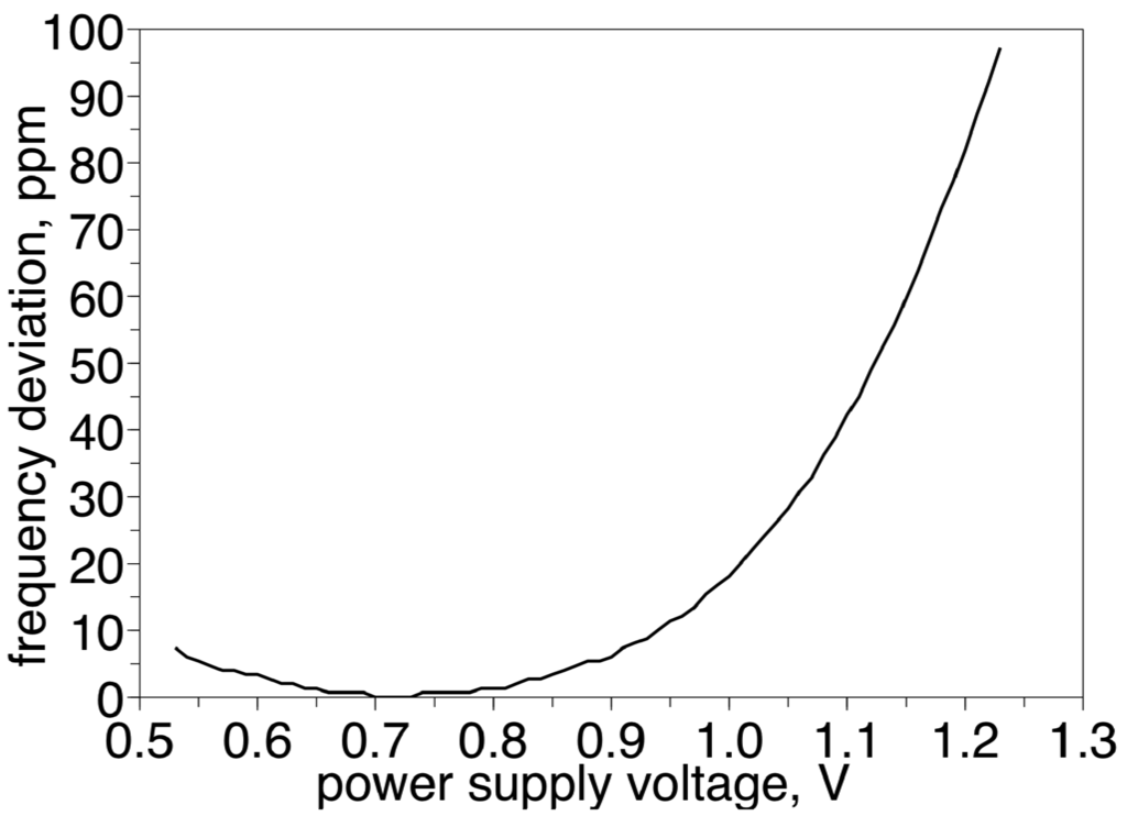
Figure 5.
Frequency of the designed RTC as a function of the power supply voltage.
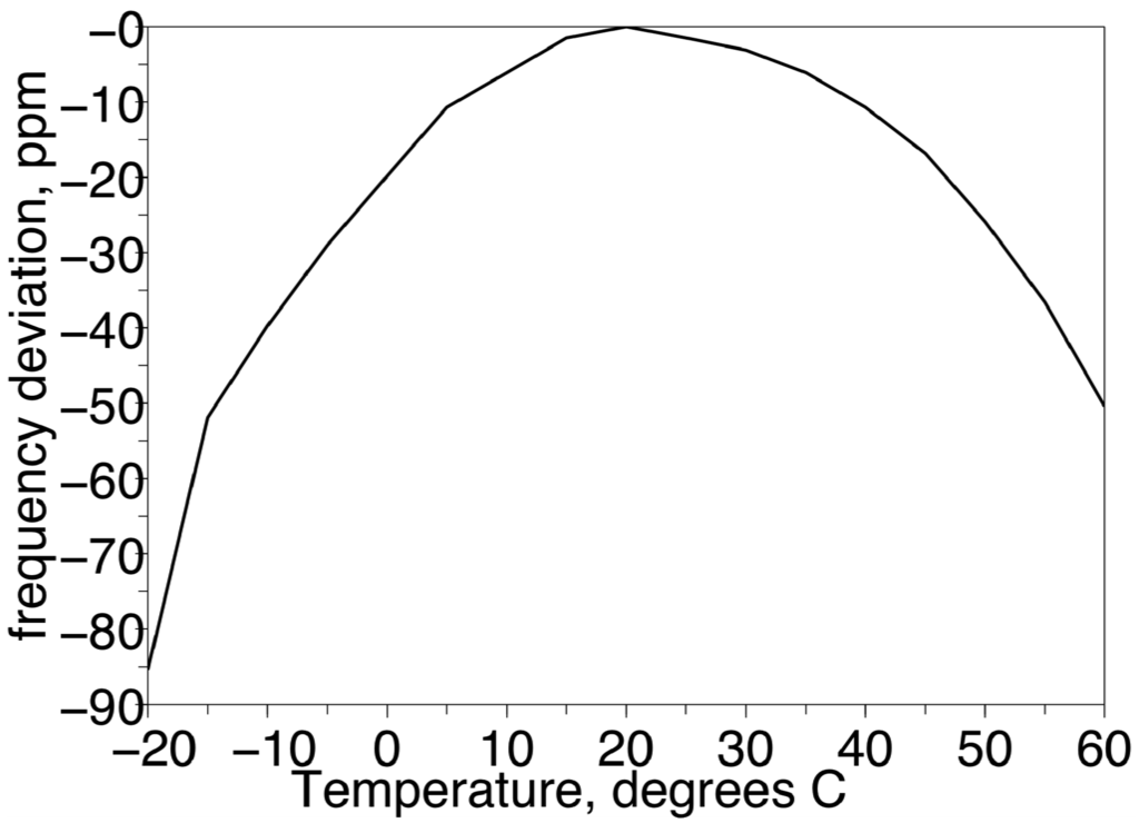
Figure 6.
Frequency of the designed RTC as a function of the temperature.
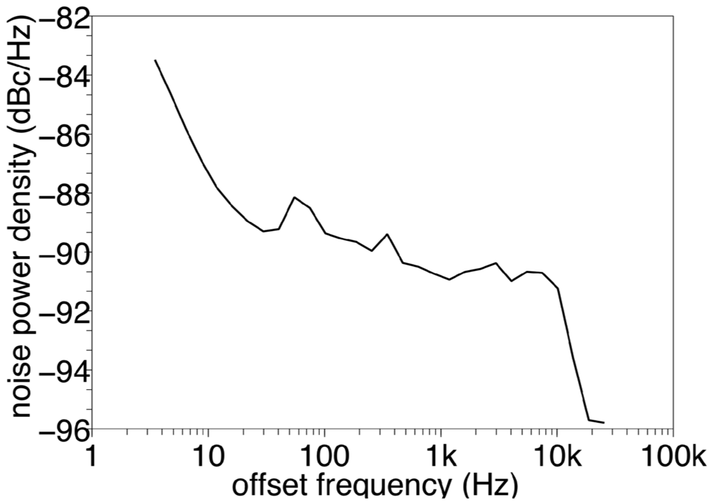
Figure 7.
Measured phase noise of the designed RTC.
4. Conclusion
The designed oscillator is capable of ultra-low power supply (0.53 V) operation compared to the existing models. It also has the lowest power dissipation among the crystal oscillators reported in the literature (see Table 1). Although the accuracy and stability of the designed oscillator complies only to the 100 ppm class, it still may be useful for power-limited, battery powered and energy harvesting systems, where the higher cost of the added second crystal resonator may be compensated by the reduction or elimination of the high-cost lithium battery. The accuracy bottleneck in the current design is the low-cost quartz resonators. In the case of high-performance quartz resonators the accuracy of the oscillator can be improved to the 20 ppm class. The phase noise performance is poor compared to classical crystal oscillators, but better than the integrated electrostatic and piezoelectric systems.

Table 1.
A comparison of the state-of-art low frequency oscillators.
Acknowledgments
This work was partly supported by a VDEC of the University of Tokyo in collaboration with CADENCE Corporation.
References
- Ruffieux, D.; Pliska, A.; Krummenacher, F. Silicon-resonator-based, 3 μA Real-time Clock with 5ppm Frequency Accuracy. Proceedings of the International Solid-State Circuits Conference (ISSCC), San Francisco, CA, USA, 8–12 February 2009; pp. 209–211.
- Roessig, T.A.; Howe, R.T.; Pisano, A.P. Nonlinear Mixing in Surface-micromachined Tuning Fork Oscillators. Proceedings of the 1997 IEEE International Frequency Control Symposium; Institute of Electrical & Electronics Engineers: New York, NY, USA, 1998; pp. 778–782. [Google Scholar]
- Tuantranont, A.; Wisitsora-at, A.; Sritongkham, P.; Jaruwongrungsee, K. A review of monolithic multichannel quartz crystal microbalance: A review. Anal. Chim. Acta 2011, 687, 114–128. [Google Scholar]
- Pantalei, S.; Zampetti, E.; Macagnano, A.; Bearzotti, A.; Venditti, I.; Russo, M.V. Enhanced Sensory properties of a multichannel quartz crystal microbalance coated with polymeric nanobeads. Sensors 2007, 7, 2920–2928. [Google Scholar]
- Epson Toyocom SG-3040LC/JC Quartz Oscillator Datasheet. Available online: http://www.epsontoyocom.co.jp/product/OSC/set01/sg3040lc_jc/index.html (accessed on 10 May 2011).
- Aebischer, D.; Oguey, H.J.; von Kaenel, V.R. A 2.1-MHz crystal oscillator time base with a current consumption under 500 nA. IEEE J. Solid-State Circuits 1997, 32, 999–1005. [Google Scholar]
- Karthaus, U. A differential two-pin crystal oscillator—concept, analysis, and implementation. IEEE Trans. Circuits Syst. 2006, 53, 1073–1077. [Google Scholar]
- Thommen, W. An Improved Low Power Crystal Oscillator. Proceedings of the 25th European Solid-State Circuits Conference (ESSCIRC '99), Duisburg, Germany, 21–23 September 1999; pp. 146–149.
© 2011 by the authors; licensee MDPI, Basel, Switzerland. This article is an open access article distributed under the terms and conditions of the Creative Commons Attribution license (http://creativecommons.org/licenses/by/3.0/).


