Article

Chaos Engineering for Resilient Manufacturing: A Digital Twin Perspective

by
Tim van Erp
1,2,3,*,
Vickie Hohberg
3,
Christoffer Aske Møller Huus
3,
Laura Kristine Stokholm Tiedemann
3 and
Joakim Stokholm Tiedemann
3
1
College of Science and Engineering, Flinders University, GPO Box 2100, Adelaide, SA 5001, Australia
2
College of Business, Creative Arts, Law and Social Sciences, Flinders University, GPO Box 2100, Adelaide, SA 5001, Australia
3
Department of Technology and Innovation, Faculty of Engineering, University of Southern Denmark, Campusvej 55, 5230 Odense, Denmark
*
Author to whom correspondence should be addressed.
Systems 2026, 14(6), 608; https://doi.org/10.3390/systems14060608
Submission received: 27 January 2026 / Revised: 13 April 2026 / Accepted: 24 April 2026 / Published: 26 May 2026

Abstract

Chaos engineering is currently being used by some of the largest software companies in the world to develop IT systems that can withstand turbulent production conditions. This study presents an approach for applying chaos engineering across manufacturing systems to improve system resilience. For this purpose, the proposed chaos twin framework includes a four-step process for the manufacturing and interlinked digital twin system. A case study is discussed based on a material flow simulation. The case study shows the example implementation of the chaos twin framework for improving the resilience of a manufacturing system. The research intends to enhance the field of designing and operating manufacturing systems by demonstrating novel perspectives on applying chaos engineering within the cyberspace. Additionally, the research intends to provide a more industry-oriented guide to facilitate the practical application of chaos engineering within the manufacturing industry.

1. Introduction

1.1. Rationale

Industry 5.0 ecosystems can be characterised by human-centric, resilient, and sustainable value creation [1,2] and are, in addition to the so-called twin, green, and digital transition [3], sometimes described as the future industrial paradigm for supporting the realisation of the United Nations Agenda 2030 [4]. Within the Industry 5.0 concept, system resilience is defined as a key characteristic of manufacturing systems [5,6]. As a method to test how systems respond to stress, chaos engineering is used by some of the largest software companies in the world, such as Netflix, Amazon, Google, Facebook, LinkedIn, and Microsoft [7]. Chaos engineering comprises approaches that aim to experiment with an operational system “[…] to build confidence in the system’s capability to withstand turbulent conditions in production” [8]. Netflix seems to be one of the first movers in chaos engineering when it started developing an initiative named Chaos Monkey [9], which is evidenced to be a quite successful initiative across Netflix [10].
This approach seemed counterintuitive at first, as failures are purposefully injected into a live production network system [11]. An analogy used to describe chaos engineering is to compare it with the purpose of a vaccine: “[…] we inject harm into our system to build an immunity” [12], implying that there will never be immunity to all failures, simply because it is impossible to be aware of all possible failures in a complex system. Even though the application of chaos engineering has a demonstrated track record in the software industry for building resilient production systems, it has hardly been applied to the manufacturing domain, although some authors have started to explore its potential for manufacturing, as described in [13,14].
Against this backdrop, this study aims to investigate how the methodology and principles of chaos engineering can be used to create value in the context of manufacturing systems primarily by improving the resilience of the system and using digital twin technology.

1.2. Theoretical Background

Chaos engineering is “[…] the discipline of experimenting on a system to build confidence in the system’s capability to withstand turbulent conditions in production” [8]. It can be utilised to identify a steady state, which can be characterised as the normal behaviour of the system in operation [8,15]. Subsequently, faults are injected to stress the system and to evaluate the system’s resilience under real operational conditions [15,16]. Chaos engineering can typically be performed in four steps (Table 1).
Poltronieri et al. try to mitigate that chaos engineering can be an expensive practice, with high setup and operations costs, by suggesting using a digital twin of an IT service for chaos engineering [15]. This so-called ChaosTwin allows the conduction of experiments within a safer environment, which can minimise related costs and provide useful feedback at the system design stage [18].

1.3. Research Hypothesis and Research Questions

The underlying main research hypothesis (RH) for the study is:
RH: Chaos engineering in manufacturing systems will only be pursued by manufacturing companies if the consequences of the experimentation have no negative impact on, but adequately reflect, the actual behaviour of the real-world manufacturing system.
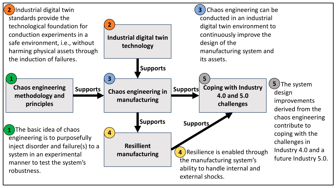
This means resilience is the capacity of a manufacturing system to return to a competitive state “[…] by preparing for, responding to, and recovering from internal or external and known or unknown disturbances” [19]. Currently, emerging industry standards for utilising digital twin technology can support the implementation of chaos engineering completely in cyberspace. The cyberspace allows for safe experimentation without harming physical assets through the intentional induction of failures, disruptions, or other disaster events. Hence, chaos engineering and the learning generated from its application can help manufacturing companies to improve their readiness for Industry 4.0 and Industry 5.0. The context of the research’s main ideas and concepts is summarised in Figure 1.
The following research question (RQ) including sub-research questions (SRQs) are formulated for this study:
RQ: How can chaos engineering principles be applied to create value for the design and operation of manufacturing systems?
  • SRQ1: What are the important process phases for applying chaos engineering in a manufacturing cyberspace?
  • SRQ2: How can the digital twin technology in combination with simulation models support the application of chaos engineering in manufacturing systems?

1.4. Research Methodology

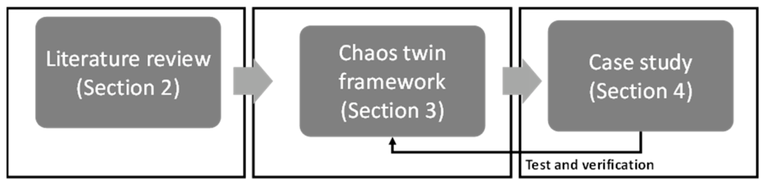
For pursuing RQ and SRQs, the research methodology follows a mostly qualitative research approach, which can be structured into three main phases (Figure 2).
A narrative literature review is used to describe the state-of-the-art for the field of chaos engineering. The literature review (Section 2) serves to present an overview of the current state of academic and industrial research and the application for the scope of this study. It further aims to place the research within literature by highlighting the research gaps.
For framework development (Section 3), the underlying hypothesis is that through the increasing dissemination of digital twins across the manufacturing industry, chaos engineering can be safely executed in a digital twin environment without causing harm to the physical system, i.e., the hardware, such as machine tools. The chaos twin framework provides a process model with four defined steps for the application of chaos engineering. The case study (Section 4) serves as an example implementation of the chaos twin framework for improving the resilience of a simple manufacturing system, which helps to test and verify the chaos twin framework.

2. Literature Review

2.1. Method

The literature review follows a narrative approach covering recent publications within the scope of this study. This scope covers:
  • Digital twins in manufacturing, since chaos engineering for manufacturing will be incorporated into the digital twin which allows the execution of chaos experiments in cyberspace without interfering with the actual hardware of the manufacturing system.
  • Resilience in manufacturing, since resilience is an important target of Industry 4.0/5.0 where chaos engineering is expected to have a large impact.
  • Chaos engineering in manufacturing, since this will be the specific application case for chaos engineering in this study.

2.2. Digital Twins in Manufacturing

For many years, digital twins have been discussed by academics and industry actors as one of the key enabling technologies to support the implementation of the Industry 4.0 paradigm across the manufacturing industry. This leads to the application of more digital twins throughout manufacturing systems [20]. Digital twins are characterised by offering digital artifacts for managing the lifecycle data of manufacturing assets. Manufacturing assets in this sense can be products, machine tools and other manufacturing equipment, software services, production cells and lines, or even whole factories and value networks [21]. The trend of increasingly available digital twins allows for utilising the lifecycle data of connected assets for conducting experiments across the manufacturing system in cyberspace.
Table 2 highlights current studies on the application of digital twin technologies and standardisation trends in a broader manufacturing context. Standardisation trends for an interoperable digital twin are promoted, for example, by the Industrial Digital Twin Association (IDTA) as well as by international standards, i.e., ISO 23247-1:2021 [22], ISO/IEC 20924:2024 [23], and ISO/IEC 30173:2023 [24].
The IDTA seems to be one of the relevant industry-driven organisations currently developing technologies and industry standards for the application of the digital twin across the manufacturing industry, with more than 100 member companies [25]. The key technology promoted by the IDTA is the so-called Asset Administration Shell (AAS), the digital twin in Industry 4.0 and manufacturing [26]. Also, in academic research, the AAS technology is widely known for describing digital twins or aspects of digital twins in manufacturing systems, e.g., as demonstrated by [27,28,29,30].
Table 2. Some relevant studies for digital twins in manufacturing.
StudyFocus on Application or Standardisation
Liu et al. present a more general survey on the current status of implementing digital twins [31].Application: Classification of digital twin implementations covering technologies and features.
He and Bai provide a review of the digital-twin technology supporting sustainable and intelligent manufacturing [32].Application: Intelligent Manufacturing with digital twins allowing intelligent sensing and simulation.
Nee and Ong present a compilation of works on digital twin applications across the industry [33].Application: Compilation of studies which discuss different applications, spanning from systems levels to the level of specific processes and products.
Arm et al. describe the automated design of the AAS standard for implementing the digital twin [34].Standardisation: Introduction of a configuration wizard for AAS creation in Industry 4.0.
Lu et al. discuss the model-based definition of the AAS for manufacturing assets [35]. Standardisation: Introduces the Model-Based Definition (MBD)-assisted digital twin for designing Industry 4.0 production lines based on the AAS standard.
Gregory et al. discuss a model-based systems engineering approach to support the engineering of standardised digital twins [36].Standardisation: Introduction of requirements and functions for developing digital twins while considering relevant ISO, IEC, IEEE standards.
Belfadel et al. propose an open platform design for digital twin standards [37].Standardisation: Introduction of an architecture and digital twin platform aligned with IEC and AAS standards.
The Industrial Internet Consortium Standards Task Group presents the best practice paper on Global Industry Standards for Industrial IoT [38].Standardisation: Provides an overview of global standardisation activities in the context of digital twins in an industry environment.
The Plattform Industry 4.0 and the IDTA present a digital twin reference model based on the AAS standard [39].Standardisation: Highlights the industry standard for digital twins, namely the AAS, in the German Industry 4.0 context.

2.3. Resilience in Manufacturing

Resilience is the capacity of a manufacturing system to return to a competitive state “[…] by preparing for, responding to, and recovering from internal or external and known or unknown disturbances” [19]. Improving and maintaining resilience is an important target for modern manufacturing systems in Industry 4.0/5.0. Academics are discussing different frameworks for this purpose, focusing, for example, on strategies, optimisation, the human operator, and systems engineering (Table 3).
Current frameworks in the field of resilience might support the future application of chaos engineering in the manufacturing domain, as these frameworks enable the modelling and analysis of complex and dynamic manufacturing systems. Especially, analysing and understanding the interrelation of the technical system with the product and product lifecycle, fabrication and assembly processes, organisation, human, value network, business model (following the structure from [46]) and its impact on the system resilience might be essential for manufacturing systems in an increasingly uncertain environment.

2.4. Chaos Engineering in Manufacturing

Chaos Engineering in manufacturing focuses on reducing the impacts of unknown and unimagined failures, disruptions, and disasters, i.e., disturbances, during all lifecycle phases of manufacturing systems. In general, chaos engineering seems rather underexplored in academic literature and industrial practice. Table 4 highlights some relevant studies that discuss the application of chaos engineering for different types of systems. Manufacturing approaches for using chaos engineering as a part of site reliability engineering [47] as well as for supporting resilience [14] are discussed. Other authors describe the application of chaos engineering for cyber-physical, digital twin, service, and critical infrastructure systems. Further studies discuss the implementation of chaos engineering for a variety of systems and system-of-systems. Some of the currently published approaches seem to focus on using chaos engineering for assessment purposes rather than for supporting the synthesis and design phases of systems.

2.5. Research Gap

Specific frameworks for utilising chaos engineering to design and continuously improve manufacturing systems seem to be insufficiently discussed. Doan et al. just published requirements and a process model for the application of chaos engineering in a learning factory environment to reduce the risk of experimentation, while also recommending the use of digital twins as an alternative approach to risk reduction [14]. Hence, the application of chaos engineering within manufacturing systems using the concept of digital twins is yet to be explored in sufficient detail. In the context of chaos engineering and digital twins, the development of a theoretical framework seems to be relevant to provide some initial guidance on implementing chaos engineering across manufacturing systems such as complex Industry 4.0/5.0 factories.
Running chaos experiments by purposely inducing failures in manufacturing systems is time-consuming and costly, and can directly impact the safety, security, and quality of fabrication and assembly processes. As a result, the disadvantages might often outweigh the potential advantages of chaos experimentation. The increasing utilisation of cyber-physical systems with standardised digital twins might become a game changer in the future since digital twin technology allows for experimentation completely in cyberspace and essentially reduces the barriers and potential negative impacts of chaos engineering in manufacturing.

3. Chaos Twin Framework

3.1. Framework Introduction

The chaos twin framework is developed by transferring the chaos engineering idea with its defined principles and process phases from the software to the manufacturing and digital twin domains. Subsequently, the chaos twin framework with its four synthesised process steps is discussed to reflect the specific characteristics and needs of manufacturing systems. Essential theoretical concepts that have been used to develop the framework are:
  • The ChaosTwin [15,18] as inspiration for using a digital twin for chaos engineering and for the name of the framework.
  • The process steps [8,17] (Table 1) are used to derive the chaos engineering process steps for a manufacturing context.
  • The industrial digital twin technology, as developed by [26], with its specific standardised sub-models and as listed under [54]. This technology allows chaos engineering within the cyberspace of manufacturing systems.
  • The resilience engineering framework according to [19] helps to classify the resilience impact of chaos engineering in manufacturing.

3.2. Process Steps

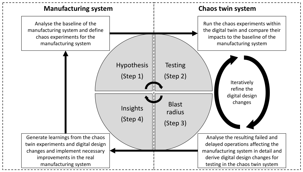
The chaos twin framework’s process is based on the process steps from [8,17]. By utilising a chaos twin for experimentation, it is possible to avoid unnecessary damage to the physical manufacturing system. Figure 3 highlights the chaos twin framework for manufacturing systems.
The implementation of the chaos twin framework across the manufacturing domain requires the design and operation of a digital twin system, which in turn allows chaos experiments in cyberspace to generate learning that can be sufficiently transferred into the real world.
Step 1 “Hypothesis”: The first step of the framework is to define chaos experiments for a given baseline of the manufacturing system. Chaos experiments must be able to reflect failures, disruptions, and disaster events, i.e., disturbances, across the manufacturing system holistically, e.g., by applying the logic in Table 5, which is inspired by the work of [46], for structuring value creation in manufacturing.
A chaos experiment is characterised by a change of a set of variables that intend to cause chaos in the manufacturing system, i.e., by having the potential to lead to failure, disruption, or disaster events. Variable changes might be selected randomly within a realistic limit to reflect the uncertainty of designing and operating a manufacturing system. Further, the definition of chaos experiments is dependent on the resilience phase, i.e., whether the experiment takes place during the anticipation, coping, or adaptation phase as described in Table 6. Variable changes might comprise changing takt times, energy supply to the facilities, number of workers and team composition, equipment failure, or a cyber-attack via different attack vectors.
Step 2 “Testing”: The second step is the design and implementation of the chaos experiment in the digital twin, i.e., the digital environment. By running the chaos experiment, the digital twin functions as the chaos twin of the manufacturing system [15]. The digital twin should follow the Asset Administration Shell standard and related sub-model standards of the Industrial Digital Twin Association [54]. These standards allow for modelling and adequately reflecting the real-world behaviour of the manufacturing system by offering industry-relevant sub-models for composing digital twin systems(-of-systems), as also elaborated by [21]. For example, the loss of a key component supplier can be run as a chaos experiment with a material flow simulation of the manufacturing system. In this case, the material flow simulation represents a specific sub-model standard of the digital twin system. The resulting failed and delayed operations from the chaos experiment, e.g., resulting material defects or inbound logistics delays, are analysed within the simulation and their impact is compared to the baseline of the manufacturing system. For example, the increase in the throughput time of products due to the loss of the key supplier is compared to the baseline throughput time of the system.
Step 3 “Blast radius”: Within the third step, the resulting impacts from the chaos experiments compared to the baseline of the manufacturing system are analysed in more depth. Subsequently, specific design changes are derived and tested within the digital twin. The design changes aim at mitigating the negative impacts from the chaos experiments to the baseline of the manufacturing system. For example, a design change might be to add a new machine tool or to change the layout of the manufacturing system. The design changes are iteratively developed based on a cycle of analysis and synthesis between Step 2 and Step 3. This ensures a continuous refinement of the design changes based on the chaos experiments.
Step 4 “Insights”: The fourth step is to generate learnings from the design changes that have been tested within the chaos twin system. Efficacious improvement measures for the real manufacturing systems are selected, designed, and implemented. The implemented measures should eventually improve the resilience of the real manufacturing system by increasing its capability to cope with chaos while reducing the impact of failure, disruption, or disaster events such as failed and delayed operations.

3.3. Resilience Aspects of Chaos Engineering in Manufacturing

Resilience is a targeted value of a manufacturing system that can be improved through the utilisation of chaos engineering. Resilience can be structured into an anticipation phase, which aims at anticipating and preparing for potential failures, disruptions, and disasters; a coping phase, which foremost aims at reducing the negative impact of an occurring failure, disruption, or disaster; and an adaptation phase, which translates learnings from the failure, disruption, or disaster event into permanent improvements of the manufacturing system [19]. Table 6 highlights the potential impacts of chaos engineering during each of these three phases.

4. Case Study

4.1. Introduction to the Case Study

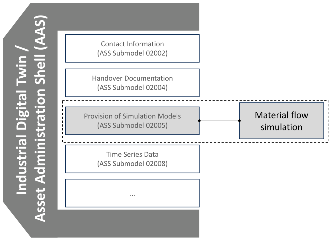
This case study shows how the digital twin technology presented by the IDTA can potentially be used to facilitate chaos engineering. The sub-model standard IDTA 02005 specifies the provision of simulation models for application within the AAS [55]. Thus, the use of a material flow simulation model for this case study seems suitable to demonstrate the efficacy of the chaos engineering framework for testing and verification purposes. Figure 4 shows the idea of the case study and illustrates how the material flow simulation could potentially be embedded as a sub-model, according to the IDTA 02005 standard, into the standardised digital twin technology, namely the AAS. However, as part of this study, the material flow simulation was not implemented into the AAS sub-model standard 02005.
To test and verify the chaos twin framework, the four process steps for working with chaos engineering are exemplarily conducted using a material flow simulation model. The creation of the material flow simulation model itself has been inspired by a real manufacturing case from the Danish industry with a material flow presented in Figure 5. However, the model eventually reflects a fictive case with a focus on managing a fleet of Automated Intelligent Vehicles (AIVs) for the assembly of three product variants S, M, and L. The material flow simulation model is created in Siemens Tecnomatix Plant Simulation v15.1. A description of relevant simulation elements is listed in Table 7.

4.2. Application of the Chaos Twin Framework

4.2.1. Step 1 “Hypothesis”

The baseline of the manufacturing system in the use case is measured based on the key performance indicators (KPIs) listed in Table 8 within the material flow simulation model, i.e., the potential sub-model of the AAS. The baseline serves as the foundation for defining the chaos experiments. Five chaos experiments are defined (Table 9).
Within this case study, the chaos experiments are defined during the anticipation phase of resilience with a focus on the outlined assembly process. Initial chaos experiments can be defined based on an initial risk assessment, e.g., by trying to identify the riskiest parts of the system [14]. However, the majority of chaos experiments should be defined randomly if possible. Consequently, a random selection of parameters for the chaos experiments allows us to identify and test for previously unknown and unimagined failures, disruptions, and disasters and to evaluate their impacts such as for critical and interlinked chains of events. For example, the combined failure of an assembly station and transportation unit might lead to overloading the safety and maintenance department, which then cannot respond on time anymore to other more safety-critical events.

4.2.2. Step 2 “Testing”

The chaos experiments are run in the material flow simulation model of the manufacturing system. The new KPIs are measured for the different chaos experiments as highlighted in Table 10.
The total production time and cycle time increase, while the throughput per day decreases, for the chaos experiments Chaos 2, Chaos 3, Chaos 4, and Chaos 5. For example, the total time for producing the product mix increases from ca. 10 d 9 h to ca. 10 d 13 h for Chaos 2 and Chaos 4 and goes up to ca. 11 d 21 h for Chaos 5 due to the induced failures and disruptions defined in Table 9. Thus, Chaos 2, Chaos 3, Chaos 4, and Chaos 5 lead to negative impacts on the manufacturing system, whereas Chaos 5 seems to have the qualitatively most serious impact on the system in terms of delays. Chaos 1 does not seem to have any negative impacts, as there are no changes to the KPIs compared to the baseline.

4.2.3. Step 3 “Blast Radius”

The negative impact of the chaos experiments is prioritised in terms of its negative impact on the baseline of the manufacturing system. Thus, Chaos 5 is chosen for driving digital design changes, as it results in the biggest negative impact on the lead, throughput and cycle times, and total time for product mix. The digital design change comprises the addition of new assembly stations for either the S and M products (design change 1) or the L products (design change 2). The motivation behind both design changes is to create redundancies in the production capacity for the assembly of the product mix to eventually absorb the increase in assembly times for the products by allowing parallelisation of assembly processes. However, the constraint of only having the possibility to implement one of the design changes reflects the cost constraints often faced by companies and the need to select one out of many investment opportunities.
In Table 11, the impacts compared to the baseline are shown for Chaos 5 after each of these two design changes has been implemented in the simulation. Based on the analysis, design change 2 causes a higher lead time but enables the production of more products and results in the production of the entire product mix approx. one day faster.

4.2.4. Step 4 “Insights”

Learnings from the digital design changes and chaos experiments in the previous step eventually lead to the implementation of an additional assembly station for the L products in the real manufacturing system, i.e., the realisation of design change 2 in the real world. The design change intends to improve the resilience of the system by increasing its robustness to unexpectedly increasing assembly times. Consequently, it helps to mitigate the impact of Chaos 5. Since the impact of the other chaos experiments (Chaos 1 to Chaos 4) is rather limited compared to the impact of Chaos 5, no further design changes are being proposed for the real manufacturing system.

5. Discussion

5.1. Critical Reflections and Limitations

Chaos Engineering in manufacturing focuses on reducing the impacts of unknown and unimagined failures, disruptions, and disasters during all lifecycle phases of manufacturing systems. Uncovering these unimagined, and therefore unknown, disturbances during the design phase, for example, by identifying a production layout design that would not allow the evacuation of personnel in the case of a specific equipment failure, might be today neglected due to the complexity of manufacturing systems and the difficulty of identifying these unlikely but high-impact events, or events that depend on the specific dynamic interplay of complex manufacturing sub-systems such as machine tools, humans, and supply chains.
The case study demonstrates a possible efficacy of the proposed chaos twin framework for improving the system resilience in the specific fictive case. The system’s robustness to cope with potential unforeseen events was improved in the material flow simulation. Eventually, a suitable design solution was found and tested to maintain productivity by reducing the impact of a specific chaos from a 14% increase in total production time for the product mix to only a 4% increase in total production time.
However, the case study does not reflect the application of chaos engineering within a real production or digital twin environment. It showcases a fictive case, which has been implemented in one material flow simulation only and not in a real standardised digital twin setup such as the AAS. Hence, the implementation of the material flow simulation into the AAS sub-model standard 02005 and the realisation of data exchange between different AAS sub-models was not tested. Also, disturbances and connected impacts that would occur during real operations are not fully covered by the simple material flow simulation model, as every model has its limitations and does not reflect real-world behaviour in all its details. In addition to only relying on one material flow simulation case study, the small number of chaos experiments is another limitation of this study. Thus, the study only demonstrates the example implementation of chaos engineering in a well-defined simulation environment and it does not allow to draw conclusions about the general usefulness and validity of the approach for manufacturing systems in combination with digital twin technology.
However, the chaos engineering approach could potentially be useful for application across manufacturing systems if the chaos experiments are limited to the industrial digital twin of the system. The induction of random or unknown disturbances to the actual hardware of a running manufacturing system seems implausible as an option for manufacturers, as it conflicts with manufacturing realities where disturbances often lead to high costs, which would typically outweigh the benefits of such an experiment. In the future, we believe that the material flow simulation model will become embedded in the AAS sub-model 02005 and will be based on time series data, thus reflecting the real operational state of the manufacturing system.
The presented adoption of chaos engineering principles, i.e., the four process steps (Step 1: Defining the steady state, Step 2: Set up a hypothesis, Step 3: Introduce variables that reflect real-world events, Step 4: Verify the outcome), seem to be potentially suitable for realising chaos experiments and learnings within the cyberspace of manufacturing systems. However, the question remains whether future experimentation in industrial digital twins is suitable for deriving conclusions about the actual behaviour of the manufacturing system, since digital twins provide only a model of the real world. Even though industrial digital twin models are based on relevant lifecycle data of real manufacturing assets, some uncertainty regarding the fidelity, calibration, or validation of digital twin models might remain and could negatively impact the usefulness of chaos experiments. Also, the adoption of chaos engineering might raise the question of whether it can adequately cope with the complexity of manufacturing value networks. For example, some value networks might be substantially dependent on conditions that are difficult to measure, such as domain knowledge and experience of key personnel or trust between different stakeholders, and hence cannot be easily modelled via digital twin-based chaos engineering.
A barrier to applying the framework seems to be the current maturity of manufacturing systems in terms of using standardised industrial digital twins. Another implementation barrier may be the setup cost by increasing the level of digitalisation and evolving the digital twin maturity level. However, a relatively high maturity of the digital twin technology might be required, since chaos engineering might be most effective if it has access to the live data of a manufacturing system for defining the experiments.
It is expected that not all manufacturing companies are likely to benefit equally from adapting chaos engineering. Differentiating between the types of manufacturing systems is relevant as the number of potential failures and the associated costs can vary greatly depending on the specific system. Because of relatively high cost of potential disturbances, companies using less flexible manufacturing systems, with, for example, rigid production lines and just-in-time inventory management, might likely benefit from using the chaos engineering method.

5.2. Differentiation of Chaos Engineering in Simulation Models from Scenario Testing with Simulation Models

Testing different manufacturing scenarios within complex simulation models is a commonly used practice in manufacturing engineering. For example, creating different layout and manufacturing process chain variants within a material flow simulation model for testing key performance indicators (KPIs), such as machine utilisation, cycle or throughput times, is often used to verify a manufacturing system design before starting the actual system integration process. Differentiating this commonly used practice from chaos engineering with digital twins therefore seems relevant for providing context about the novelty and relevance of chaos engineering in manufacturing. The main difference between traditional scenario testing using, for example, material flow simulation models and chaos engineering is that chaos engineering induces random disturbances such as failures, disruptions, and disaster events into the model. Consequently, a random selection of parameters for the chaos experiments allows the identification and testing of previously unknown and unimagined disturbances as well as to evaluate their impacts. Traditional scenario testing in simulation models is often based on known parameters and system relations for testing different predefined manufacturing scenarios. However, the differences and commonalities between chaos engineering and scenario testing with simulation models may need to be further investigated to develop a clear and unique value proposition for chaos engineering in manufacturing.

5.3. Research Contributions

The research outcomes create knowledge gains within two main dimensions: (A) the academic community, and (B) manufacturing practitioners of the wider industry community.
(A)
For the academic manufacturing community, the research outcomes intend to enhance the field of designing and operating manufacturing systems by demonstrating new perspectives of applying chaos engineering to improve the resilience of manufacturing systems. More specifically, the outcomes might contribute to the research of improving resilience in manufacturing throughout the anticipation, coping, and adaptation phases of resilience. Consequently, the outcomes can contribute to the theory of engineering design methodologies for resilient manufacturing systems by proposing a new theoretical design process with specific phases.
(B)
For manufacturing practitioners, the study intends to provide a novel industry-oriented guide on how to practically apply chaos engineering to real-life manufacturing systems by using the AAS. This guideline aims to facilitate the practical application of chaos engineering outside of the software industry. Additionally, the research might contribute to creating novel application cases, services, and business models for the implementation of digital twin technology by showing the potential benefits of chaos engineering. The search for and definition of new application cases, services, and business models for digital twins (such as, for example, highlighted in [56]) is an ongoing and relevant task for the industry.
Additionally, Table 12 highlights how chaos engineering might address future Industry 5.0 challenges which require further empirical validation.

5.4. Future Research

Future research should further examine how chaos engineering can be implemented beyond material flow simulations in a complete and mature industrial digital twin system such as the AAS and its sub-models. The efficacious generation of random chaos experiments also seems to be an important future research area. Finding the differences and commonalities between chaos engineering and scenario testing with simulation models is of relevance for future research to develop a clear and unique value proposition for chaos engineering in manufacturing. The utilisation of real-time or near real-time digital twin data for carrying out chaos experiments further seems to be an interesting future research opportunity. This would enable chaos experiments for a live manufacturing system and would help to uncover manufacturing system vulnerabilities continuously. Additionally, future research might explore the potential of applying the chaos twin framework to the Industrial Metaverse as a highly mature implementation of the digital twin. The idea of the Industrial Metaverse is to reflect the real manufacturing system with a high level of detail by interlinking the data streams between the physical manufacturing assets and the digital twin system [59]. Consequently, there might be an opportunity for using the chaos twin framework in combination with the Industrial Metaverse to improve resilience of a manufacturing system. The Industrial Metaverse allows the realisation of a highly detailed digital environment, and thus of a digital model that is quite close to the real world. Running chaos experiments in this model is expected to create results similar to running the same experiments in the real world while being highly cost-effective. Also, potential design changes for improving the resilience can be cost-effectively implemented and tested in the Industrial Metaverse.

6. Conclusions

The research presented an approach, supported by a case study, for applying chaos engineering in manufacturing systems to improve resilience. For this purpose, the chaos twin framework includes a four-step process. The first step of the framework aims to define chaos experiments for a given baseline of the manufacturing system. The second step focuses on the design and implementation of the chaos experiment in the digital twin system. Within the third step, resulting impacts from the chaos experiments are compared to the baseline of the manufacturing system and potential design changes for mitigating the impacts are tested in the digital twin system. Eventually, the fourth step addresses the creation of learnings from the design changes that have been tested within the chaos twin system and their eventual implementation in the real manufacturing system. To verify the chaos twin framework, a case study was discussed based on a material flow simulation model as a potential part of an industrial digital twin sub-model. The case study showed the example implementation of the chaos twin framework for improving the system’s resilience. The research results can potentially serve as a framework for applying chaos engineering in manufacturing systems and as a stepping stone for future academic research and industrial implementation.

Author Contributions

Conceptualisation, T.v.E.; methodology, T.v.E., V.H., C.A.M.H., L.K.S.T. and J.S.T.; software, V.H. and C.A.M.H.; validation, T.v.E., V.H., C.A.M.H., L.K.S.T. and J.S.T.; formal analysis, V.H., C.A.M.H., L.K.S.T. and J.S.T.; investigation, T.v.E., V.H., C.A.M.H., L.K.S.T. and J.S.T.; data curation, V.H., C.A.M.H., L.K.S.T. and J.S.T.; writing—original draft preparation, T.v.E., V.H., C.A.M.H., L.K.S.T. and J.S.T.; writing—review and editing, T.v.E.; visualisation, T.v.E.; supervision, T.v.E.; project administration, T.v.E. All authors have read and agreed to the published version of the manuscript.

Funding

This research received no external funding.

Data Availability Statement

Relevant data generated or analysed during this study are included in this paper.

Acknowledgments

The authors acknowledge the use of Microsoft 365 Copilot (Copilot in Microsoft Word), which is a generative AI tool based on OpenAI’s GPT-5 Large Language Model, to support English-language proofreading and copyediting, specifically spelling, grammar, and consistency. All edits were reviewed and validated by T.v.E., who takes full responsibility for the edits. The authors also would like to acknowledge the anonymous reviewers whose feedback helped us to continuously improve the manuscript.

Conflicts of Interest

We declare the following potential and/or perceived non-financial conflict of interest: The co-authors L.K.S.T. and J.S.T. are married. This relationship did not influence the design, conduct, or reporting of the research. The co-authors L.K.S.T., J.S.T., V.H. and C.A.M.H. conducted this research while they were students at the University of Southern Denmark. Since completing their studies, they have taken up positions in the private sector. However, none of their affiliated companies have had any influence on the design, conduct, analysis, or reporting of the research.

References

  1. Ivanov, D. The Industry 5.0 framework: Viability-based integration of the resilience, sustainability, and human-centricity perspectives. Int. J. Prod. Res. Taylor Fr. J. 2023, 61, 1683–1695. [Google Scholar] [CrossRef]
  2. European Commission: Directorate-General for Research and Innovation, Industry 5.0—Towards a Sustainable, Human-Centric and Resilient European Industry, Publications Office of the European Union. 2021. Available online: https://data.europa.eu/doi/10.2777/308407 (accessed on 14 April 2026).
  3. van Erp, T.; Rytter, N. Design and operations framework for the Twin Transition of manufacturing systems. Adv. Prod. Eng. Manag. 2023, 18, 92–103. [Google Scholar] [CrossRef]
  4. United Nations. Transforming Our World: The 2030 Agenda for Sustainable Development, United Nations. 2015. Available online: https://sdgs.un.org/publications/transforming-our-world-2030-agenda-sustainable-development-17981 (accessed on 14 April 2026).
  5. Aheleroff, S.; Huang, H.; Xu, X.; Zhong, R.Y. Toward sustainability and resilience with Industry 4.0 and Industry 5.0. Front. Manuf. Technol. 2022, 2, 951643. [Google Scholar] [CrossRef]
  6. Leng, J.; Zhong, Y.; Lin, Z.; Xu, K.; Mourtzis, D.; Zhou, X.; Zheng, P.; Liu, Q.; Zhao, J.L.; Shen, W. Towards resilience in Industry 5.0: A decentralized autonomous manufacturing paradigm. J. Manuf. Syst. 2023, 71, 95–114. [Google Scholar] [CrossRef]
  7. Gremlin Inc. Chaos Engineering: The History, Principles, and Practice. 2023. Available online: https://www.gremlin.com/community/tutorials/chaos-engineering-the-history-principles-and-practice/ (accessed on 14 April 2026).
  8. Principles of Chaos Engineering. 2019. Available online: https://principlesofchaos.org/ (accessed on 14 April 2026).
  9. Izrailevsky, Y.; Tseitlin, A. The Netflix Simian Army, Netflix Technology Blog. 2011. Available online: https://netflixtechblog.com/the-netflix-simian-army-16e57fbab116 (accessed on 14 April 2026).
  10. Basiri, A.; Behnam, N.; de Rooij, R.; Hochstein, L.; Kosewski, L.; Reynolds, J.; Rosenthal, C. Chaos Engineering. IEEE Softw. 2016, 33, 35–41. [Google Scholar] [CrossRef]
  11. Chang, M.A.; Tschaen, B.; Benson, T.; Vanbever, L. Chaos Monkey: Increasing SDN Reliability through Systematic Network Destruction. In Proceedings of the 2015 ACM Conference on Special Interest Group on Data Communication, London, UK, 17–21 August 2015; pp. 371–372. [Google Scholar] [CrossRef]
  12. Andrus, K. The Evolution of Chaos, O’Reilly. YouTube. Video. 2018. Available online: https://www.youtube.com/watch?v=hRwfLEc-0p4 (accessed on 14 April 2026).
  13. Konstantinou, C.; Stergiopoulos, G.; Parvania, M.; Esteves-Verissimo, P. Chaos Engineering for Enhanced Resilience of Cyber-Physical Systems. In 2021 Resilience Week (RWS); IEEE: Piscataway, NJ, USA, 2021; pp. 1–10. [Google Scholar] [CrossRef]
  14. Doan, A.M.A.; Meldt, L.; Bokemüller, T.; Pohl, N.; Metternich, J.; Weigold, M. Requirement analysis and approach for Chaos Engineering in industrial production. CIRP J. Manuf. Sci. Technol. 2026, 67, 1–14. [Google Scholar] [CrossRef]
  15. Poltronieri, F.; Tortonesi, M.; Stefanelli, C. Chaostwin: A chaos engineering and digital twin approach for the design of resilient IT services. In Proceedings of the 17th International Conference on Network and Service Management (CNSM), Izmir, Turkey, 25–29 October 2021; IEEE: Piscataway, NJ, USA, 2021; pp. 234–238. Available online: https://dl.ifip.org/db/conf/cnsm/cnsm2021/1570725069.pdf (accessed on 14 April 2026).
  16. Jernberg, H.; Runeson, P.; Engström, E. Getting Started with Chaos Engineering-design of an implementation framework in practice. In Proceedings of the 14th ACM/IEEE International Symposium on Empirical Software Engineering and Measurement (ESEM), Bari, Italy, 5–9 October 2020; pp. 1–10. [Google Scholar] [CrossRef]
  17. Gunja, S. What Is Chaos Engineering? Dynatrace. 2023. Available online: https://www.dynatrace.com/news/blog/what-is-chaos-engineering/ (accessed on 14 April 2026).
  18. Poltronieri, F.; Tortonesi, M.; Stefanelli, C. A chaos engineering approach for improving the resiliency of IT services configurations. In Proceedings of the NOMS 2022-2022 IEEE/IFIP Network Operations and Management Symposium, Budapest, Hungary, 25–29 April 2022; IEEE: Piscataway, NJ, USA, 2022; pp. 1–6. [Google Scholar] [CrossRef]
  19. Neumann, K.; van Erp, T.; Steinhöfel, E.; Sieckmann, F.; Kohl, H. Patterns for resilient value creation: Perspective of the German electrical industry during the COVID-19 pandemic. Sustainability 2021, 13, 6090. [Google Scholar] [CrossRef]
  20. Hasan, M. Digital Twin Market: Analyzing Growth and Emerging Trends. IOT Analytics. 2023. Available online: https://iot-analytics.com/digital-twin-market-analyzing-growth-emerging-trends/ (accessed on 14 April 2026).
  21. van Erp, T.; Davidsen, E.E.; Grondahl, O.W.; Petersen, A.N. A factory planning and design framework for integrating the Digital Twin in Industry 4.0. In Proceedings of the 27th International Conference on Emerging Technologies and Factory Automation (ETFA), Stuttgart, Germany, 6–9 September 2022; IEEE: Piscataway, NJ, USA, 2022; pp. 1–8. [Google Scholar] [CrossRef]
  22. ISO 23247-1:2021; Digital Twin Framework for Manufacturing. International Organisation for Standardisation (ISO): Geneva, Switzerland, 2021. Available online: https://www.iso.org/standard/75066.html (accessed on 14 April 2026).
  23. ISO/IEC 20924:2024; Internet of Things (IoT) and Digital Twin—Vocabulary. International Organisation for Standardisation (ISO) and International Electrotechnical Commission (IEC): Geneva, Switzerland, 2024. Available online: https://www.iso.org/standard/88799.html (accessed on 14 April 2026).
  24. ISO/IEC 30173:2023; Digital Twin—Concepts and Terminology. International Organisation for Standardisation (ISO) and International Electrotechnical Commission (IEC): Geneva, Switzerland, 2023. Available online: https://www.iso.org/standard/81442.html (accessed on 14 April 2026).
  25. Industrial Digital Twin Association. Who’s Who—IDTA Members, Industrial Digital Twin Association (IDTA). Available online: https://industrialdigitaltwin.org/en/about-idta/members-idta (accessed on 14 April 2026).
  26. Industrial Digital Twin Association. IDTA—Working Together to Promote the Digital Twin, Industrial Digital Twin Association (IDTA). Available online: https://industrialdigitaltwin.org/en/ (accessed on 14 April 2026).
  27. JRahal, J.R.; Schwarz, A.; Sahelices, B.; Weis, R.; Antón, S.D. The asset administration shell as enabler for predictive maintenance: A review. J. Intell. Manuf. 2025, 36, 19–33. [Google Scholar] [CrossRef]
  28. Ye, X.; Yu, M.; Song, W.S.; Hong, S.H. An Asset Administration Shell Method for Data Exchange Between Manufacturing Software Applications. IEEE Access 2021, 9, 144171–144178. [Google Scholar] [CrossRef]
  29. Ye, X.; Song, W.S.; Hong, S.H.; Kim, Y.C.; Yoo, N.H. Toward Data Interoperability of Enterprise and Control Applications via the Industry 4.0 Asset Administration Shell. IEEE Access 2022, 10, 35795–35803. [Google Scholar] [CrossRef]
  30. Quadrini, W.; Cimino, C.; Abdel-Aty, T.A.; Fumagalli, L.; Rovere, D. Asset Administration Shell as an interoperable enabler of Industry 4.0 software architectures: A case study. Procedia Comput. Sci. 2023, 217, 1794–1802. [Google Scholar] [CrossRef]
  31. Liu, Y.K.; Ong, S.K.; Nee, A.Y.C. State-of-the-art survey on digital twin implementations. Adv. Manuf. 2022, 10, 1–23. [Google Scholar] [CrossRef]
  32. He, B.; Bai, K.-J. Digital twin-based sustainable intelligent manufacturing: A review. Adv. Manuf. 2021, 9, 1–21. [Google Scholar] [CrossRef]
  33. Nee, A.Y.C.; Ong, S.K. Special Issue on Digital Twins in Industry. Appl. Sci. 2021, 11, 6437. [Google Scholar] [CrossRef]
  34. Arm, J.; Benesl, T.; Marcon, P.; Bradac, Z.; Schröder, T.; Belyaev, A.; Werner, T.; Braun, V.; Kamensky, P.; Zezulka, F.; et al. Automated design and integration of Asset Administration Shells in components of Industry 4.0. Sensors 2021, 21, 2004. [Google Scholar] [CrossRef]
  35. Lu, Q.; Li, M.; Zhu, D. Model-based definition-assisted asset administration shell as enabler for smart production line. Int. J. Comput. Integr. Manuf. 2025, 38, 1560–1576. [Google Scholar] [CrossRef]
  36. Gregory, C.; Mbolamananamalala, R.; Rabah, S.; Chapurlat, V. Model Based Systems Engineering applied to Digital Twin engineering: Why and how to? IFAC-PapersOnLine 2024, 58, 157–162. [Google Scholar] [CrossRef]
  37. Belfadel, A.; Creff, S.; Hamida, A.B. Advancing Industrial Digital Twins: Towards an Open Platform Aligned with Standards. In Proceedings of the 21st International Conference on Product Lifecycle Management, Bangkok, Thailand, 7–10 July 2024; Springer: Berlin/Heidelberg, Germany, 2025. [Google Scholar] [CrossRef]
  38. Industrial Internet Consortium. Global Standards for Industrial IoT. Available online: https://www.iiconsortium.org/pdf/IIC_Global_Standards_Strategy_Whitepaper.pdf (accessed on 14 April 2026).
  39. Plattform Industrie 4.0, Digital Twin Reference Model and Standardization to Realize a Sustainable Industry. Available online: https://www.plattform-i40.de/IP/Redaktion/EN/Downloads/Publikation/202404_Digital_twin_sustainable_industry.html (accessed on 14 April 2026).
  40. El-Halwagi, M.M.; Sengupta, D.; Pistikopoulos, E.N.; Sammons, J.; Eljack, F.; Kazi, M.-K. Disaster-resilient design of manufacturing facilities through process integration: Principal strategies, perspectives, and research challenges. Front. Sustain. 2020, 1, 595961. [Google Scholar] [CrossRef]
  41. Feng, Q.; Hai, X.; Liu, M.; Yang, D.; Wang, Z.; Ren, Y.; Sun, B.; Cai, B. Time-based resilience metric for smart manufacturing systems and optimization method with dual-strategy recovery. J. Manuf. Syst. 2022, 65, 486–497. [Google Scholar] [CrossRef]
  42. Romero, D.; Stahre, J. Towards the Resilient Operator 5.0: The Future of Work in Smart Resilient Manufacturing Systems. Procedia CIRP 2021, 104, 1089–1094. [Google Scholar] [CrossRef]
  43. Zhang, C.; Tao, F.; Qi, Q.; Cheng, Y.; Cheng, J.; Wang, B.; Nee, A.Y.C. Digital twin-based shop-floor reconfiguration design for uncertainty management. Int. J. Prod. Res. 2025, 1–25. [Google Scholar] [CrossRef]
  44. Mousavi, B.A.; Heavey, C.; Azzouz, R.; Ehm, H.; Millauer, C.; Knobloch, R. Use of Model-Based System Engineering methodology and tools for disruption analysis of supply chains: A case in semiconductor manufacturing. J. Ind. Inf. Integr. 2022, 28, 100335. [Google Scholar] [CrossRef]
  45. Hossain, N.U.I.; Fazio, S.A.; Lawrence, J.-M.; Gonzalez, E.D.S.; Jaradat, R.; Alvarado, M.S. Role of systems engineering attributes in enhancing supply chain resilience: Healthcare in context of COVID-19 pandemic. Heliyon 2022, 8, e09592. [Google Scholar] [CrossRef]
  46. van Erp, T.; Gładysz, B. Quantum technologies in manufacturing systems: Perspectives for application and sustainable development. Procedia CIRP 2022, 107, 1120–1125. [Google Scholar] [CrossRef]
  47. Dave, D.M. Impact of Site Reliability Engineering on Manufacturing Operations: Improving Efficiency and Reducing Downtime. Int. J. Sci. Res. Publ. 2023, 13, 136–139. [Google Scholar] [CrossRef]
  48. Kalka, W.; Szydlo, T. μ Chaos: Moving Chaos Engineering to IoT Devices. In Proceedings of the International Conference on Computational Science, Malaga, Spain, 2–4 July 2024; Springer Nature: Cham, Switzerland, 2024; pp. 239–254. [Google Scholar] [CrossRef]
  49. Fogli, M.; Giannelli, C.; Poltronieri, F.; Stefanelli, C.; Tortonesi, M. Chaos engineering for resilience assessment of digital twins. IEEE Trans. Ind. Inform. 2023, 20, 1134–1143. [Google Scholar] [CrossRef]
  50. Akuthota, A. Chaos Engineering for Microservices; St. Cloud State University: St. Cloud, MN, USA, 2023; Available online: https://repository.stcloudstate.edu/cgi/viewcontent.cgi?article=1053&context=csit_etds (accessed on 14 April 2026).
  51. Dedousis, P.; Stergiopoulos, G.; Arampatzis, G.; Gritzalis, D. Enhancing Operational Resilience of Critical Infrastructure Processes Through Chaos Engineering. IEEE Access 2023, 11, 106172–106189. [Google Scholar] [CrossRef]
  52. Naqvi, M.A.; Malik, S.; Astekin, M.; Moonen, L. On evaluating self-adaptive and self-healing systems using chaos engineering. In Proceedings of the International Conference on Autonomic Computing and Self-Organizing Systems (ACSOS), Virtual, 19–23 September 2022; IEEE: Piscataway, NJ, USA, 2022; pp. 1–10. [Google Scholar] [CrossRef]
  53. Bailey, T.; Marchione, P.; Swartz, P.; Salih, R.; Clark, M.R.; Denz, R. Measuring resiliency of system of systems using chaos engineering experiments. In Disruptive Technologies in Information Sciences VI; SPIE: Bellingham, WA, USA, 2022; Volume 12117, pp. 20–32. [Google Scholar] [CrossRef]
  54. Industrial Digital Twin Association. AAS Submodel Templates, Industrial Digital Twin Association (IDTA). Available online: https://industrialdigitaltwin.org/content-hub/teilmodelle (accessed on 14 April 2026).
  55. Industrial Digital Twin Association. IDTA 02005-1-0 Provision of Simulation Models, Industrial Digital Twin Association (IDTA). Available online: https://industrialdigitaltwin.org/en/wp-content/uploads/sites/2/2023/01/IDTA-02005-1-0_Submodel_ProvisionOfSimulationModels.pdf (accessed on 14 April 2026).
  56. Industrial Digital Twin Association. Use Cases—The Digital Twin in Practice, Industrial Digital Twin Association (IDTA). Available online: https://industrialdigitaltwin.org/en/use-cases (accessed on 14 April 2026).
  57. Fries, C.; Fechter, M.; Ranke, D.; Trierweiler, M.; Al Assadi, A.; Foith-Förster, P.; Wiendahl, H.-H.; Bauernhansl, T. Fluid Manufacturing Systems (FLMS) A Novel Approach for Versatility in Production. In Advances in Automotive Production Technology—Theory and Application, ARENA2036; Springer: Berlin/Heidelberg, Germany, 2021; pp. 37–44. [Google Scholar] [CrossRef]
  58. Chertow, M.R. Uncovering industrial symbiosis. J. Ind. Ecol. 2007, 11, 11–30. [Google Scholar] [CrossRef]
  59. Marko, A.; Plass, C.; Kuttner, D.; Laß, D.; Bashiri, E.; Barnstedt, E.; Piller, F.; Heinrich, H.; Gayko, J.; Wirth, J.; et al. Perspectives on the Industrial Metaverse, Plattform Industrie 4.0. Available online: https://www.plattform-i40.de/IP/Redaktion/EN/Downloads/Publikation/Industrial_Metaverse.pdf (accessed on 14 April 2026).
Figure 1. Logical context diagram of the research’s main ideas and concepts.
Systems 14 00608 g001
Figure 2. Three-phase research approach.
Systems 14 00608 g002
Figure 3. Chaos twin framework for manufacturing systems.
Systems 14 00608 g003
Figure 4. Theoretical idea for linking material flow simulation and the AAS.
Systems 14 00608 g004
Figure 5. Processes of material flow.
Systems 14 00608 g005
Table 1. Steps for experimentation in chaos engineering.
StepFollowing the Idea from [17]Following the Idea from [8]
1HypothesisDefine the steady state
2TestingDefine the hypothesis
3Blast RadiusIntroduces variables
4InsightsDisprove hypothesis
Table 3. Some relevant studies for resilience in manufacturing.
StudyFocus of Frameworks
Neumann et al. discuss a framework for supporting resilience in the electrical manufacturing industry [19]. Strategies: 110 resilience patterns for supporting value creation
El-Halwagi et al. propose a framework for the disaster-resilient design of manufacturing facilities by using process integration [40]. Strategies: 12 principal strategies for disaster-resilient design
Feng et al. present a time-based resilience metric for smart manufacturing systems [41].Optimisation: Time-based resilience metric and solution framework in the context of job shop scheduling.
Romero and Stahre propose a framework for the resilient operator in Industry 5.0 [42].Human: Operator 5.0 concept with humans to support system resilience.
Zhang et al. present uncertainty management for the shopfloor based on digital twin technology [43].Strategy and optimisation: Reconfiguration design method for shopfloors and based on digital twins with 16 steps and four phases.
Mousavi et al. discuss a model-based systems engineering (MBSE) framework for the disruption analysis of supply chains [44]. Systems Engineering: Application of MBSE methodology to disruption management of a supply chain and application of MBSE tools for problem definition.
Hossain et al. discuss the role of systems engineering attributes in enhancing supply chain resilience [45].Systems Engineering: Conceptual model for supply chain resilience for four phases of resilience.
Table 4. Some relevant studies for chaos engineering in manufacturing.
StudyFocus of Application
Doan et al. derive requirements and show an approach for applying chaos engineering to improve the resilience of manufacturing systems [14]. Manufacturing Systems
Dave discusses a chaos engineering platform as a part of Site Reliability Engineering to improve efficiency and downtime in manufacturing operations [47].Manufacturing System
Konstantinou et al. discuss the use of chaos engineering for supporting resilience in cyber-physical systems [13].Cyber-physical system
Kalka and Szydlo present a chaos engineering tool for IoT devices to test types of failures and failure scenarios [48].Cyber-physical system
Fogli et al. describe chaos engineering for resilience assessment of digital twins [49].Digital twin system
Poltronieri et al. published chaos engineering and chaos twin approaches for improving resilience in IT services [15,18].Service system
Akuthota outlines the application perspective of chaos engineering for microservices [50]. Service system
Dedousis et al. discuss the support of operational resilience of critical infrastructure using chaos engineering [51].Critical infrastructure system
Naqvi at el. highlight the evaluation of self-adaptive and self-healing capabilities of systems using chaos engineering [52].Variety of different systems
Baily et al. present a chaos engineering approach for measuring resilience across system-of-systems [53].System-of-Systems
Table 5. Logical structure for defining events for chaos experiments.
Value Creation DomainsEvents
Failures (Fl)Disruptions (Dp)Disasters (Ds)
Failures are events with small-scale negative impacts limited to a sub-system or domain level.Disruptions are events with medium-scale negative impacts limited to the system level including multiple sub-systems or domains.Disasters are events with large-scale negative impacts beyond the system level including impacts across multiple other systems.
1. Product and Product LifecycleFl11, Fl12, …, Fl1nDp11, Dp12, …, Dp1nDs11, Ds12, …, Ds1n
2. Fabrication and assembly processesFl21, Fl22, …, Fl2nDp21, Dp22, …, Dp2nDs21, Ds22, …, Ds2n
3. OrganisationFl31, Fl32, …, Fl3nDp31, Dp32, …, Dp3nDs31, Ds32, …, Ds3n
4. HumanFl41, Fl42, …, Fl4nDp41, Dp42, …, Dp4nDs41, Ds42, …, Ds4n
5. Value networkFl51, Fl52, …, F5nDp51, Dp52, …, Dp5nDs51, Ds52, …, Ds5n
6. Business modelFl61, Fl62, …, F6nDp61, Dp62, …, Dp6nDs61, Ds62, …, Dp6n
Table 6. Potential impacts of chaos engineering during the three resilience phases.
Resilience PhaseThe Potential Impact of Chaos Engineering
Anticipation phase (before the disturbance event occurs)
  • Chaos engineering can support the anticipation of potential failure, disruption, and disaster events throughout the manufacturing system by randomly defining and running chaos experiments to test the system’s robustness for these unforeseen events.
  • Chaos engineering can support this phase by defining and running chaos experiments in a more targeted manner on the riskiest part of the business model.
  • The overarching goal is to develop an understanding of the robustness of the manufacturing system with its important drivers and barriers as well as their interdependencies and improve the system’s flexibility.
Coping phase (during an active disturbance event)
  • During the occurrence of a failure, disruption, or disaster event, chaos engineering can help to mimic the disaster within cyberspace, i.e., the digital twin, through accordingly defined and executed chaos experiments.
  • These chaos experiments help to understand the implications of the failure, disruption, or disaster event across the manufacturing system much more quickly if the digital twin reflects the real-world behaviour sufficiently.
  • Understanding the implications subsequently fosters the development and implementation of suitable coping strategies for the manufacturing system to counter the failure, disruption, or disaster event.
Adaptation phase (after the occurrence of the disturbance event)
  • After the failure, disruption, or disaster event occurred, chaos engineering can be used to define and run chaos experiments similar in scope and impact to the original failure, disruption, or disaster event.
  • The experiments can be slightly varied, and potentially, machine learning algorithms can learn what an ideal future response of the manufacturing system to this type of failure, disruption, or disaster event would be.
  • Eventually, the design of the manufacturing system can be adapted to enable this identified ideal future response.
  • Moreover, the learnings from the chaos experiments during the coping phase can be used to adapt the business model of the manufacturer to actively benefit from or exploit the impacts of the failure, disruption, and disaster events in such a manner that competitive advantages for the manufacturer can be realised.
Table 7. Simulation elements.
Element No.NameDescription of the Area
1SourceDistributes product demand at a given rate and quantity, i.e. creates orders for product variants S, M, L.
2Kitting areaTwo stations (Kitting 1 and 2) kit the orders received from the source.
3Worker pool and brokerIn this simulation, the “workers” element is used to represent Automated Intelligent Vehicles (AIVs), as they can move freely. The worker pool represents the charging area for the AIVs. The broker distributes the number of AIVs and their speed.
4Assembly area of product variants S and MFour stations (Delivery 1 to 4) can be used to unload the kitted pallets. A conveyor belt moves the kitted pallets from each of these stations to a subsequent, dedicated assembly station(Assembly 1 to 4). A conveyor belt moves the assembled product from the assembly stations to two possible pick-up places (Pick-up 1 and 2).
5Assembly area of product variant LTwo stations (Delivery 5 and 6) are used to unload the kitted pallets. A conveyor belt moves the kitted pallets from each of these stations to a subsequent, dedicated assembly station (Assembly 5 and 6). A conveyor belt moves the assembled product from the assembly stations to a pick-up place (Pick-up 3)
6Drain for product variants S and product MThe drain is the delivery station (Delivery 7) for the assembled products (variants S and M).
7Drain for product variant LThe drain is the delivery station (Delivery 8) for the assembled products (variant L).
Table 8. Data collected on baseline performance.
Key Performance IndicatorsBaseline
Lead time mean for all products (hh:mm:ss)03:58:46
Throughput per day mean for all products (pcs.)17
Cycle time mean for all products (hh:mm:ss)01:46:32
Kitting resources mean working1%
Kitting resources mean waiting32%
Kitting resources mean failed0%
Kitting resources mean blocked67%
Transport units mean transporting37%
Transport units mean en route to job11%
Transport units mean waiting53%
Transport units mean failed0%
Assembly stations mean working92%
Assembly stations mean waiting8%
Assembly stations mean failed0%
Assembly stations mean blocked0%
Total time for product mix10:09:42
Table 9. Chaos experiments.
Chaos IDWhat?When?How?Reasoning/
Comments
1The kitting area kits the wrong subassembly5% of total processing timeIntroducing a constant failure for both kitting stations.The current kitting process is manual; thus, the system may be vulnerable to varying kitting errors
2The product mix is changedThrough the whole material flow simulationExchange of the production volume of the two products with the highest volume with the two products with the lowest volumeMarket changes may change the product mix of the manufacturing system
3One transport unit failsThroughout the whole simulationTake one transport unit out of the simulation
4Failures in assembly stations in the assembly area of product variants S and M10% of total processing timeIntroducing a constant failure to the assembly stations for product variants S and M. Machinery may wear down, or the employment of new employees requires training period(s)
5All assembly times increaseThroughout the whole simulationAll assembly times are increased by 10 minPackaging changes for all products, new features are added to the assembly, or more difficult assembly process steps are introduced.
Table 10. Comparison of the baseline KPIs with the KPIs resulting from the chaos experiments.
Key Performance IndicatorsBaselineChaos 1Chaos 2Chaos 3Chaos 4Chaos 5
Lead time mean for all products (hh:mm:ss)03:58:4603:58:4604:20:5302:20:3604:26:1505:02:56
Throughput per day mean for all products (pcs.)171716.816.716.814.9
Cycle time mean for all products (hh:mm:ss)01:46:3201:46:2501:48:3901:48:1601:48:5902:02:14
Kitting resources mean working1%1%1%1%1%1%
Kitting resources mean waiting32%32%33%32%33%33%
Kitting resources mean failed0%0%0%0%0%0%
Kitting resources mean blocked67%67%66%67%66%67%
Transport units mean transporting37%37%37%35%37%32%
Transport units mean en route to job11%11%10%10%10%9%
Transport units mean waiting53%53%53%5%53%58%
Transport units mean failed0%0%0%50%0%0%
Assembly stations mean working89%89%99%98%99%100%
Assembly stations mean waiting11%11%61%56%56%61%
Assembly stations mean failed0%0%6%12%5%6%
Assembly stations mean blocked0%0%0%0%6%0%
Total time for product mix (dd:hh:mm)10:09:4210:09:4210:12:3210:14:1310:12:5411:21:26
Table 11. Comparison of KPIs for the digital design changes.
Key Performance IndicatorsBaselineChaos 5Chaos 5 After Design Change 1Chaos 5 After Design Change 2
Lead time mean for all products (hh:mm:ss)03:58:4605:02:5604:04:2704:42:30
Throughput per day mean for all products (pcs.)17.014.914.916.3
Cycle time mean for all products (hh:mm:ss)01:46:3202:02:1402:01:1001:52:41
Kitting resources mean working1%1%1%1%
Kitting resources mean waiting32%33%32%32%
Kitting resources mean failed0%0%0%0%
Kitting resources mean blocked67%67%68%67%
Transport units mean transporting37%32%33%37%
Transport units mean en route to job11%9%10%11%
Transport units mean waiting53%58%57%52%
Transport units mean failed0%0%0%0%
Assembly stations mean working89%100%81%88%
Assembly stations mean waiting11%61%19%12%
Assembly stations mean failed0%6%0%0%
Assembly stations mean blocked0%0%0%0%
Total time for product mix (dd:hh:mm)10:09:4211:21:2611:20:1710:19:30
Table 12. Examples of how chaos engineering can address future Industry 5.0 challenges.
Industry 5.0 challenges across its three pillarsPotential focus areas for coping with the challenges
Chaos engineering might…
  • Increasing human-centric value creation
(a)
… help to identify potential safety and health-related risks as well as potential design and operational flaws in manual workspaces and propose relevant design improvements.
(b)
…facilitate the testing of changes to relevant system parameters, such as takt speed, tools, manufacturing tasks, team compositions and their impact on the human.
(c)
…be used to continuously test the limitations of changes in Fluid Manufacturing Systems, as described by [57], for finding ideal anthropocentric solutions.
2.
Improving sustainability across the value network
(a)
… support the identification of potential sources, risks, and impacts for emitting hazardous outputs.
(b)
…help to identify peak consumptions in terms of energy, water, and materials and thus can facilitate the creation of more robust supply chains.
(c)
…contribute to testing parameters in industrial symbiosis networks, as described by [58], or circular economy networks, and the impact of disturbances on the network, for example, the sudden failure of network actors.
3.
Improving the resilience of organisations
(a)
…support the identification of potential black swan events and scenarios as well as of other less severe but potentially risky failures, disruptions, and disaster events for the manufacturing system and help to derive efficacious countermeasures.
(b)
…facilitate the testing for ICT network vulnerabilities, especially within the digital network, for cyber-attacks and other disruptions such as equipment failure.
(c)
…help to identify and prepare for potential failure, disruption, and disaster events as well as vulnerabilities across the supplier network.
Disclaimer/Publisher’s Note: The statements, opinions and data contained in all publications are solely those of the individual author(s) and contributor(s) and not of MDPI and/or the editor(s). MDPI and/or the editor(s) disclaim responsibility for any injury to people or property resulting from any ideas, methods, instructions or products referred to in the content.