System Elements Identification Method for Heat Transfer Modelling in MBSE

 , , , , and
Abstract
1. Introduction
2. State of Research
3. Research Question and Hypothesis
4. Method to Identify System Elements in Heat-Exchanging Systems
4.1. Overview
- I.
- Specifying requirements of thermal solution elements
- II.
- Determining the system hierarchy level of the solution elements through system decomposition
- III.
- Developing a classification procedure for thermal solution elements at the determined system hierarchy level
- II. 1.
- Determine potential solution elements at different system hierarchy levels through the decomposition of existing systems (modules, components, contact, etc.).
- II. 2.
- Analyse the potential solution elements at the respective system hierarchy level in terms of their functional and physical properties.
- II. 3.
- Conduct an assessment by examining developed requirements and deciding on the system hierarchy level of thermal solution elements in MBSE.
- III. 1.
- Classify heat-exchanging processes.
- III. 2.
- Develop a classification procedure to identify specific thermal solution elements.
4.2. Specifying Requirements of Thermal Solution Elements
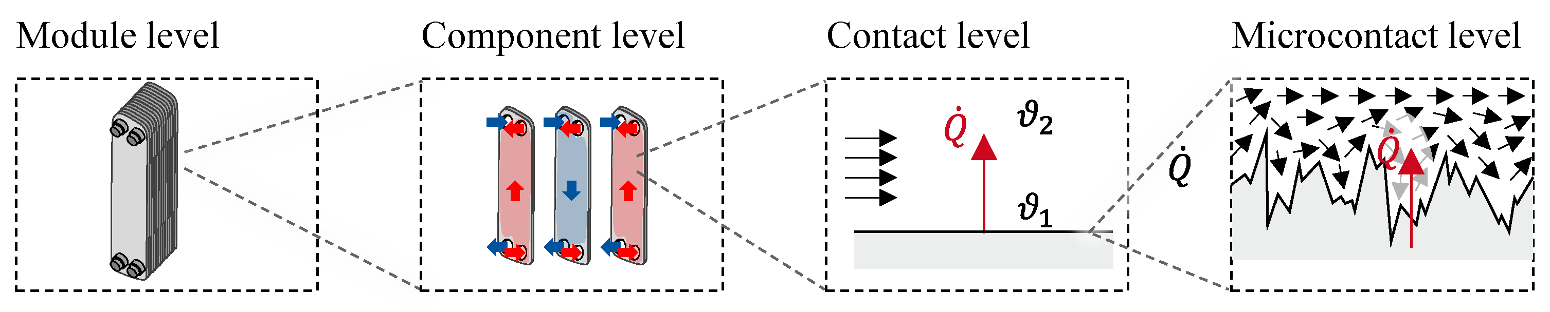
4.3. Determining the System Hierarchy Level of the Solution Elements Through System Decomposition
4.3.1. Determine Potential Solution Elements at Different System Hierarchy Levels
4.3.2. Analysis of the Potential Solution Elements at the Respective System Hierarchy Level
4.3.3. Assessment and Decision on the System Hierarchy Level of the Solution Elements
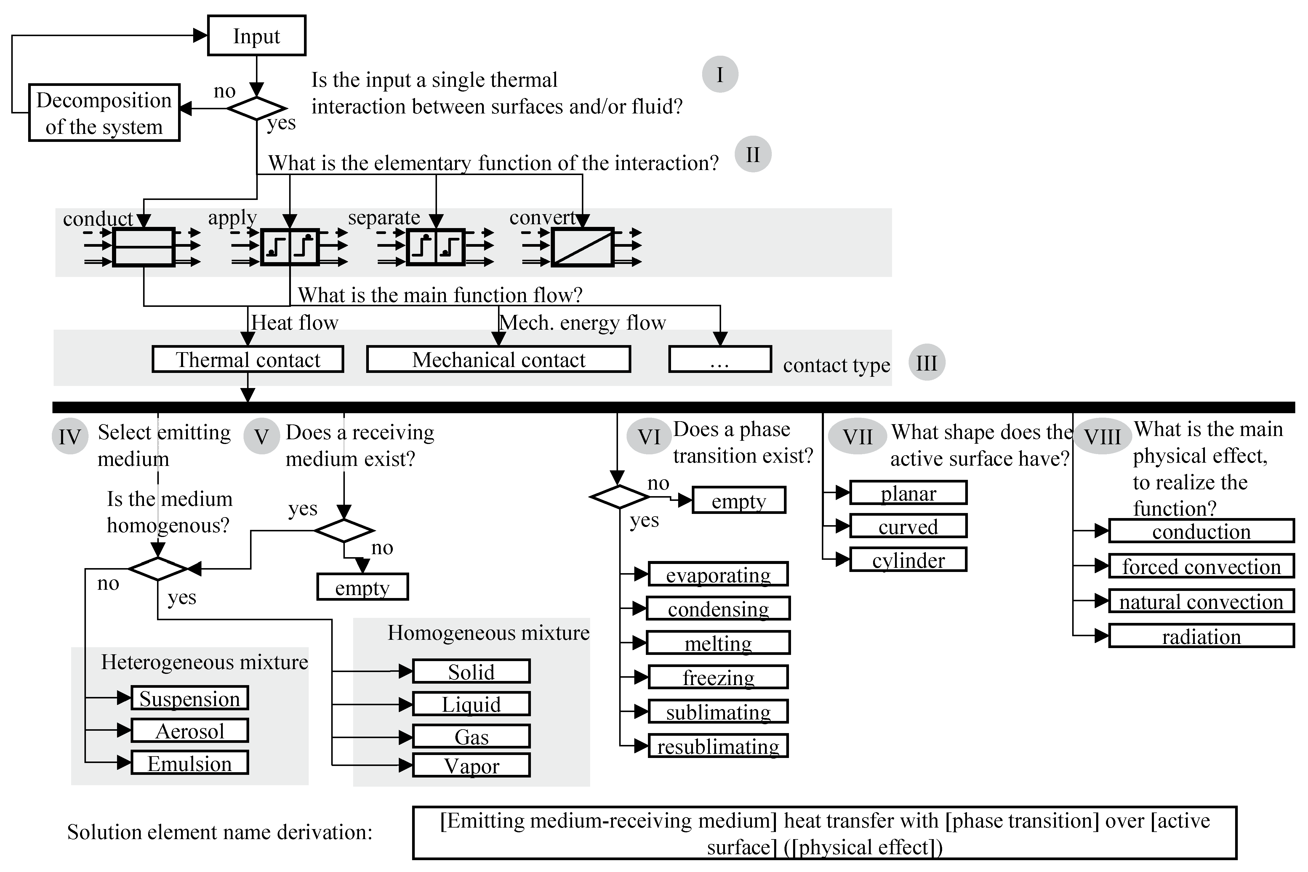
4.4. Developing a Classification Procedure
4.4.1. Classifying Heat Exchanging Processes
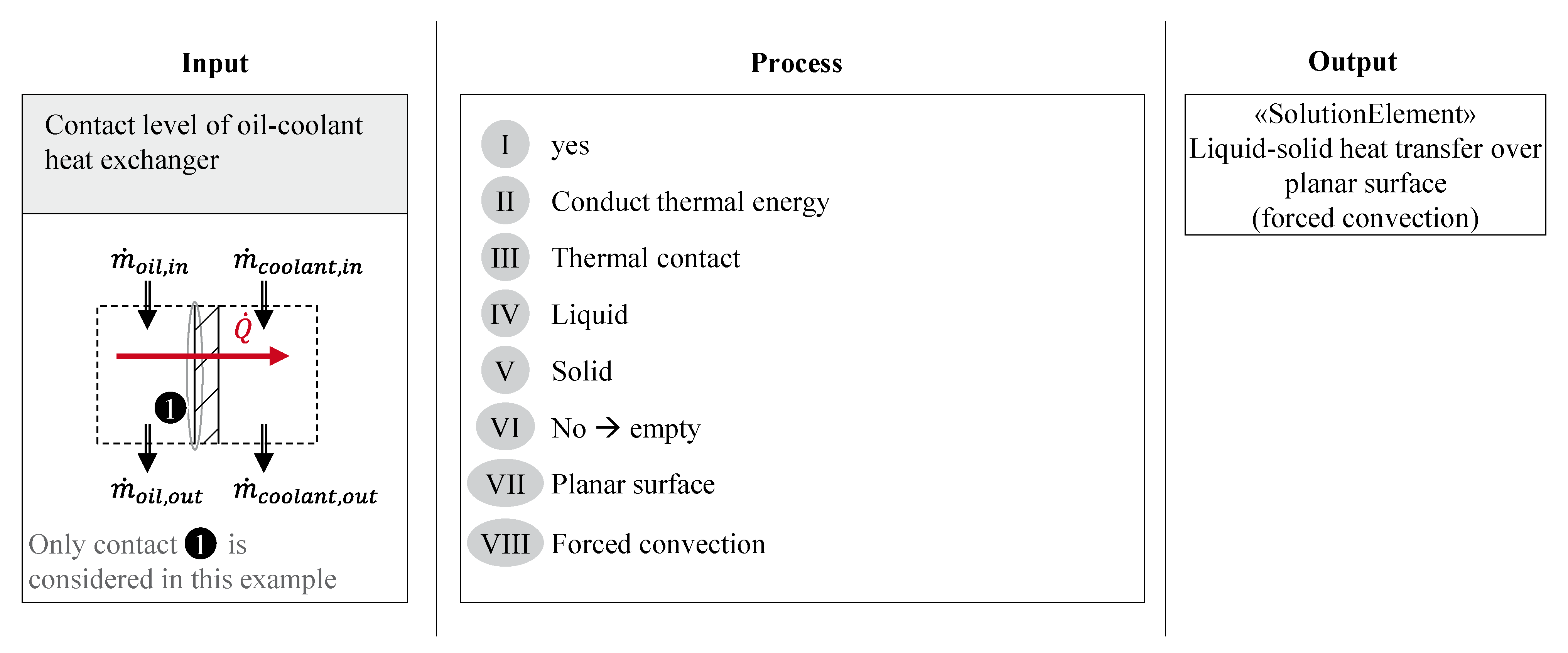
4.4.2. Development of Classification Procedure to Identify Specific Thermal Solution Elements
4.5. Interim Conclusion
- System hierarchy level
- Classification procedure
5. Case Study
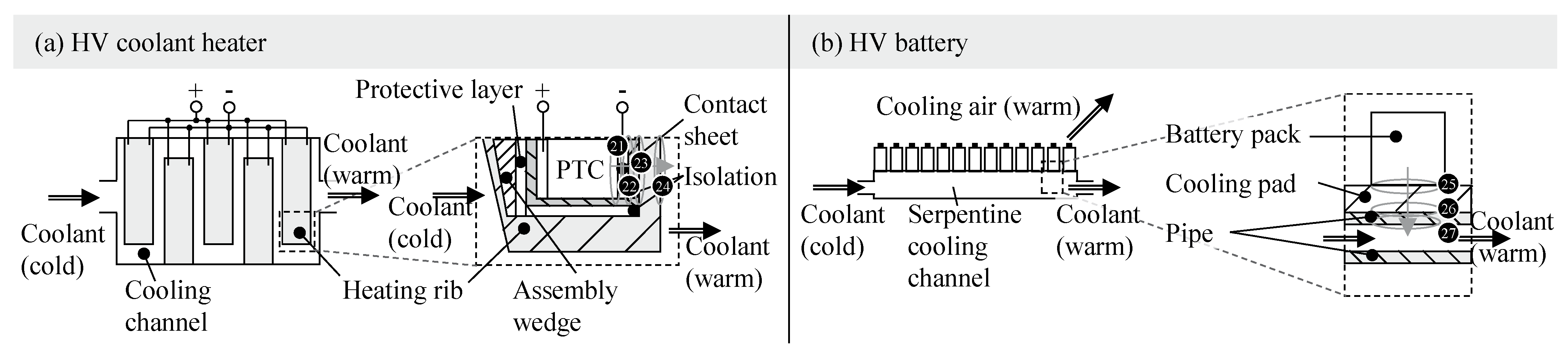
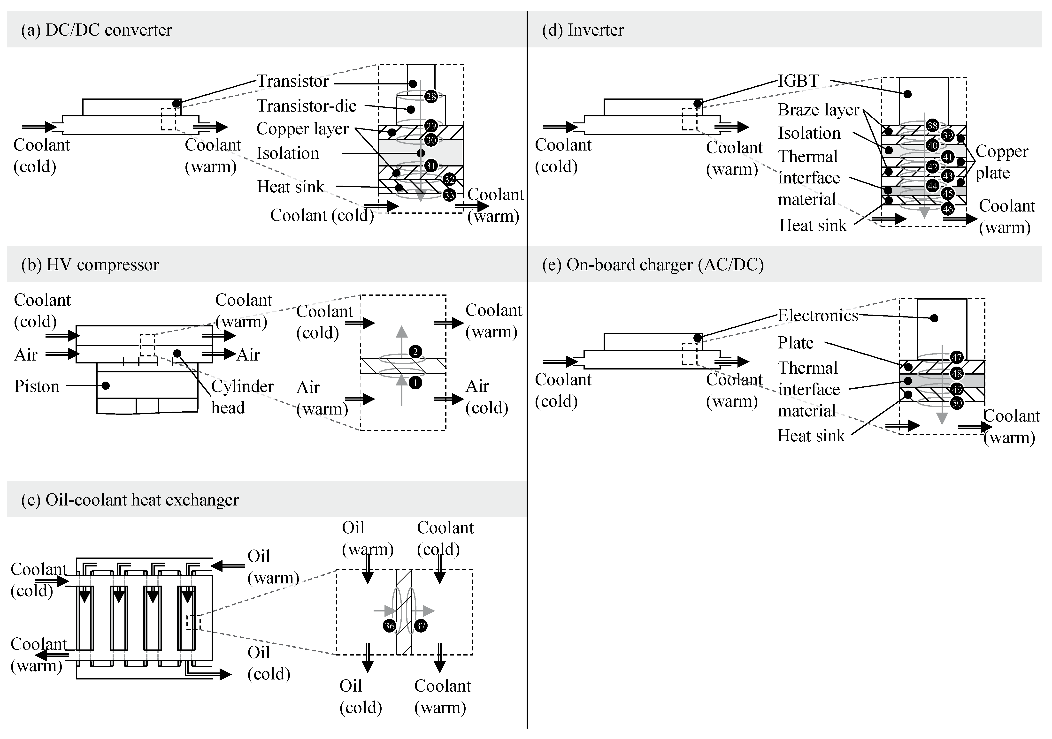
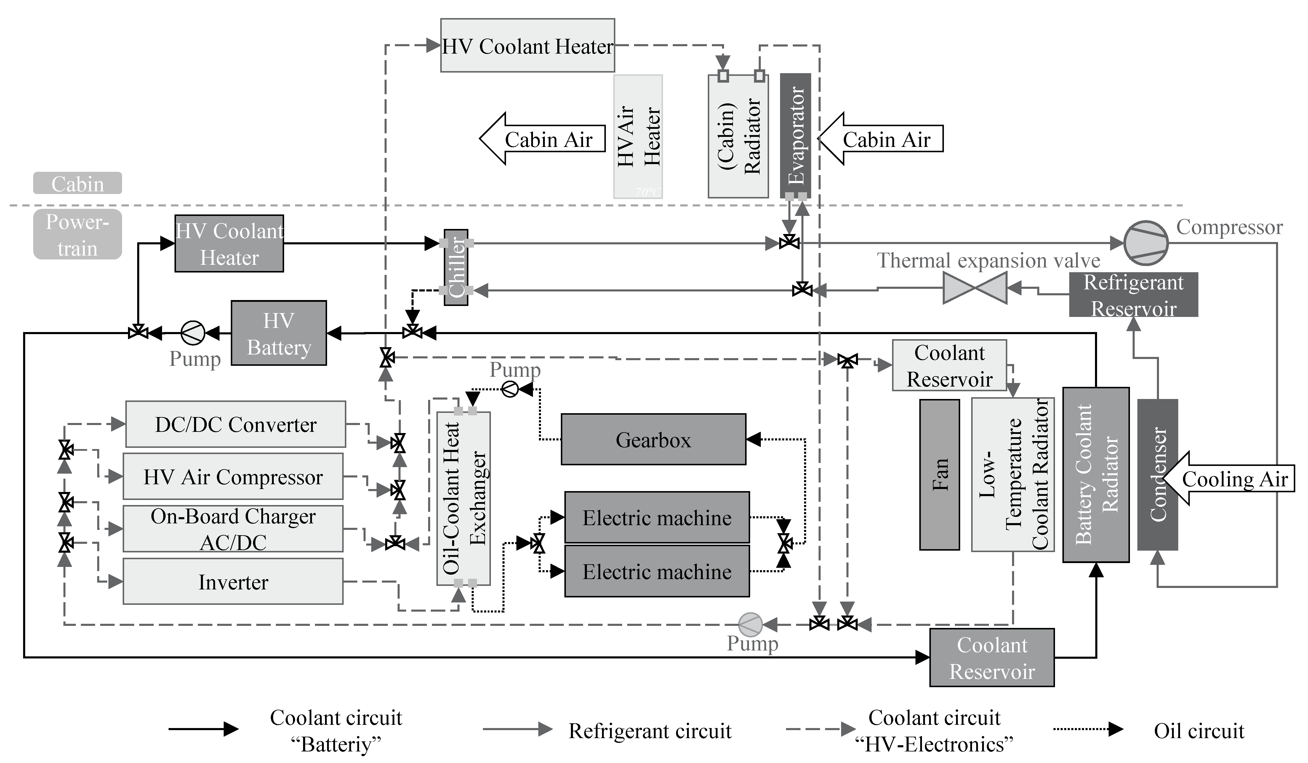
5.1. System of Investigation: Thermal Management System of a Battery Electric Truck
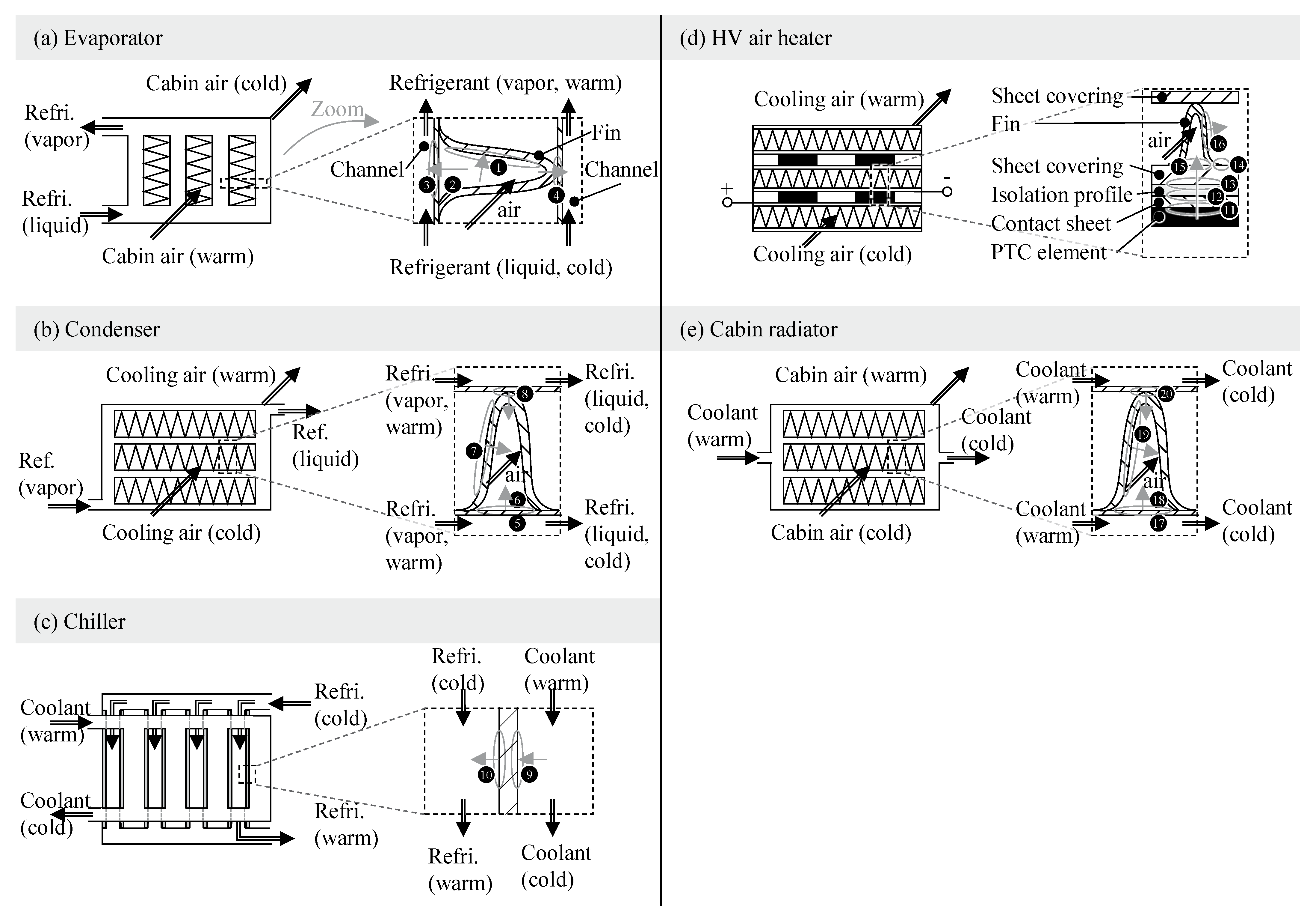
5.2. Application of the Approach on Heat Exchanging Systems
5.3. Identifying Thermal Solution Elements in Heat Exchanging Systems
6. Discussion
7. Conclusions
- As a result of the systematic investigation of system levels, the standardized system level for elementary thermal system elements is the macro contact level, such as the physical interaction between a fluid and a wall surface.
- The developed method offers a guided approach to derive standardised system elements on a uniform system level from existing thermal systems using defined guiding questions (see Figure 3).
- Based on the case study of the thermal management system (TMS), it was demonstrated that over 300,000 individual thermal interactions can be reduced to just 14 recurring system elements.
- These system elements capture both functional and physical relationships and can be utilised to model MBSE system architectures.
Author Contributions
Funding
Data Availability Statement
Conflicts of Interest
Abbreviations
| MBSE | Model-based systems engineering |
| TMS | Thermal management system |
| BEV | Battery electric vehicle |
| VDI | Verein Deutscher Ingenieure |
| SysML | System Modeling Language |
| CSS | Contact and support structure |
| EHD | Elastohydrodynamic |
| R | Requirement |
| HV | High voltage |
| LV | Low voltage |
| AC | Alternating current |
| DC | Direct current |
| PTC | Positive temperature coefficient |
| IGBT | Insulated-gate bipolar transistors |
| Force | |
| Thermal energy flow | |
| Temperature | |
| Mass flow |
Appendix A

| Req. No | Assessment | Argument |
|---|---|---|
| R1 | 1 | Due to the lack of detailing, subordinate requirements such as the dimensions of the panels can be assigned. |
| R2 | 1 | Further technical sub-functions can be identified: Sealing, insulating, conducting, etc. |
| R3 | 1 | Subordinate and reusable solutions can be identified: Gaskets, plates, bolting, etc. |
| R4 | 1 | Not possible, as there are too many different active surfaces with different functions. |
| R5 | 1 | Many active effects, allocation of individual effects is not possible. |
| R6 | 1 | It is not possible to allocate individual materials at this level. |
| R7 | 1 | It is not possible to allocate individual active movements at this level. |
| R8 | 1 | Losses, heat flows, turbulence, etc. are calculated at a subordinate level. |
| R9 | 2 | Connecting is fundamentally possible, but only at higher levels such as the cooling circuit. |
| R10 | 1 | Not a neutral element, as it is a specific assembly. |
| Assessment sum | 11 |
Appendix B
| Req. No | Assessment | Argument |
|---|---|---|
| R1 | 2 | Linking is possible, but detailed requirements are not. |
| R2 | 1 | Further technical sub-functions can be identified: Sealing, insulating, and conducting. |
| R3 | 2 | Subordinate and reusable solutions can be identified, such as the individual panels. |
| R4 | 2 | Active surfaces on the panels are possible, but the panels consist of subordinate active surfaces (heat-exchanging surfaces, sealing surfaces, etc.). |
| R5 | 2 | Possible in principle, but it is not possible to clearly assign the physical effect at this level. |
| R6 | 2 | The assignment of individual materials is not directly possible at this level. |
| R7 | 2 | Further technical sub-functions can be identified: Sealing, insulating, and conducting. |
| R8 | 2 | Temperature curves, heat flows, and heat transfer coefficients are calculated on individual panels or surfaces. |
| R9 | 2 | Basic connecting is possible, but the plates appear as a packet. |
| R10 | 1 | Subordinate and reusable solutions can be identified, such as the individual panels. |
| Assessment sum | 18 |
Appendix C
| Req. No | Assessment | Argument |
|---|---|---|
| R1 | 2 | Requirements for the microscopic surface are more likely than for the microscopic surface, even if they exist. |
| R2 | 3 | Very detailed basic element of heat transfer, but from a functional point of view it is the same function as at the macro level. |
| R3 | 3 | Subordinate reusable solutions cannot be found from a product development perspective. |
| R4 | 2 | Very detailed active surfaces, challenging when aggregating to the wall surface. |
| R5 | 3 | Assignment of physical effects is possible in principle, up to microscopic effects. |
| R6 | 3 | Allocation is possible as the basic system of surface and fluid is considered. |
| R7 | 3 | Allocation is possible as the basic system of surface and fluid is considered. |
| R8 | 2 | Calculations are carried out but with a very detailed question of a fundamental research nature. |
| R9 | 2 | Aggregation becomes challenging at this level due to the very detailed scale. |
| R10 | 2 | Very detailed basic element of heat transfer, but from a functional point of view it is the same function as at the macro level. |
| Assessment sum | 25 |
Appendix D. Detailed Analysis of Heat Exchanging Systems Within the Coolant Circuits and Oil Circuit

References
- Gräßler, I.; Oleff, C. Systems Engineering: Verstehen und Industriell Umsetzen; Springer Vieweg: Berlin, Germany, 2022; ISBN 9783662645161. [Google Scholar]
- Systems Engineering for Automotive Powertrain Development, 1st ed.; Hick, H., Küpper, K., Sorger, H., Eds.; Springer International Publishing: Cham, Germany, 2021; ISBN 9783319996295. [Google Scholar]
- Feldhusen, J.; Grote, K.-H. Pahl/Beitz Konstruktionslehre; Springer: Berlin/Heidelberg, Germany, 2013. [Google Scholar]
- Ehrlenspiel, K.; Meerkamm, H. Integrierte Produktentwicklung: Denkabläufe, Methodeneinsatz, Zusammenarbeit; Hanser: München, Germany, 2013; ISBN 3446435484. [Google Scholar]
- Vajna, S.; Weber, C.; Zeman, K.; Hehenberger, P.; Gerhard, D.; Wartzack, S. CAx Für Ingenieure: Eine praxisbezogene Einführung, 2nd ed.; Springer: Berlin/Heidelberg, Germany, 2018; ISBN 366254623X. [Google Scholar]
- Hussain, M.; Masoudi, N.; Mocko, G.; Paredis, C. Approaches for Simulation Model Reuse in Systems Design—A Review. In Proceedings of the WCX SAE World Congress Experience, Warrendale, PA, USA, 5 April 2022. [Google Scholar]
- Jacobs, G.; Konrad, C.; Berroth, J.; Zerwas, T.; Höpfner, G.; Spütz, K. Function-Oriented Model-Based Product Development. In Design Methodology for Future Products; Krause, D., Heyden, E., Eds.; Springer: Cham, Germany, 2022; pp. 243–263. [Google Scholar] [CrossRef]
- International Council on Systems Engineering. Systems Engineering Handbook. In A Guide for Systems Life Cycle Processes and Activities Version 3.1; International Council on Systems Engineering: San Diego, CA, USA, 2007. [Google Scholar]
- Burton, B.A.; Aragon, R.W.; Bailey, S.A.; Koehler, K.D.; Mayes, L.A. The Reusable Software Library. IEEE Softw. 1987, 4, 25–33. [Google Scholar] [CrossRef]
- Haber, A.; Ringert, J.O.; Rumpe, B. Informationssysteme für die Angewandte Historische Geographie: Beiträge des Symposiums vom 20. März 1999 am Lehrstuhl für Informatik IV der RWTH Aachen; Kulturlandschaft: Zeitschrift für Angewandte Historische Geographi: Regensburg, Germany, 1999; ISBN 0935-3232. Available online: http://aib.informatik.rwth-aachen.de/ (accessed on 17 February 2025).
- Albers, A.; Heimicke, J.; Spadinger, M.; Reiss, N.; Breitschuh, J.; Richter, T.; Bursac, N.; Marthaler, F. A systematic approach to situation-adequate mechatronic system development by ASD—Agile Systems Design. Procedia CIRP 2019, 84, 1015–1022. [Google Scholar] [CrossRef]
- Jagla, P.; Jacobs, G.; Spütz, K.; Berroth, J. Classification of function-oriented solution elements for MBSE. Forsch. Ingenieurwes 2023, 87, 469–477. [Google Scholar] [CrossRef]
- Friedenthal, S.; Griego, R.; Sampson, M. INCOSE Model Based Systems Engineering (MBSE) Initiative. In Proceedings of the In INCOSE 2007 Symposium, San Diego, CA, USA, 24 June 2007. [Google Scholar]
- Estefan, J. Survey of Model-Based Systems Engineering (MBSE) Methodologies; International Council on Systems Engineering: San Diego, CA, USA, 2008. [Google Scholar]
- ISO/IEC/IEEE 15288:2015; Systems and Software Engineering—System Life Cycle Processes. International Organization for Standardization: Geneva, Switzerland, 2015.
- Kruse, B.; Gilz, T.; Shea, K.; Eigner, M. Systematic Comparison of Functional Models in SysML for Design Library Evaluation. Procedia CIRP 2014, 21, 34–39. [Google Scholar] [CrossRef]
- Gilz, T. PLM-Integrated Interdisciplinary System Models in the Conceptual Design Phase Based on Model-Based Systems Engineering; Technische Universität Kaiserslautern: Kaiserslautern, Germany, 2014; ISBN 978-3-941438-73-2. [Google Scholar]
- Gausemeier, J.; Czaja, A.; Wiederkehr, O.; Dumitrescu, R.; Tschirner, C.; Steffen, D. Studie: Systems Engineering in der industriellen Praxis. Tag Des Syst. Eng. 2013, 113–122. [Google Scholar] [CrossRef]
- Hoepfner, G.; Kowalski, J.; Faustmann, C.; Zerwas, T.; Kranabitl, P.; Vafaei, S.; Jacobs, G.; Hick, H. A Classification Method for the Systematic Identification of Models and Workflows in MBSE. In Proceedings of the DS 119: 33rd Symposium Design for X (DFX2022), Hamburg, Germany, 22–23 September 2022; The Design Society: Glasgow, Scotland, 2022; p. 10. [Google Scholar]
- VDI. VDI-Richtlinie 2206: Entwicklung Mechatronischer und Cyber-Physischer Systeme; Verein Deutscher Ingenieure: Harzgerode, Germany, 2021. [Google Scholar]
- Alt, O. Modellbasierte Systementwicklung mit SysML; Carl Hanser Fachbuchverlag: München, Germany, 2012; ISBN 9783446431270. [Google Scholar]
- Gausemeier, J.; Dorociak, R.; Pook, S.; Nyßen, A.; Terfloth, A. Computer-Aided Cross-Domain Modeling of Mechatronic Systems. In Proceedings of the DS 60: DESIGN 2010, the 11th International Design Conference, Dubrovnik, Croatia, 17–20 May 2010; pp. 723–732. [Google Scholar]
- Moeser, G.; Kramer, C.; Grundel, M.; Neubert, M.; Kümpel, S.; Scheithauer, A.; Kleiner, S.; Albers, A. Fortschrittsbericht zur Modellbasierten Unterstützung der Konstrukteurstätigkeit Durch FAS4M; Carl Hanser Verlag: Munich, Germany, 2015; pp. 69–78. [Google Scholar] [CrossRef]
- VDI. Entwicklung Technischer Produkte und Systeme: Verein Deutscher Ingenieure, (2221 Blatt 1); Verein Deutscher Ingenieure: Harzgerode, Germany, 2019. [Google Scholar]
- VDI. Entwicklung Technischer Produkte und Systeme: Verein Deutscher Ingenieure, (2221 Blatt 2); Verein Deutscher Ingenieure: Harzgerode, Germany, 2019. [Google Scholar]
- Zerwas, T.; Jacobs, G.; Spütz, K.; Höpfner, G.; Drave, I.; Berroth, J.; Guist, C.; Konrad, C.; Rumpe, B.; Kohl, J. Mechanical concept development using principle solution models. IOP Conf. Ser. Mater. Sci. Eng. 2021, 1097, 12001. [Google Scholar] [CrossRef]
- Frank, U. Spezifikationstechnik zur Beschreibung der Prinziplösung selbstoptimierender Systeme; Heinz-Nixdorf-Inst: Paderborn, Germany, 2006; ISBN 978-3-935433-84-6. [Google Scholar]
- Moeser, G. Kurzversion FAS4M Methodenguideline: Methodisches Vorgehen im FAS4M-Ansatz; Karlsruhe Institute for Technology: Karlsruhe, Germany, 2016. [Google Scholar]
- Eigner, M.; Dickopf, T.; Schulte, T.; Schneider, M. mecPro 2—Entwurf einer Beschreibungssystematik zur Entwicklung Cybertronischer Systeme mit SysML; Carl Hanser Verlag: Munich, Germany, 2015; pp. 163–172. [Google Scholar] [CrossRef]
- Albers, A.; Christian, Z. Interdisciplinary Systems Modeling Using the Contact & Channel-Model For Sysml. In Proceedings of the DS 68-9: 18th International Conference on Engineering Design (ICED 11), Impacting Society through Engineering Design, Design Methods and Tools, Lyngby/Copenhagen, Denmark, 15–19 August 2011. [Google Scholar]
- Hick, H.; Bajzek, M.; Faustmann, C. Definition of a system model for model-based development. SN Appl. Sci. 2019, 1, 15. [Google Scholar] [CrossRef]
- Faustmann, C.; Bajzek, M.; Hick, H.; Edtmayer, J.; Walch, S. System models and model classification in tribological system development. Syst. Eng. 2020, 23, 783–794. [Google Scholar] [CrossRef]
- Höpfner, G.; Jacobs, G.; Zerwas, T.; Drave, I.; Berroth, J.; Guist, C.; Rumpe, B.; Kohl, J. Model-Based Design Workflows for Cyber-Physical Systems Applied to an Electric-Mechanical Coolant Pump. In IOP Conference Series: Materials Science and Engineering; IOP Publishing: Bristol, UK, 2021; Volume 1097, p. 12004. [Google Scholar] [CrossRef]
- Koller, R.; Kastrup, N. Prinziplösungen zur Konstruktion Technischer Produkte; Springer: Berlin, Germany; New York, NY, USA, 1994; ISBN 3-540-58243-6. [Google Scholar]
- Spütz, K.; Berges, J.; Jacobs, G.; Berroth, J.; Konrad, C. Classification of Simulation Models for the Model-based Design of Plastic-Metal Hybrid Joints. Procedia CIRP 2022, 109, 37–42. [Google Scholar] [CrossRef]
- DIN 32705; Klassifikationssysteme–Erstellung und Weiterentwicklung von Klassifikationssystemen. Deutsches Insitut für Normung: Berlin, Germany, 2021.
- Rodenacker, W.G. Methodisches Konstruieren: Grundlagen, Methodik, Praktische Beispiele, 4th ed.; Springer: Berlin, Germany, 1991; ISBN 9783540539773. [Google Scholar]
- Tschöke, H.; Gutzmer, P.; Pfund, T. Elektrifizierung des Antriebsstrangs; Springer: Berlin/Heidelberg, Germany, 2019. [Google Scholar]
- Wagner, W. Wärmeaustauscher: Grundlagen, Aufbau und Funktion Thermischer Apparate; Vogel Business Media: Würzburg, Germany, 2015; ISBN 9783834333612. [Google Scholar]
- Wagner, W. Wärmeübertragung: Grundlagen; Vogel Buchverlag: Würzburg, Germany, 2011; ISBN 3834332097. [Google Scholar]
- Böckh, P.; von Wetzel, T. Wärmeübertragung: Grundlagen und Praxis; Springer Vieweg: Berlin/Heidelberg, Germany, 2015; ISBN 3662444763. [Google Scholar]
- Sigloch, H. Technische Fluidmechanik, 11. Auflage; Springer: Berlin/Heidelberg, Germany, 2022; ISBN 9783662646281. [Google Scholar]
- Art, L.; Jung, M.; Lutz, R. Thermomanagementsysteme für elektrifizierte Nutzfahrzeuge. MTZ Mot. Z. 2022, 83, 62–67. [Google Scholar] [CrossRef]
- Swales, S.H.; Turnbull, P.F.; Schulze, B.; Poskie, F.R.; Omell, W.J.; Deneszczuk, W.C. Ölgekühlter Motor/Generator für einen Kraftfahrzeugantriebsstrang. DE20101047507 20101005, 5 October 2010. [Google Scholar]
- Weustenfeld, T. Heiz- und Kühlkonzept für Ein Batterieelektrisches Fahrzeug Basierend auf Sekundärkreisläufen. Ph.D. Thesis, Technische Universität Braunschweig, Braunschweig, Germany, 2017. [Google Scholar]
- Kamoshida, O.; Higashiyama, N.; Takagi, M.; Hirayama, T. EVAPORATOR. US201815963998 20180426, 26 April 2018. [Google Scholar]
- Foerster, U.D.I.F. Kraftfahrzeugklimaanlage. DE20101043000 20101027, 27 October 2010. [Google Scholar]
- Wesner, M.; Herrmann, H.G.; Klein, P.; Himmer, T. Heat Exchanger. US201213979473 20120113, 13 January 2012. [Google Scholar]
- Hoerte, T. A Plate Heat Exchanger. EP20040809149 20041222, 22 December 2004. [Google Scholar]
- Bohlender, F.; Niederer, M.; Morgen, C. Electric Heating Device, in Particular for a Motor Vehicle. EP20110010087 20111222, 22 December 2011. [Google Scholar]
- Molt, K. BF03221507 // PTC-Heizung. ATZ Automob. Z. 1998, 100, 496–500. [Google Scholar] [CrossRef]
- Kohl, M.; Walter, C.; Schernikau, J. Heizeinrichtung für ein Kraftfahrzeug. DE201310215180 20130801, 1 August 2013. [Google Scholar]
- Molt, K.D.I. Radiator for a Motor Vehicle. EP19930117850 19931104, 4 November 1993. [Google Scholar]
- Moers, F.; Jacobs, G.; Mennicken, M.; Irnich, L.; Boelsen, K.; Höpfner, G. Reusable solution element libraries for accelerated application of MBSE in mechanical product development. Forsch. Ingenieurwes 2025, 89, 54. [Google Scholar] [CrossRef]
- Cattani, L.; Malavasi, M.; Bozzoli, F.; D’Alessandro, V.; Giammichele, L. Experimental Analysis of an Innovative Electrical Battery Thermal Management System. Energies 2023, 16, 5071. [Google Scholar] [CrossRef]
- Stubkier, S.I.; Østergaard, J.A.; Nielsen, C.R. A Wind Turbine Comprising a Liquid Cooler and a Method for Cooling a Liquid. WO2023EP53272 20230210, 10 February 2023. [Google Scholar]
- Airoldi, G. Inclined Heat Exchanger for a Wind Turbine. EP20190151213 20190110, 10 January 2019. [Google Scholar]
- Bohlender, F.; Schwarzer, A.; Niederer, M. Electric Heating Device. EP20170155418 20170209, 9 February 2017. [Google Scholar]
- Li, M.; Wang, J.; Guo, Q.; Li, Y.; Xue, Q.; Qin, G. Numerical Analysis of Cooling Plates with Different Structures for Electric Vehicle Battery Thermal Management Systems. J. Energy Eng. 2020, 146, 4020037. [Google Scholar] [CrossRef]
- Schicht, H.; Gieras, M.; Huisman, M. Device for Protecting the Radiator of a Motor Vehicle Against Projected Particles. EP19980925538 19980506, 6 May 1998. [Google Scholar]
- Doppelbauer, M. Grundlagen der Elektromobilität: Technik, Praxis, Energie und Umwelt; Springer Vieweg: Wiesbaden/Heidelberg, Germany, 2020; ISBN 9783658297299. [Google Scholar]
- Brost, V.; Kalbacher, K.; Kaesinger, R. Plate Heat Exchanger. EP19960105405 19960404, 4 April 1996. [Google Scholar]
- Dini, P.; Saponara, S. Electro-Thermal Model-Based Design of Bidirectional On-Board Chargers in Hybrid and Full Electric Vehicles. Electronics 2022, 11, 112. [Google Scholar] [CrossRef]
- Tayyara, O.; Da Silva, C.; Nasr, M.; Assadi, A.; Gupta, K.; Trescases, O.; Amon, C.H. Electro-Thermal Codesign Methodology of an On-Board Electric Vehicle Charger. J. Electron. Packag. 2020, 142, 041102. [Google Scholar] [CrossRef]
- Wituski, J.; Kleimaier, A. GaN Leistungsmodul mit IMS Substrat für eine 3-LevelFlying-Capacitorschaltung an 800 V DC; Hochschule für Angewandte Wissenschaften Landshut: Landshut, Germany, 2023. [Google Scholar]
- Hofstetter, T. Air Compressor for a Compressed Air System, in Particular for a Compressed Air Brake System for a Commercial Vehicle. EP20130005925 20131219, 19 December 2013. [Google Scholar]
- Lehmann, R.; Künzler, M.; Moullion, M.; Gauterin, F. Comparison of Commonly Used Cooling Concepts for Electrical Machines in Automotive Applications. Machines 2022, 10, 442. [Google Scholar] [CrossRef]
- Bauer, D. Verlustanalyse bei Elektrischen Maschinen für Elektro-und Hybridfahrzeuge zur Weiterverarbeitung in Thermischen Netzwerkmodellen; Springer: Wiesbaden, Germany, 2019; ISBN 978-3-658-24271-8. [Google Scholar]
- Wang, Y.; Niu, W.; Chen, Y.; Song, G.; Tang, W. Convection heat transfer and temperature analysis of oil jet lubricated spur gears. Ind. Lubr. Tribol. 2016, 68, 624–631. [Google Scholar] [CrossRef]
- Niemann, G.; Winter, H. Maschinenelemente: Band 2: Getriebe Allgemein, Zahnradgetriebe—Grundlagen, Stirnradgetriebe, Zweite, Völlig Neubearbeitete Auflage; Springer: Berlin/Heidelberg, Germany, 2003; ISBN 978-3-662-11874-0. [Google Scholar]
- Czichos, H.; Habig, K.-H. Tribologie-Handbuch: Tribometrie, Tribomaterialien, Tribotechnik; Springer: Wiesbaden, Germany, 2010; ISBN 978-3-8348-0017-6. [Google Scholar]

| Req. No. | Req. Title | Req. Description |
|---|---|---|
| R1 | Specification | The solution element can be linked to technical requirements. |
| R2 | Sub-function | The solution element cannot be divided into technically meaningful sub-functions. |
| R3 | Subordinate reusable solution | The solution element does not contain any subordinate reusable solutions. |
| R4 | Active surface | Active surfaces and pairs of active surfaces can be clearly assigned to the solution element. |
| R5 | Physical effect | A physical effect can be assigned to the solution element that fulfils the function. |
| R6 | Material | Materials can be assigned to the solution element. |
| R7 | Active movement | An active movement can be clearly assigned to the solution element. |
| R8 | Engineering models | Established engineering models are used at the same level as the solution element. |
| R9 | Connection | The solution element can be connected with other solution elements to form a system architecture. |
| R10 | Product neutral | The solution element is a product-neutral element and can, therefore, be used universally. |
| System Hierarchy Level | Solution Element | Elementary Function | Functional Flow | Active Surfaces | Physical Effect |
|---|---|---|---|---|---|
| Module level | Total heat exchanger | Separate or collect energy | In: Volume flow; Out: Volume flow | Not clearly determinable | Not clearly determinable |
| Component level | Heat transfer plates | Separate or collect energy | In: Volume flow; Out: Volume flow | Occurring heat-emitting plates | Convection at the plates |
| Contact level | Macroscopic fluid-wall heat transfer | Separate or collect energy | In: Volume flow, heat flow; Out: Volume flow | Single heat transferring surface with the wetted fluid | Convection on idealised surface |
| Microcontact level | Microscopic fluid-wall heat transfer | Separate or collect energy | In: Volume flow, heat flow; Out: Volume flow | Surface roughness and wetted fluid | Convection on roughness |
| Req. No | Assessment | Argument |
|---|---|---|
| R1 | 3 | Linking with basic requirements is possible. |
| R2 | 3 | Basic element of heat transfer, there are no subordinate functions here from a functional orientation perspective. |
| R3 | 3 | Subordinate reusable solutions cannot be found from a product development perspective. |
| R4 | 3 | Active surfaces can be assigned by the macroscopic surface. |
| R5 | 3 | Assignment of physical effects is possible; therefore, this element is used for description in physics. |
| R6 | 3 | Assignment is possible because the basic system of surface and fluid is considered. |
| R7 | 3 | Assignment is possible because the basic system of surface and fluid is considered, so moving/no moving surface or fluid. |
| R8 | 3 | Heat transfer coefficients and turbulence are calculated at this level. |
| R9 | 3 | Aggregation is possible, as both fluid and wall surfaces are considered. |
| R10 | 3 | In the field of heat transfer, it is product-neutral, as different systems can be aggregated with this element. |
| Assessment sum | 30 |
| Solution Element | Total Heat Exchanger | Heat Transfer Plates | Macroscopic Fluid-Wall Heat Transfer | Microscopic Fluid-Wall Heat Transfer |
|---|---|---|---|---|
| Assessment sum | 11 | 18 | 30 | 25 |
| Decision | Selected system hierarchy level |
| Classification Characteristics | ||||||
|---|---|---|---|---|---|---|
| Elementary Function | Elemental Function Flow | Medium, Mixture | Phase Transition | Active Surface | Physical Effect | |
| Specification | Conduct | Heat flow | Solid | Evaporating | Planar | Forced convection |
| Separate | Mass flow | Liquid | Condensing | Curved | Natural convection | |
| Convert | Gas | Melting | Cylinder | Conduction | ||
| Apply | Suspension | Freezing | Radiation | |||
| Aerosol | Sublimating | |||||
| Emulsion | Resublimating | |||||
| Number of Interactions in Figure 6, Figure A1, Figure A2 and Figure A3 | Derived Thermal Solution Element by Applying the Classification Procedure of Figure 3 | |||||||||||||
|---|---|---|---|---|---|---|---|---|---|---|---|---|---|---|
| 1 | Gas-solid heat transfer over curved surface (forced convection) | |||||||||||||
| 34 | Gas-solid heat transfer over cylinder surface (forced convection) | |||||||||||||
| 2 | Gas-solid heat transfer over planar surface (forced convection) | |||||||||||||
| 9 | 17 | 36 | Liquid-solid heat transfer over planar surface (forced convection) | |||||||||||
| 7 | 16 | 19 | Solid-gas heat transfer over curved surface (forced convection) | |||||||||||
| 6 | 15 | 18 | Solid-gas heat transfer over planar surface (forced convection) | |||||||||||
| 27 | 35 | 51 | Solid-liquid heat transfer over cylinder surface (forced convection) | |||||||||||
| 24 | 33 | 37 | 46 | 50 | Solid-liquid heat transfer over planar surface (forced convection) | |||||||||
| 52 | Solid-liquid heat transfer over curved surface (forced convection) | |||||||||||||
| 4 | 8 | 11–14 | 20 | 21–23 | 25–16 | 28–32 | 38–43 | 47 | Solid-solid heat transfer over planar surface (conduction) | |||||
| 44 | 48 | Solid-suspension heat transfer over planar surface (conduction) | ||||||||||||
| 3 | 10 | Solid-vapour heat transfer with evaporating fluid over the planar surface (forced convection) | ||||||||||||
| 45 | 49 | Suspension-solid heat transfer over planar surface (conduction) | ||||||||||||
| 5 | Vapour-solid heat transfer with condensing fluid over the planar surface (forced convection) | |||||||||||||
| Evaporator | Condenser | Chiller | HV air heater | Cabin radiator * | HV coolant heater | HV battery | DC/DC Converter | HV compressor | Oil-coolant heat exchanger | Inverter | On-board charger | Electric motor | Gearbox | * is equal to the low-temperature radiator and battery coolant radiator |
| Systems/components of circuits | ||||||||||||||
Disclaimer/Publisher’s Note: The statements, opinions and data contained in all publications are solely those of the individual author(s) and contributor(s) and not of MDPI and/or the editor(s). MDPI and/or the editor(s) disclaim responsibility for any injury to people or property resulting from any ideas, methods, instructions or products referred to in the content. |
© 2025 by the authors. Licensee MDPI, Basel, Switzerland. This article is an open access article distributed under the terms and conditions of the Creative Commons Attribution (CC BY) license (https://creativecommons.org/licenses/by/4.0/).
Share and Cite
Jagla, P.; Jacobs, G.; Derpa, V.; Irnich, L.; Höpfner, G.; Wischmann, S.; Berroth, J. System Elements Identification Method for Heat Transfer Modelling in MBSE. Systems 2025, 13, 251. https://doi.org/10.3390/systems13040251
Jagla P, Jacobs G, Derpa V, Irnich L, Höpfner G, Wischmann S, Berroth J. System Elements Identification Method for Heat Transfer Modelling in MBSE. Systems. 2025; 13(4):251. https://doi.org/10.3390/systems13040251
Chicago/Turabian StyleJagla, Patrick, Georg Jacobs, Vincent Derpa, Lukas Irnich, Gregor Höpfner, Stefan Wischmann, and Joerg Berroth. 2025. "System Elements Identification Method for Heat Transfer Modelling in MBSE" Systems 13, no. 4: 251. https://doi.org/10.3390/systems13040251
APA StyleJagla, P., Jacobs, G., Derpa, V., Irnich, L., Höpfner, G., Wischmann, S., & Berroth, J. (2025). System Elements Identification Method for Heat Transfer Modelling in MBSE. Systems, 13(4), 251. https://doi.org/10.3390/systems13040251