Article

Hierarchical Coordinated Energy Management Strategy for Hybrid Energy Storage System in Electric Vehicles Considering the Battery’s SOC

1
The Key Laboratory of Vehicle Power and Transmission System, Hunan Institute of Engineering, Xiangtan 411104, China
2
School of Management, Hunan Institute of Engineering, Xiangtan 411104, China
*
Author to whom correspondence should be addressed.
Systems 2023, 11(10), 498; https://doi.org/10.3390/systems11100498
Submission received: 2 August 2023 / Revised: 14 September 2023 / Accepted: 26 September 2023 / Published: 28 September 2023
(This article belongs to the Section Systems Engineering)

Abstract

:
This paper combines two types of energy storage components, the battery and supercapacitor (SC), to form a fully active hybrid energy storage system (HESS) as a power source for electric vehicles (EVs). At the same time, a hierarchical coordinated energy management strategy based on model predictive control (HCEMS-MPC) is presented. Firstly, the mathematical model of the fully active HESS is obtained based on Kirchhoff’s law and state-space modeling technology. Secondly, considering the state of charge (SOC) of the battery, a fuzzy-control-based upper-level energy management strategy (EMS) is proposed to optimize power allocation and to generate a reference current for a lower-level current controller. Then, a lower-level current predictive controller is designed to achieve accurate current tracking. Finally, a lower-level voltage sliding mode controller is designed to stabilize the bus voltage. Compared with previous works, the HCEMS-MPC strategy only needs to adjust the weight matrix and the reaching term to avoid the problem of excessive controller parameters. The simulation results, under different driving conditions, show that the HCEMS-MPC strategy has a better performance with respect to its fast response, error reduction, and robust stability. In addition, the SOC of the battery decreases more slowly, and the final SOC value significantly increases, thereby extending the single-discharge cycle time of the battery and improving the service life of the battery.

1. Introduction

With the increasingly serious problem of energy shortage and environmental pollution, EVs have become one of the ideal vehicle models for future vehicle development due to their advantages in energy conservation and environmental protection. As the power source of most EVs, although batteries have a high energy density, they also have the drawbacks of a low power density and short cycle life. Compared with the battery, the SC has a high power density and long cycle life. This complementary feature makes the battery–SC HESS an effective energy storage solution in application scenarios requiring a high power density and high energy density [1,2]. In the application of EVs, a vehicle has repeated acceleration and braking states. An SC can effectively reduce the peak current of the battery, recover the braking energy, and avoid the frequent charging and discharging of the battery with a large current, thus extending the battery life [3,4]. The HESS can be divided into three types according to the degree of control freedom: the fully active HESS, semiactive HESS, and passive HESS. Each energy source of the fully active HESS is independently controllable, with better control effects and a wider range of applications [5].
Previously, to maximize the benefits of the HESS, researchers carried out many pieces of research, which can mainly be divided into two categories: one is the design of an upper-level EMS to distribute the required power or load current between the battery and the SC, and the other is the design of a lower-level control strategy to achieve the matching tracking of the output power or current [6]. The dynamic programming (DP) method was used to deal with the global optimization problem to obtain the best energy distribution result for the HESS. Nevertheless, the DP algorithm has the problems of a high computing burden and large memory resource requirements [7]. A neural-network- based power prediction method and power allocation strategy were proposed to reduce the energy consumption cost of the HESS. Nevertheless, the neural network needs a large number of high-quality samples for training to ensure the correctness of the results [8]. A real-time model predictive control EMS was proposed to optimally distribute the load current between the battery and the SC to minimize the power loss of the HESS. Nevertheless, this method requires a high model accuracy [9]. Several EMSs, such as the rule-based, MPC-based, fuzzy-based, and filtration-based EMSs, were compared, and the results show that the rule-based and fuzzy-based EMSs can have a better performance [10].
For the HESS, the normal load demand can be predicted and estimated, but as a typical multivariable and strongly coupled nonlinear system, due to the time-varying system parameters and external uncertainty interference, the actual load demand may fluctuate, leading to control problems, such as an unknown load disturbance. This will directly affect whether the optimal power/current distribution can operate as expected. Therefore, the control problems associated with the HESS need to be cracked. A fractional-order proportional integral derivative (FOPID) control strategy was proposed for the coordinated control of fuel cells and SCs in the HESS to improve the power quality. Nevertheless, the PID controller is very sensitive to changes in the parameters and cannot maintain optimal control in real time, and the control performance will be affected [11]. To provide power to the load promptly, a terminal sliding mode controller was proposed to achieve the stable tracking of the current and to obtain a stable DC bus voltage for the HESS. Nevertheless, the inherent jitter of sliding mode control can hurt the control effectiveness [12]. An L2-gain adaptive robust control (L2-ARC) strategy was proposed which combines the port-controlled Hamiltonian (PCH) model and the L2-gain control method to achieve the underlying control of the HESS. Nevertheless, the controller design is more complicated [13]. In recent years, model predictive control technology has been widely used in urban traffic control [14], vehicle control [15], motor control [16], power electronics [17], power systems [18], and other fields due to its excellent control performance. Some scholars have applied the MPC method to HESS control to deal with the possible interference and noise in the system and to improve the robustness of the system. A model predictive current control strategy based on a constant switching frequency was proposed for the HESS in DC microgrids which can realize fast and accurate current regulation and can reduce current fluctuation. Nevertheless, the regulation of the bus voltage is ignored, which undoubtedly affects the overall performance of the HESS [19]. For the three-stage bidirectional DC converter of the HESS, an MPC method performed by calculating the outer steady reference value and inner dynamic rolling optimization was used to make the current track the predicted value, thereby reducing the system current ripple. Nevertheless, this method involves a large number of parameters and has high computational complexity. In practical applications, how to solve the problem of excessive computational complexity also needs to be considered [20]. An MPC control strategy with three cost functions was designed to stabilize the DC bus voltage for the different control modes of the HESS. Nevertheless, the impact of the energy storage component lifespan on the HESS’ performance has been ignored, which will increases the usage costs [21].
In this paper, the HCEMS-MPC strategy for the HESS in Evs is presented. Compared with previous works, the contributions of this work are threefold. Firstly, the proposed HCEMS-MPC strategy only needs to adjust the weight matrix and the reaching term to avoid complex parameter settings and to reduce the computational complexity. Secondly, the proposed HCEMS-MPC strategy considers the battery’s SOC, utilizes fuzzy control to achieve optimal power allocation, and obtains the current reference value, which can effectively extend the single-discharge cycle time of the battery and improve its service life. Finally, due to the use of a hierarchical design, the top-level energy management strategy and the low-level current/voltage control strategy can achieve good matching in different driving cycles and have a good performance with respect to its fast response, error reduction, and robust stability.
The rest of this paper Is as follows: Section 2 describes the topology and the mathematical equations of the HESS. The HCEMS-MPC strategy design is presented in Section 3. Section 4 introduces the simulation results and analysis. The discussion is presented in Section 5. The conclusion is presented in Section 6.

2. The Topology of Battery–SC HESS

As shown in Figure 1, the fully active HESS’ topology consists of the battery, the SC, two bidirectional DC/DC converters, and the driving system (a DC/AC inverter and drive motor). The bidirectional DC/DC converter consists of two insulated gate bipolar transistors (IGBTs), an inductor, and a capacitor. For ease of control, the drive system is modeled as a load with variable current iload. In this paper, a variable current source is used to simulate it. The switches Q1, Q2, Q3, and Q4 of the IGBTs adopt the complementary PWM control method. When Q1 is on (off), Q2 is off (on), and Q3 and Q4 are the same. Based on Kirchhoff’s law and the state-space modeling techniques, the mathematical equations of the fully active HESS’ topology under ideal conditions are as follows:
L 1 d i 1 d t = V 1 i 1 R L 1 + ( u 1 1 ) V dc
L 2 d i 2 d t = V 2 i 2 R L 2 + ( u 2 1 ) V dc
C dc d V dc d t = ( 1 u 1 ) i 1 + ( 1 u 2 ) i 2 i load
where L1 and L2 are the inductors of the battery side and the SC side; i1 and i2 are the currents flowing through them; RL1 and RL2 are the series resistances of L1 and L2; C1 and C2 are the filter capacitors of the battery side and the SC side; Cdc is the DC bus capacitor; Ebat and Esc are the nominal voltages of the battery and the SC; V1, V2, and Vdc are the voltages corresponding to capacitors C1, C2, and Cdc; and u1 and u2 are the duty cycle of switches S1 and S3.

3. The HCEMS-MPC Strategy of HESS

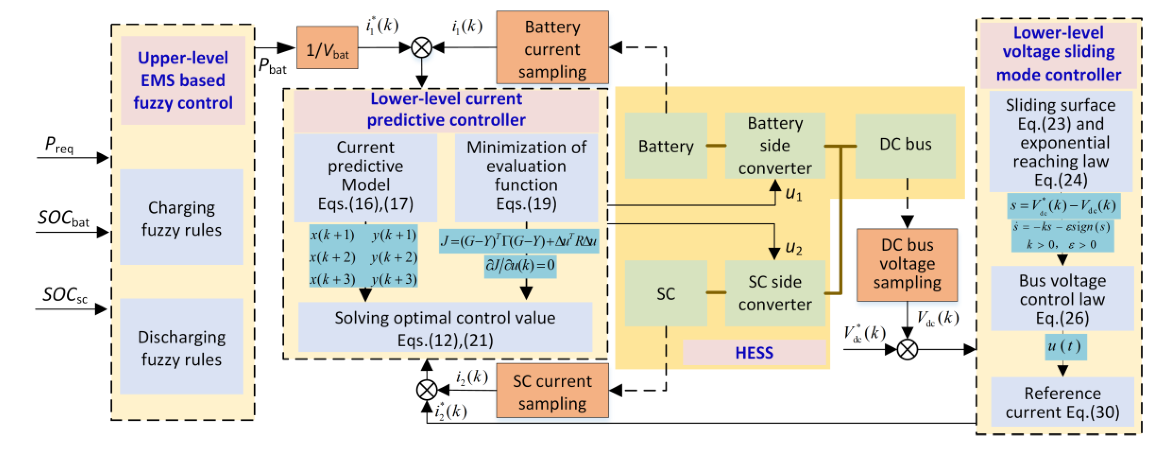
As shown in Figure 2, the proposed HCEMS-MPC strategy includes three parts: upper-level energy management based on fuzzy control, a lower-level current predictive controller, and a lower-level voltage sliding mode controller. This section first proposes an upper-level EMS based on fuzzy control which improves the service life of the HESS while dynamically adjusting the load power distribution and generating the current reference values. Then, a lower-level current prediction controller is proposed to predict the future state of the battery/SC current within a certain prediction range and to define the control variables and the evaluation functions for the predicted state, and the optimal control action is obtained. Finally, a lower-level voltage sliding mode controller is designed to stabilize the bus voltage of the HESS.

3.1. Upper-Level Energy Management Based on Fuzzy Control

For the HESS, in addition to considering the high stability of the system, it is also necessary to make full use of the working characteristics of the battery and SC to dynamically adjust the distribution of the load power and to improve its service life, and this section proposes an EMS based on fuzzy control to achieve the above objectives. The required power Preq, the state of charge of the battery SOCbat, and the state of charge of the SC SOCsc are selected as the inputs of the fuzzy controller, and the battery power distribution coefficient Kbat is selected as the output of the fuzzy controller. Thus, the battery power Pbat and the SC power Psc can be obtained as follows:
P bat = K bat P req
P sc = P req P bat = ( 1 K bat ) P req
Thus, the current reference values i 1 * and i 2 * can be calculated as follows:
i 1 * = P bat / V bat
i 2 * = P sc / V sc
The definitions of the fuzzy domain and fuzzy language values are shown in Table 1, where S means small, M means medium, L means large, and TL means very large. The following are explanations for the fuzzy domain settings of each variable:
Preq: The actual domain of Preq is [0, Pmax]. The quantization factor Kd = 1/Pmax is used to change the Preq from the actual domain to the fuzzy domain. Pmax is the maximum power value; therefore, the fuzzy domain range of P is [0, 1].
SOCbat: The actual domain of SOCbat is [0, 1]. Considering that excessive discharge can cause damage to the battery, the fuzzy domain of SOCbat is set to [0.2, 1].
SOCsc: The actual domain of SOCsc is also [0, 1]. Considering that the discharge capacity of the SC is stronger than that of the battery and that it avoids complete discharge, the fuzzy domain of SOCsc is set to [0.1, 1].
Kbat: Kbat is used as the battery power distribution coefficient, and the actual domain is [0, 1]; therefore, the fuzzy domain is also set to [0, 1].
With the positive and negative conversion of the load power, the HESS also has the two working modes of charging and discharging. Therefore, the Mamdani structures of “three inputs and one output” and “two inputs and one output” correspond to the discharging and charging modes of the HESS, respectively. Considering the influence of the SOC of the battery on the service life of the HESS, the designed fuzzy rules are shown in Table 2 and Table 3. Figure 3 shows the membership function of the fuzzy variables, and the three-dimensional curved surface diagram of the fuzzy rules is shown in Figure 4.

3.2. The Lower-Level Current Predictive Controller

The MPC can predict the system output over a certain period based on the prediction model and can generate optimal control through rolling optimization, with a good tracking performance and strong robustness [22]. The objective of the current predictive controller is to achieve the fast-tracking control of the current loop. Based on Equations (1) and (2), the following can be obtained:
d i 1 / d t d i 2 / d t = R L 1 / L 1 0 0 R L 2 / L 2 i 1 i 2 + V dc / L 1 0 0 V dc / L 2 u 1 u 2 + ( V 1 V dc ) / L 1 ( V 2 V dc ) / L 2
The sampling time is set as Ts, and the first-order Euler formula is used to discretize Equation (8) to obtain the following:
i 1 ( k + 1 ) i 2 ( k + 1 ) = 1 R L 1 T s / L 1 0 0 1 R L 2 T s / L 2 i 1 ( k ) i 2 ( k ) + V dc T s / L 1 0 0 V dc T s / L 2 u 1 ( k ) u 2 ( k ) + ( V 1 V dc ) / L 1 ( V 2 V dc ) / L 2
Therefore,
i 1 ( k ) i 2 ( k ) = 1 R L 1 T s / L 1 0 0 1 R L 2 T s / L 2 i 1 ( k 1 ) i 2 ( k 1 ) + V dc T s / L 1 0 0 V dc T s / L 2 u 1 ( k 1 ) u 2 ( k 1 ) + ( V 1 V dc ) / L 1 ( V 2 V dc ) / L 2
In combination with Equations (9) and (10), the following can be obtained:
Δ i 1 ( k + 1 ) Δ i 2 ( k + 1 ) = 1 R L 1 T s / L 1 0 0 1 R L 2 T s / L 2 Δ i 1 ( k ) Δ i 2 ( k ) + V dc T s / L 1 0 0 V dc T s / L 2 Δ u 1 ( k ) Δ u 2 ( k )
where
Δ i 1 ( k + 1 ) Δ i 2 ( k + 1 ) = i 1 ( k + 1 ) i 1 ( k ) i 2 ( k + 1 ) i 2 ( k ) ,   Δ i 1 ( k ) Δ i 2 ( k ) = i 1 ( k ) i 1 ( k 1 ) i 2 ( k ) i 2 ( k 1 ) ,   Δ u 1 ( k ) Δ u 2 ( k ) = u 1 ( k ) u 1 ( k 1 ) u 2 ( k ) u 2 ( k 1 )
Define the state variables x(k), input variables u(k), and output variables y(k) as follows:
x ( k ) = Δ i 1 ( k ) Δ i 2 ( k ) i 1 ( k ) i 2 ( k ) T ,   u ( k ) = u 1 ( k ) u 2 ( k ) T ,   y ( k ) = i 1 ( k ) i 2 ( k ) T .
The following discretized state-space representation can be obtained:
x ( k + 1 ) = A x ( k ) + B Δ u ( k ) y ( k ) = C x ( k )
where
A = 1 R L 1 T s / L 1 0 0 0 0 1 R L 2 T s / L 2 0 0 1 R L 1 T s / L 1 0 1 0 0 1 R L 2 T s / L 2 0 1 ,   B = V dc T s / L 1 0 0 V dc T s / L 2 V dc T s / L 1 0 0 V dc T s / L 2 ,   C = 0 0 1 0 0 0 0 1 .
The output prediction equation is derived based on the above prediction model, and the derivation follows the following two assumptions:
(1)
The prediction time domain is p, the control time domain is m, and mp.
(2)
Outside of the control time domain, the control variable remains unchanged; that is, Δu(k + i) = 0, i = m, m + 1, …, p − 1.
Assuming that the control variable remains unchanged and m = 1, we can obtain the following:
u ( k ) = u ( k + 1 ) = u ( k + 2 )
Therefore,
Δ u ( k + 1 ) = Δ u ( k + 2 ) = 0
Predict the state variable of the future cycle in the kth cycle, and the predicted value can be obtained as follows:
x ( k + 1 k ) = A x ( k ) + B Δ u ( k ) x ( k + 2 k ) = A x ( k + 1 ) + B Δ u ( k + 1 ) = A 2 x ( k ) + A B Δ u ( k ) x ( k + 3 k ) = A x ( k + 2 ) + B Δ u ( k + 2 ) = A 3 x ( k ) + A 2 B Δ u ( k ) x ( k + p k ) = A x ( k + p 1 ) + B Δ u ( k + p 1 ) = A p x ( k ) + A p 1 B Δ u ( k )
where x ( k + i k ) , i = 1 , 2 , 3 p is the predicted value in the ideal state obtained at the beginning of the kth cycle. The three-step prediction method is adopted; that is, the predicted time domain p = 3. The predicted output value can be obtained by combining Equations (13) and (16):
y ( k + 1 ) y ( k + 2 ) y ( k + 3 ) = C A C A 2 C A 3 x ( k ) + C B C A B C A 2 B Δ u ( k )
where the matrices CA, CA2, CA3, CB, CAB, and CA2B in (13) are given as follows:
C A = 1 R L 1 L 1 T s 0 1 0 0 1 R L 2 L 2 T s 0 1 , C A 2 = ( 1 R L 1 L 1 T s ) ( 2 R L 1 L 1 T s ) 0 1 0 0 ( 1 R L 2 L 2 T s ) ( 2 R L 2 L 2 T s ) 0 1 , C A 3 = ( 1 R L 1 L 1 T s ) [ ( R L 1 L 1 T s ) 2 3 ( R L 1 L 1 T s ) + 3 ] 0 1 0 0 ( 1 R L 2 L 2 T s ) [ ( R L 2 L 2 T s ) 2 3 ( R L 2 L 2 T s ) + 3 ] 0 1 , C B = V dc L 1 T s 0 0 V dc L 2 T s , C A B = ( 2 R L 1 L 1 T s ) V dc L 1 T s 0 0 ( 2 R L 2 L 2 T s ) V dc L 2 T s , C A 2 B = [ ( R L 1 L 1 T s ) 2 3 ( R L 1 L 1 T s ) + 3 ] V dc L 1 T s 0 0 [ ( R L 2 L 2 T s ) 2 3 ( R L 2 L 2 T s ) + 3 ] V dc L 2 T s .
Define Y = [y(k + 1) y(k + 2) y(k + 3)]T, β = [CA CA2 CA3]T, ψ = [CB CAB CA2B]T, and the following can be obtained:
Y   =   β x ( k )   +   ψ Δ u ( k )
In order to obtain the optimal control value, let the reference value be y * ( k ) = i 1 * ( k ) i 2 * ( k ) T , and define the evaluation function J as follows:
J = ( G Y ) T Γ ( G Y ) + Δ u T R Δ u
where G = [I I I]Ty*(k), I is a second-order identity matrix, and Г and R are both positive definite weight matrices. Г determines the proportion of the control error in the evaluation index at each time in the future, and R is the constraint on the change in the control value; here, Г = diag(1, 1), and R = diag(r1, r2).
Let the evaluation function be the minimum; that is, J / Δ u ( k ) = 0 . Then, the optimal solution can be solved as follows:
Δ u ( k ) = ( ψ T ψ + R ) 1 [ ψ T G ¯ y * ( k ) ψ T G x ( k ) ]
where ψ T G ¯ is a matrix composed of the last two columns of ψ T G and where the increments Δ u 1 ( k ) and Δ u 2 ( k ) of the optimal control value in the corresponding calculation period can be obtained by Equation (20) as follows:
Δ u 1 ( k ) Δ u 2 ( k ) = V dc T s L 1 [ ( R L 1 T s L 1 ) 2 4 R L 1 T s L 1 + 6 ] [ i 1 * ( k ) i 1 ( k ) ] ( 1 R L 1 T s L 1 ) { 1 + ( 2 R L 1 T s L 1 ) 2 + [ ( R L 1 T s L 1 ) 2 3 R L 1 T s L 1 + 3 ] 2 } ( V dc T s L 1 ) 2 { 1 + ( 2 R L 1 T s L 1 ) 2 + [ ( R L 1 T s L 1 ) 2 3 R L 1 T s L 1 + 3 ] 2 } + r 1 V dc T s L 2 [ ( R L 2 T s L 2 ) 2 4 R L 2 T s L 2 + 6 ] [ i 2 * ( k ) i 2 ( k ) ] ( 1 R L 2 T s L 2 ) { 1 + ( 2 R L 2 T s L 2 ) 2 + [ ( R L 2 T s L 2 ) 2 3 R L 2 T s L 2 + 3 ] 2 } ( V dc T s L 2 ) 2 { 1 + ( 2 R L 2 T s L 2 ) 2 + [ ( R L 2 T s L 2 ) 2 3 R L 2 T s L 2 + 3 ] 2 } + r 2
According to Equation (12), the optimal control quantity u1(k) and u2(k) can be solved through the iterative operation. The stability of the control system is very important for practical applications. The stability of the model predictive controller has been fully proven in the literature [23].

3.3. The Lower-Level Voltage Sliding Mode Controller

In the HESS, when the load power changes suddenly, the DC bus voltage will also fluctuate greatly. If it is not controlled properly, the normal operation of the system will be affected. In order to improve the control performance of the bus voltage, the voltage error e is defined as follows:
e = V dc * ( k ) V dc ( k )
where V dc * ( k ) is the voltage reference value. In order to stabilize the bus at the reference value, the first-order sliding surface is selected as follows:
s = e = V dc * ( k ) V dc ( k )
Sliding mode control (SMC) usually uses the reaching law to constrain the state trajectory. In order to ensure that the system state is on the sliding surface, the exponential approach law is selected in this paper:
s ˙ = k s ε s i g n ( s ) , k > 0 , ε > 0
where ks is the exponential reaching term and where ɛsign(s) is the isokinetic reaching term. In order to reduce chattering, the saturation function sat(s) is used to replace the sign function sign(s):
s a t ( s ) = 1 , s ( 1 , ) s , s [ 1 , 1 ] 1 , s ( , 1 )
Thus, the bus voltage control law can be obtained as follows:
u ( t ) = k s ε s a t ( s ) = k [ V dc * ( k ) V dc ( k ) ] ε s a t [ V dc * ( k ) V dc ( k ) ]
According to the Lyapunov stability judgment theorem, the Lyapunov function is selected as follows:
V = s 2 / 2
Its derivative is as follows:
V ˙ = s s ˙ = k s 2 ε s a t ( s ) s
It can be seen that k s 2 0 and ε s a t ( s ) s 0 are established under any condition, so V ˙ 0 is also established under any condition. According to the Lyapunov stability theorem, the system is asymptotically stable.
Based on the power conservation theorem, the sum of the output power of the battery and SC should be equal to the load power without considering the internal resistance. Therefore, during the control process, i 2 * in Equation (7) can be expressed as follows:
i 2 * = V dc i load V 1 i 1 V 2
In order to maintain the stability of the bus voltage, the voltage control law obtained from Equation (26) is added to Equation (29) to obtain the following:
i 2 * = V dc u ( t ) + V dc i load V 1 i 1 V 2 = V dc V 2 { i load V 1 i 1 V dc k [ V dc * ( k ) V dc ( k ) ] ε s a t [ V dc * ( k ) V dc ( k ) ] }
Substituting Equation (30) into Equation (21) can achieve the stable control of the bus voltage while adjusting the IGBT duty cycle.

4. Simulation and Results

4.1. Simulation Configuration

Based on Figure 1, Matlab/Simulink is used to construct a HESS simulation model. In order to verify the effectiveness of the proposed HCEMS-MPC strategy, compare it with the traditional PI control strategy and the composite nonlinear control (CNC) strategy. The adopted PI control strategy is shown in Figure 5. The difference between the reference value and the actual value is taken as the input of the PI controller, and the output of the PI controller is taken as the input of the PWM generator to adjust the IGBT switch duty cycle. The design process of the CNC strategy is given in reference [24]. Table 4 lists three simulation cases and their respective sections. The nominal voltage of the battery is set as 180 V, and the initial SOC is set as 100%. The initial voltage of the SC is set as 150 V, and the initial SOC is set as 100%. The DC bus voltage is set as 200 V. The frequency of the pulse width module is 10 kHz. In the current predictive controller, r1 = 0.5, and r2 = 0.5. In the voltage sliding mode controller, k = 3, and ε = 1. The other parameters of the HESS are given in Table 5.

4.2. The Results under Power Step Change

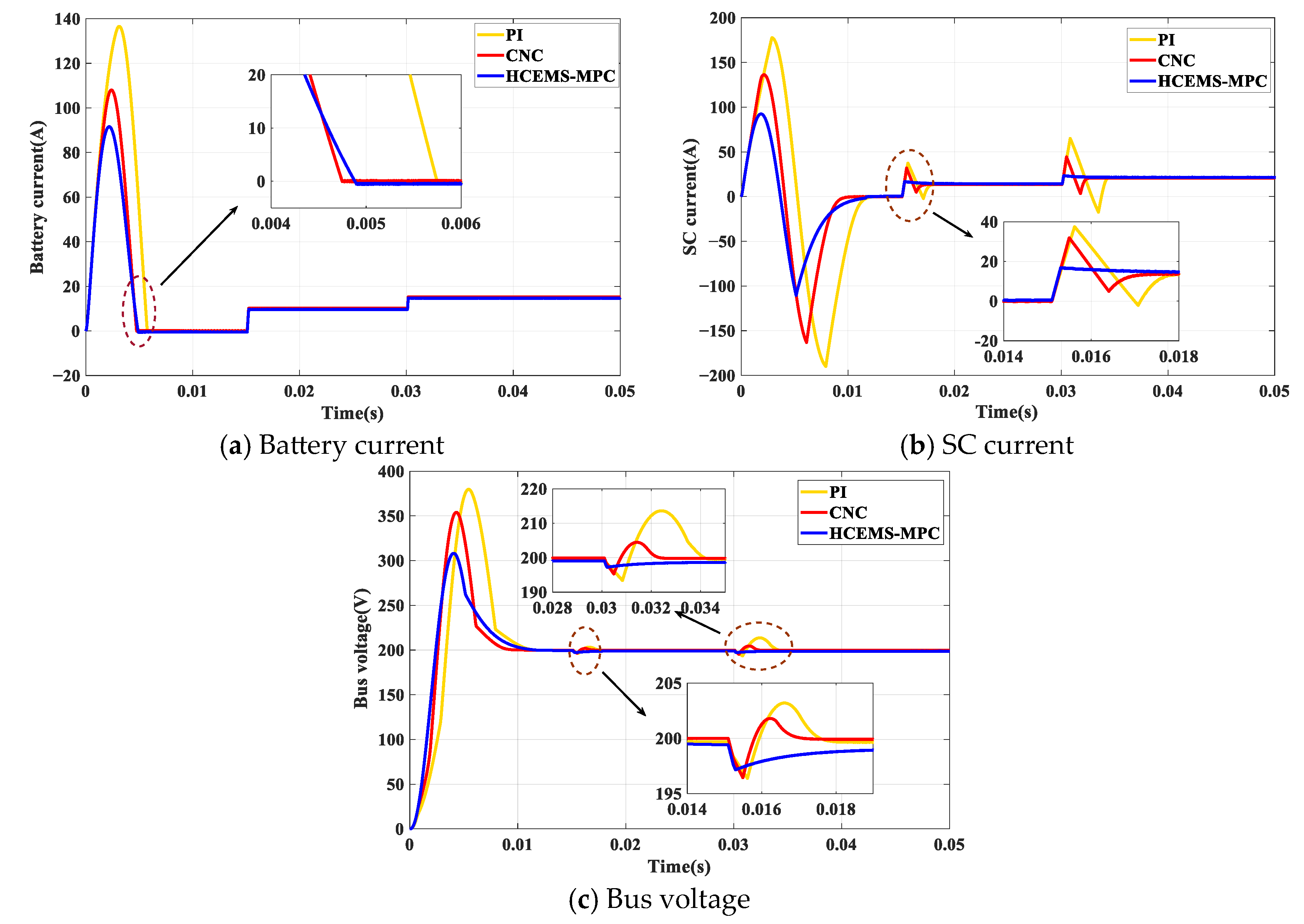
Considering the step change of the load power, the load power Preq is set as 0 W → 4000 W → 6000 W at the times 0 s, 0.015 s, and 0.03 s, respectively. Figure 6a shows the battery current response under the three control strategies. It can be seen that all three control strategies can maintain the stable output of the battery current; however, the PI control strategy has a large overshoot followed by the CNC strategy, and the proposed HCEMS-MPC strategy has the least overshoot. Nevertheless, the initial settling time controlled by the CNC is the smallest at about 0.00475 s followed by the proposed HCEMS-MPC strategy at about 0.0049 s, and the initial settlement time controlled by the PI control strategy is the longest at about 0.00575 s. Figure 6b shows the SC current responses under the three control strategies. It can be seen that when the power step changes, the proposed HCEMS-MPC strategy has a faster response speed and a smaller overshoot than the other two strategies. Figure 6c shows the DC bus voltage response under the three control strategies. It can be seen that when the power step changes, bus voltage fluctuation under the HCEMS-MPC strategy is the smallest, the adjustment time is shorter, and the steady state can be reached faster.
To sum up, all three control strategies have certain overshoots during startup. Compared with the PI control strategy and the CNC strategy, the proposed HCEMS-MPC strategy has a better dynamic performance and can respond in real time according to the change in power so as to achieve optimal control.

4.3. The Results under Customized Power Change

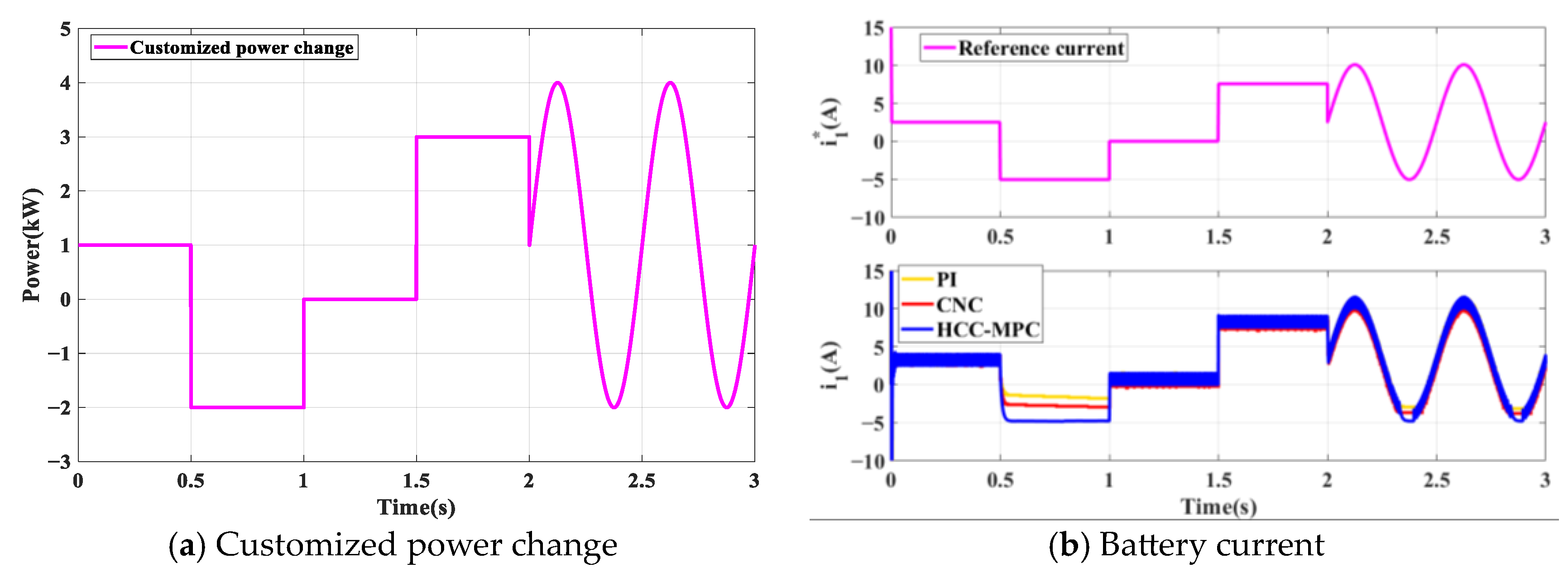
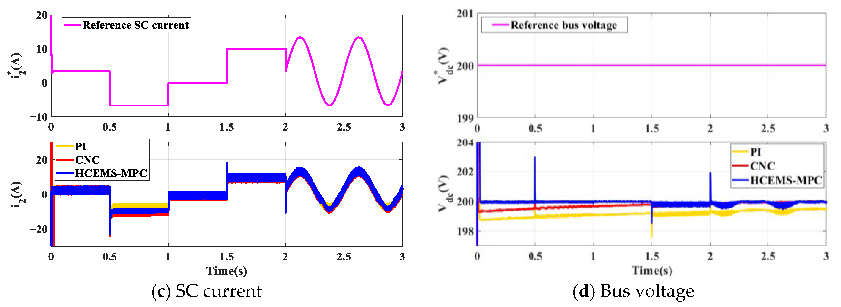
To verify the robustness of the HCEMS-MPC strategy, a sine wave with an amplitude of 3 kw and a frequency of 2 Hz is added between 2 s and 3 s to represent the load power ripple, which is combined with the square wave to form a customized power change as shown in Figure 7a. The battery current i1, SC current i2, and bus voltage Vdc are shown in Figure 7b–d, respectively. It can be seen that when the power fluctuates, both the PI control strategy and CNC strategy have certain errors, and the proposed HCEMS-MPC strategy has the smallest error in current/voltage tracking and can achieve the best control effect among the three strategies.

4.4. The Results under Standard Driving Cycles

In this section, several standard driving cycles, including the Urban Dynamometer Driving Schedule (UDDS), New European Driving Cycle (NEDC), and China Typical Urban Cycle (CTUC), are selected to help analyze the control performance. These driving cycles can better reflect the driving state under real driving conditions.
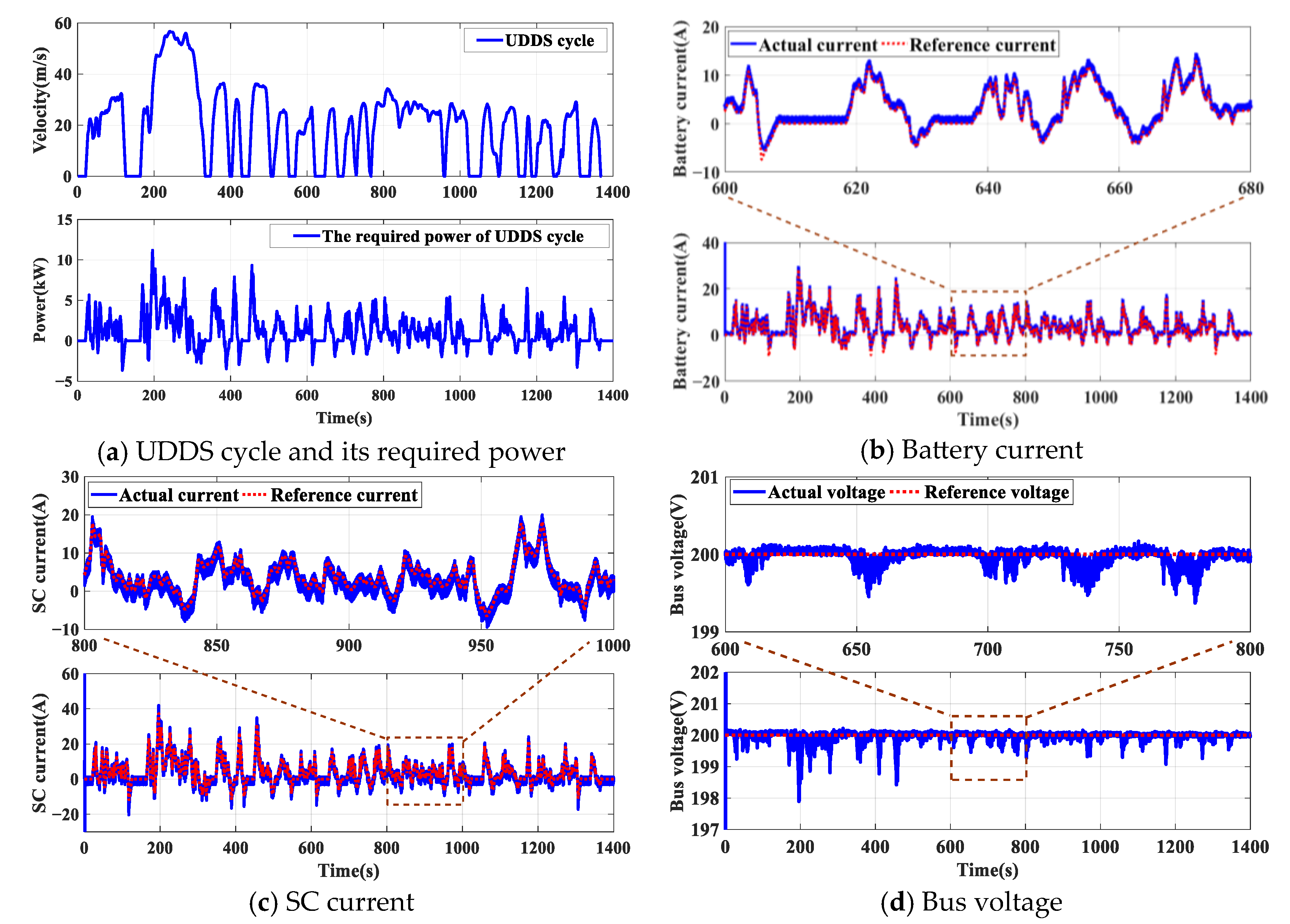
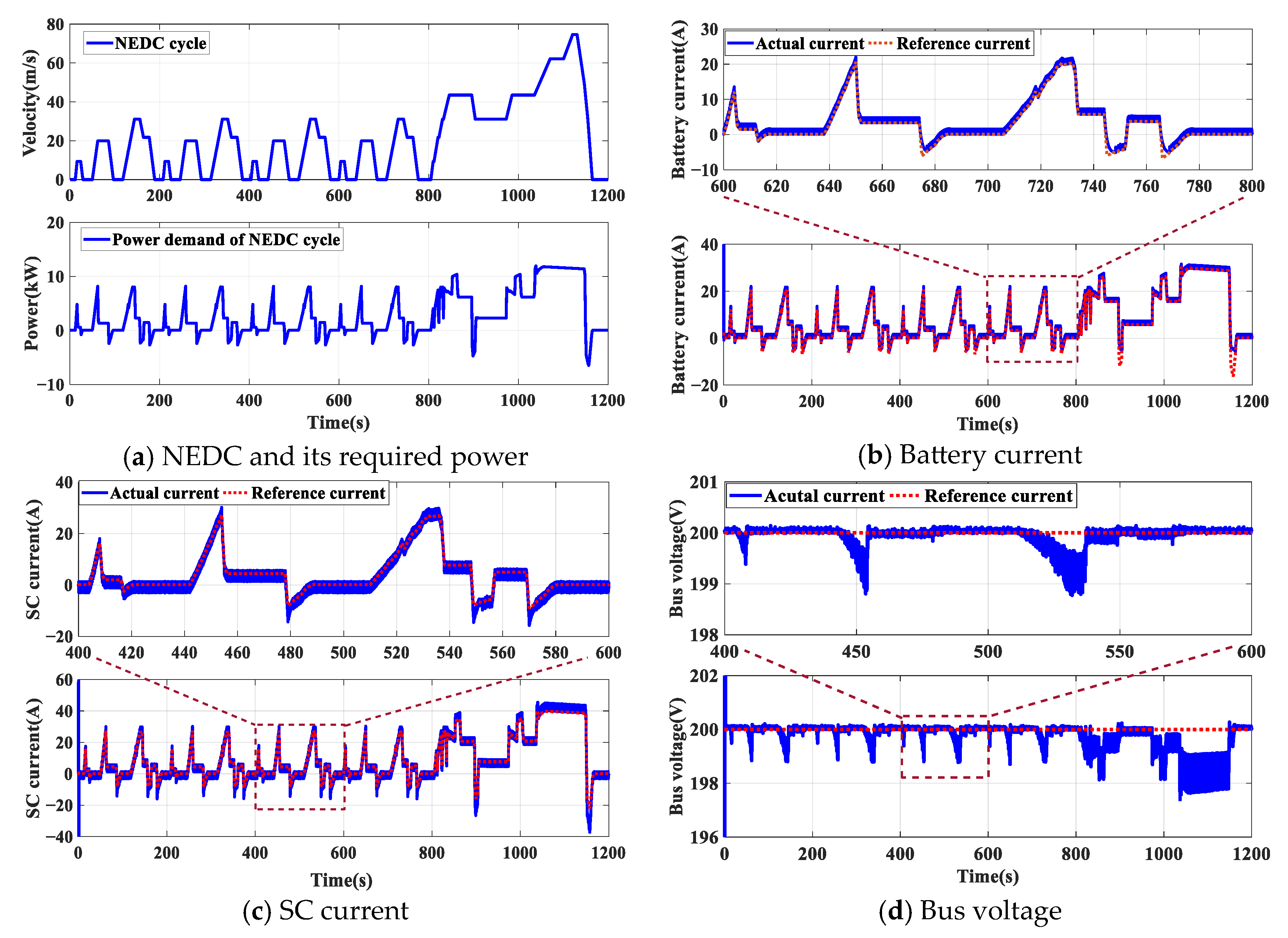
Figure 8a shows the UDDS and its required power. Figure 8b,c show the battery/SC current tracking curve of the UDDS. It can be seen that the battery/SC current can well track the reference value. Figure 8d shows the bus voltage changes. It can be seen that although the bus voltage fluctuates, it is still stable near 200 V, and the maximum error is only 2.1 V. Figure 9a shows the NEDC and its required power. Figure 9b,c show the battery/SC current tracking curve of the NEDC. Figure 9d shows the change in the bus voltage. It can be seen that when power fluctuation is large, the voltage will also fluctuate, but the maximum error is only 2.6 V. Figure 10a shows the CUTC and its required power. Figure 10b,c show the battery/SC current tracking curve of the CUTC. Figure 10d shows the change in the bus voltage, and the maximum error is 8.4 V. To sum up, under the three standard driving cycles, the proposed HCEMS-MPC strategy can achieve accurate power division when the required power changes, can stabilize the output voltage, and can quickly achieve the matching output of the reference current.
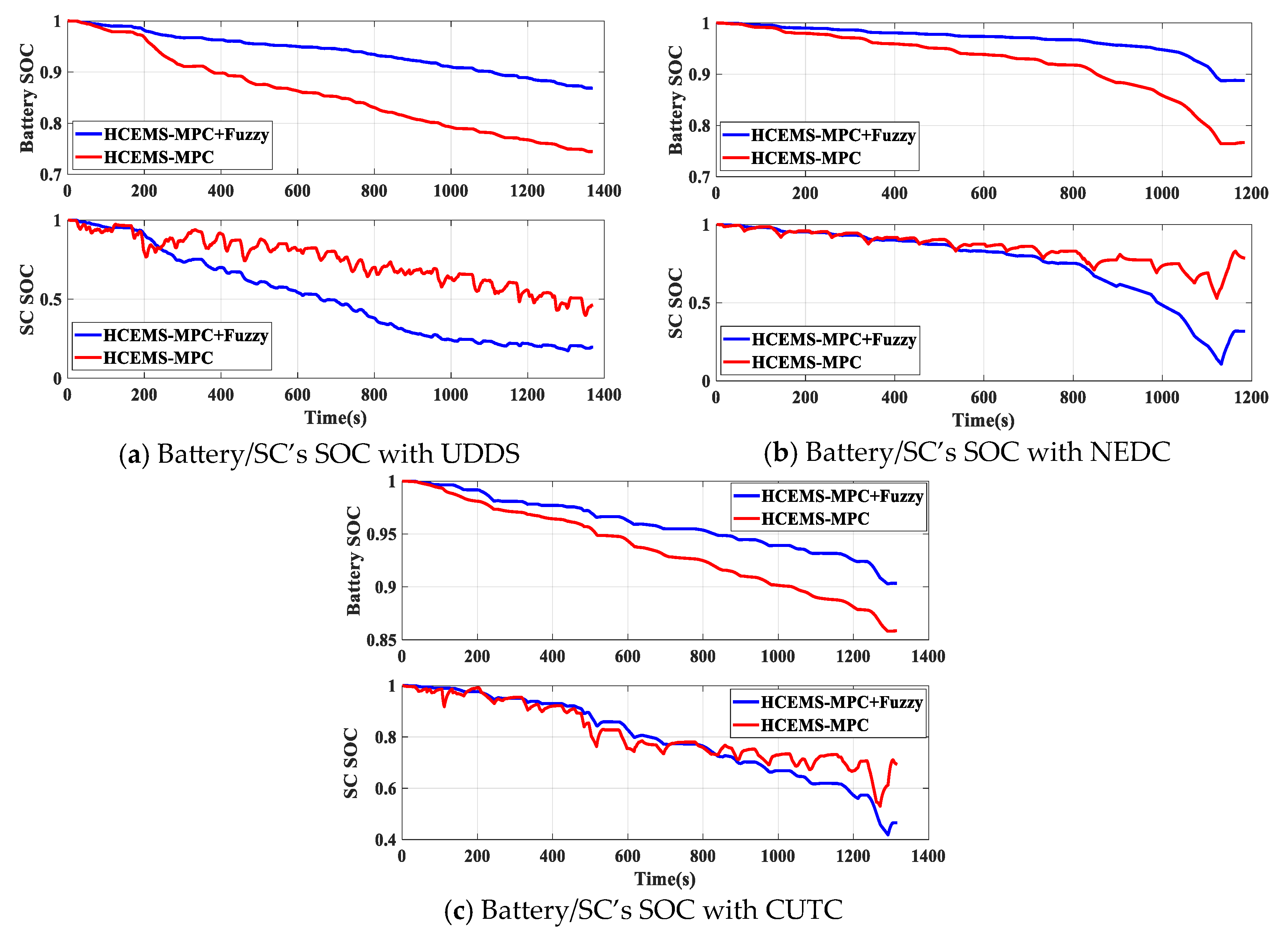
Figure 11a–c and Table 6 show the change in the SOC of the battery and the SOC of the SC before and after the fuzzy EMS is used on the three standard driving cycles (the UDDS, NEDC, and CUTC). After using the fuzzy EMS on the UDDS, the SOC of the battery increases from 0.744 to 0.869, and the SOC of the SC decreases from 0.463 to 0.212. After using the fuzzy EMS on the NEDC, the SOC of the battery increases from 0.766 to 0.887, and the SOC of the SC decreases from 0.784 to 0.317. After using the fuzzy EMS on the CUTC, the SOC of the battery increases from 0.858 to 0.903, and the SOC of the SC decreases from 0.692 to 0.467. It can be seen that the decreasing trend of the SOC of the battery is slower and that the final value significantly increases. The decreasing trend of the SOC of the SC is faster, and the final value significantly decreases, indicating that the SC has taken on more power. Due to factors such as the number of charging and discharging cycles and the degree of deep charging and discharging, which are closely related to the battery life, when the battery’s SOC is maintained at a high level, frequent deep discharging can be avoided, which is beneficial for reducing the battery aging rate and for extending the battery’s service life. At the same time, the slower decreasing trend of the battery’s SOC means that there is an increase in the single-discharge cycle time, which indirectly extends the battery’s service life. These all indicate that the HCEMS-MPC + fuzzy control is effective in extending the battery life.

5. Discussion

In Section 4, the control performance of the proposed HCEMS-MPC strategy was compared with the existing PI and CNC control strategies under the simulation cases of the power step changee and customized power change. The simulation results show that the proposed HCEMS-MPC strategy has a better performance with respect to its fast response and error reduction. At the same time, the four time costs of these three control strategies under the customized power change were calculated as shown in Table 7. It can be seen that PI control has the smallest time cost due to its relatively simple control process. Compared to the CNC strategy, the time cost of the HCEMS-MPC is smaller. Then, the simulations were conducted under three standard driving cycles, and the results showed that the HCEMS-MPC strategy can meet the control requirements under real driving conditions. All of this demonstrates the superiority and effectiveness of the HCEMS-MPC strategy.

6. Conclusions

In this paper, a hierarchical coordinated energy management strategy based on model predictive control (HCEMS-MPC) for the HESS in EVs is proposed, which includes three parts: upper-level energy management based on fuzzy control, a lower-level current predictive control controller, and a lower-level voltage sliding mode controller. The HCEMS-MPC strategy only needs to adjust the weight matrix and the reaching term to avoid complex parameter settings and to reduce the computational complexity. The simulation results under different driving conditions show that the HCEMS-MPC has a better performance with respect to its fast response, error reduction, and robust stability. In addition, considering the SOC of the battery, the SOC decreases more slowly, and the final SOC value significantly increases, thereby extending the single-discharge cycle time of the battery and improving the service life of the battery.

Author Contributions

Conceptualization and methodology, W.H. and Z.L.; software, W.H. and Z.L.; validation, W.H. and Z.L.; writing—original draft preparation, W.H. and Z.L.; writing—review and editing, W.H. and Z.L.; visualization, X.C. and Y.H.; supervision, X.C. and Y.H.; project administration, Z.L. All authors have read and agreed to the published version of the manuscript.

Funding

This work was supported by the National Natural Science Foundation of China (62173134), the Natural Science Foundation of the Hunan Province (2023JJ50029), the Scientific Research Fund of the Hunan Provincial Education Department (22C0435), and the Scientific Research Project of the Hunan Institute of Engineering (21016).

Data Availability Statement

The data presented in this study are available on request from the corresponding author.

Acknowledgments

The authors would like to thank the editor and anonymous reviewers for their patient and valuable comments on this paper.

Conflicts of Interest

The authors declare no conflict of interest.

References

  1. Li, W.; Li, M.; Chen, Z. An Energy Management Strategy for Hybrid Energy Storage Systems coordinate with state of thermal and power. Control. Eng. Pract. 2022, 122, 105122. [Google Scholar]
  2. Salari, O.; Zaad, K.H.; Bakhshai, A.; Jain, P. Reconfigurable Hybrid Energy Storage System for an Electric Vehicle DC–AC Inverter. IEEE Trans. Power Electron. 2020, 35, 12846–12860. [Google Scholar] [CrossRef]
  3. Akar, F.; Tavlasoglu, Y.; Vural, B. An Energy Management Strategy for a Concept Battery/Ultracapacitor Electric Vehicle With Improved Battery Life. IEEE Trans. Transp. Electrif. 2017, 3, 191–200. [Google Scholar] [CrossRef]
  4. Kouchachvili, L.; Yaici, W.; Entchev, E. Hybrid battery/supercpacitor energy storage system for the electric vehicles. J. Power Sources 2018, 374, 237–248. [Google Scholar] [CrossRef]
  5. Song, Z.; Hou, J.; Hofmann, H.; Li, J.; Ouyang, M. Sliding-mode and Lyapunov function-based control for battery/super- capacitor hybrid energy storage system used in electric vehicles. Energy 2017, 122, 601–612. [Google Scholar] [CrossRef]
  6. Liu, Y.; Yang, Z.; Wu, X.; Sha, D.; Lin, F.; Fang, X. An Adaptive Energy Management Strategy of Stationary Hybrid Energy Storage System. IEEE Trans. Transp. Electrif. 2022, 8, 2261–2272. [Google Scholar] [CrossRef]
  7. Song, Z.; Hofmann, H.; Li, J.; Han, X.; Ouyang, M. Optimization for a hybrid energy storage system in electric vehicles using dynamic programing approach. Appl. Energy 2015, 139, 151–162. [Google Scholar] [CrossRef]
  8. Zhang, Q.; Deng, W.; Li, G. Stochastic control of predictive power management for battery/ supercapacitor hybrid energy storage systems of electric vehicles. IEEE Trans. Ind. Inform. 2018, 14, 3023–3030. [Google Scholar] [CrossRef]
  9. Jia, C.; Cui, J.; Qiao, W.; Qu, L. Real-Time Model Predictive Control for Battery- Supercapacitor Hybrid Energy Storage Systems Using Linear Parameter Varying Models. IEEE J. Emerg. Sel. Top. Power Electron. 2021, 11, 251–263. [Google Scholar] [CrossRef]
  10. Song, Z.; Hofmann, H.; Li, J.; Hou, J.; Han, X.; Ouyang, M. Energy management strategies comparison for electric vehicles with hybrid energy storage system. Appl. Energy 2014, 134, 321–331. [Google Scholar] [CrossRef]
  11. Nosrati, K.; Mansouri, H.R.; Saboori, H. Fractional-order PID controller design of frequency deviation in a hybrid renewable energy generation and storage system. CIRED Open Access Proc. J. 2017, 1, 1148–1152. [Google Scholar] [CrossRef]
  12. Xu, D.; Liu, Q.; Yan, W.; Yang, W. Adaptive terminal sliding mode control for hybrid energy storage systems of fuel cell, battery and supercapacitor. IEEE Access 2019, 7, 29295–29303. [Google Scholar] [CrossRef]
  13. Zhang, X.; Lu, Z.; Yuan, X.; Wang, Y.; Shen, X. L2-gain adaptive robust control for hybrid energy storage system in electric vehicles. IEEE Trans. Power Electron. 2020, 36, 7319–7332. [Google Scholar] [CrossRef]
  14. Li, D.; De Schutter, B. Distributed model-free adaptive predictive control for urban traffic networks. IEEE Trans. Control. Syst. Technol. 2021, 30, 180–192. [Google Scholar] [CrossRef]
  15. Dong, H.; Xi, J. Model Predictive Longitudinal Motion Control for the Unmanned Ground Vehicle With a Trajectory Tracking Model. IEEE Trans. Veh. Technol. 2021, 71, 1397–1410. [Google Scholar] [CrossRef]
  16. Saeed, S.; Zhao, W.; Wang, H.; Tao, T.; Khan, F. Fault-tolerant deadbeat model predictive current control for a five-phase PMSM with improved SVPWM. Chin. J. Electr. Eng. 2021, 7, 111–123. [Google Scholar] [CrossRef]
  17. Zheng, L.; Kandula, R.P.; Divan, D. Robust predictive control for modular solid-state transformer with reduced dc link and parameter mismatch. IEEE Trans. Power Electron. 2021, 36, 14295–14311. [Google Scholar] [CrossRef]
  18. Chen, M.; Cheng, Z.; Liu, Y.; Cheng, Y.; Tian, Z. Multitime-scale optimal dispatch of railway FTPSS based on model predictive control. IEEE Trans. Transp. Electrif. 2020, 6, 808–820. [Google Scholar] [CrossRef]
  19. Zhang, X.; Wang, B.; Manandhar, U.; Gooi, H.B.; Foo, G. A model predictive current-controlled bidirectional three-level DC/DC converter for hybrid energy storage system in DC microgrids. IEEE Trans. Power Electron. 2019, 34, 4025–4030. [Google Scholar] [CrossRef]
  20. Chen, S.; Yang, Q.; Zhou, J.; Chen, X. A model predictive control method for hybrid energy storage systems. CSEE J. Power Energy Syst. 2020, 7, 329–338. [Google Scholar]
  21. Zhong, L.; Yin, B.; Liu, W.; Gao, Y.; Zheng, Z.; Li, C.; Ni, F. Research on Model Predictive Controlled HESS for Seamless Mode Switching of DC Microgrid. IEEE Trans. Appl. Supercond. 2021, 31, 1–5. [Google Scholar] [CrossRef]
  22. Morato, M.M.; Normey-Rico, J.E.; Sename, O. Model predictive control design for linear parameter varying systems: A survey. Annu. Rev. Control. 2020, 49, 64–80. [Google Scholar] [CrossRef]
  23. Mayne, D.Q. Model predictive control: Recent developments and future promise. Automatica 2014, 50, 2967–2986. [Google Scholar] [CrossRef]
  24. Lu, Z.; Zhang, X. Composite Non-Linear Control of Hybrid Energy-Storage System in Electric Vehicle. Energies 2022, 15, 1567. [Google Scholar] [CrossRef]
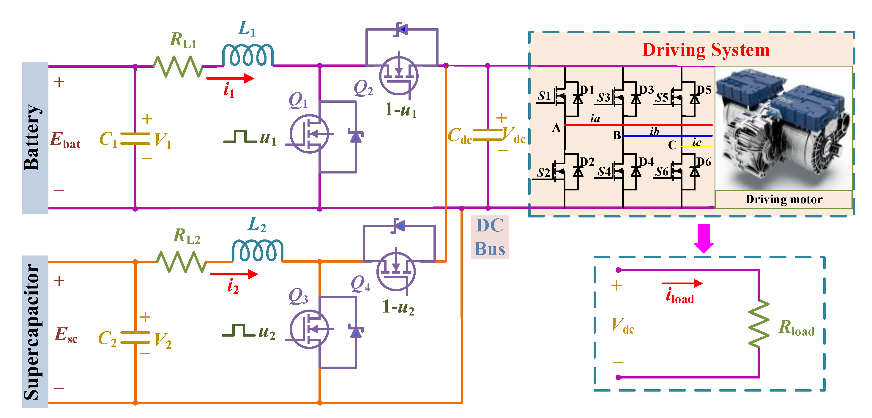
Figure 1. The topology of the battery–SC HESS.
Systems 11 00498 g001
Figure 2. The proposed HCEMS-MPC control strategy.
Systems 11 00498 g002
Figure 3. The membership function of fuzzy variables.
Systems 11 00498 g003
Figure 4. The three-dimensional curved surface diagram of fuzzy rules.
Systems 11 00498 g004
Figure 5. The structure of PI control strategy.
Systems 11 00498 g005
Figure 6. Comparison of three control strategies when power step changes.
Systems 11 00498 g006
Figure 7. Comparison of three control strategies under customized power change.
Systems 11 00498 g007aSystems 11 00498 g007b
Figure 8. Simulation results of UDDS.
Systems 11 00498 g008
Figure 9. Simulation results of NEDC.
Systems 11 00498 g009
Figure 10. Simulation results of CUTC.
Systems 11 00498 g010
Figure 11. The SOC curve before and after fuzzy control.
Systems 11 00498 g011
Table 1. The fuzzy domain and fuzzy language values of fuzzy variables.
Fuzzy variablesPreqSOCbatSOCscKbat
Fuzzy domain[0, 1][0.2, 1][0.1, 1][0, 1]
Fuzzy language valuesS, M, L, TLS, M, LS, M, LS, M, L, TL
Table 2. The fuzzy rules under charging state.
KbatSOCsc
SML
SOCbatSSSM
MSSS
LSSS
Table 3. The fuzzy rules under discharging state.
KbatPreq
SMLTL
SOCbat
(SOCsc = S)
STLLMM
MTLTLLL
LTLTLTLL
SOCbat
(SOCsc = M)
SMSSS
MLMSS
LTLLSS
SOCbat
(SOCsc = L)
SMSSS
MMSSS
LLMSS
Table 4. The three simulation cases.
Simulation CasesSections
1Power step change4.2
2Customized power change4.3
3Standard driving cycle (UDDS, NEDC, CUTC)4.4
Table 5. The parameters of HESS.
ParameterValue
L1: Battery-side inductance (H)2.6 × 10⁻³
L2: SC-side inductance (H)1.8 × 10⁻³
R1: Inductor L1 series resistance(Ω)0.2
R2: Inductor L2 series resistance(Ω)0.15
Cdc: Load-side capacitor (F)1.5 × 10⁻³
C1: Battery-side capacitor (F)0.7 × 10⁻²
C2: SC-side capacitor (F)0.5 × 10⁻²
Table 6. The SOC final value before and after fuzzy control.
UDDSNEDCCUTC
Before fuzzy controlBattery’s SOC0.7440.7660.858
SC’s SOC0.4630.7840.692
After fuzzy controlBattery’s SOC0.8690.8870.903
SC’s SOC0.2120.3170.465
Table 7. The time costs of three strategies under customized power change.
StrategyFirst
Simulation
Second SimulationThird
Simulation
Fourth Simulation
PI31.5931.5731.6131.56
CNC33.6733.7133.6433.66
HCEMS-MPC32.1532.1132.0932.13
Disclaimer/Publisher’s Note: The statements, opinions and data contained in all publications are solely those of the individual author(s) and contributor(s) and not of MDPI and/or the editor(s). MDPI and/or the editor(s) disclaim responsibility for any injury to people or property resulting from any ideas, methods, instructions or products referred to in the content.