Communication

Modular Paradigm for Composites: Modeling Hydrothermal Degradation of Glass Fibers

by
Andrey E. Krauklis
Institute for Mechanics of Materials, University of Latvia, Jelgavas Street 3, 1004 Riga, Latvia
Fibers 2021, 9(12), 83; https://doi.org/10.3390/fib9120083
Submission received: 22 October 2021 / Revised: 22 November 2021 / Accepted: 9 December 2021 / Published: 13 December 2021

Abstract

:
Fiber-reinforced composite materials are often used in structural applications in humid, marine, and offshore environments. Superior mechanical properties are compromised by environmental ageing and hydrolytic degradation. Glass fibers are the most broadly used type of fiber reinforcement to date. However, they are also most severely affected by environmental degradation. The glass fiber degradation rates depend on: (1) glass formulation; (2) environmental factors: pH, T, stress; (3) sizing; (4) matrix polymer; (5) fiber orientation and composite layup. In this short review (communication), seven modules within the Modular Paradigm are reviewed and systematized. These modeling tools, encompassing both trivial and advanced formulas, enable the prediction of the environmental ageing of glass fibers, including the kinetics of mass loss, fiber radius reduction, environmental crack growth and loss of strength. The modeling toolbox is of use for both industry and academia, and the Modular Paradigm could become a valuable tool for such scenarios as lifetime prediction and the accelerated testing of fiber-reinforced composite materials.

1. Introduction

1.1. Background and Motivation

Fiber-reinforced polymer composites (FRPs) have gained a lot of use and popularity for the last 50–60 years or so, due to their excellent mechanical properties, such as high modulus and strength, while at the same time being relatively lightweight and relatively corrosion-resistant compared to more traditional structural materials, i.e., aluminium and steel [1,2]. One of the main reasons for such a superior mechanical performance is the synergy between the three microconstituents that make up a composite [1,2].
FRPs are common in structural applications (wind turbines, tethers, repair patches, risers, and ship hulls, etc.), where humid air and water environments are standard, e.g., in wind energy, oil and gas, and marine and offshore applications [3,4,5,6,7,8,9,10,11]. Exposure of FRPs to water molecules leads to environmental or hydrothermal ageing, continuously weakening the composite. The designed lifetime typically tends to be at least 25–30 years or more, meaning long-term exposures [7]. FRPs age environmentally in aqueous and humid environments; their superior mechanical properties are compromised by environmental ageing and hydrolytic degradation [12,13,14,15,16,17,18]. However, the exact reason for their excellent mechanical performance (mentioned in the previous paragraph) is also the complexity of the environmental ageing phenomenon. Molecular mechanisms are explained in more detail in the Modeling section of the manuscript.
Along with the current technological limitations of composite recycling (although the technology is rapidly developing) [19], the environmental durability of FRPs is one of the present limiting factors to the more rapid growth and development of the composite industry [20]. This fact is due to the superior mechanical properties being compromised by the uncertainty of the material interaction with the environment [21]. Modeling can shed light on these questions and solve the problem at hand [10].
In the state of the art, ageing testing programmes are required for the validation and evaluation of the environmental durability of FRPs [10,22]. These testing programmes are usually very long, e.g., year-long, and thus expensive, leading to enormous expenses (and often becoming a “bottleneck” in some composite industrial projects). This aspect slows down the development of novel projects in the composite industry and must be addressed [10,22,23]. The current trend aims to replace the testing, as mentioned earlier, with as much modeling as possible, i.e., numerical, analytical, and multiscale modeling tools [10,22].
FRPs are multiscale materials in nature. They consist of three microconstituents: a polymeric matrix, a fibrous reinforcement, and a multi-component sizing on the surface of the fibers [2,11]. During the manufacture of FRPs, i.e., during Vacuum-Assisted Resin Transfer Moulding (VARTM), the sizing component forms a sizing-rich composite interphase between the matrix and the fibers, chemically and physically bonding them together [2,24]. The sizing promotes hygrothermal resistance, stress transfer, and adhesion between the fibers and the matrix [11,25]. What complicates the understanding and modeling of the ageing of FRPs is that each of the three microconstituents degrades differently and affects the degradation processes of the other two [26].
Echtermeyer et al. proposed a modular multiscale approach to attack the problem systematically, which evolved into the concept of Modular Paradigm [2,27]. The method breaks down a complex FRP ageing process into modules (or subprocesses), grouped by the microconstituents primarily affected by the material–environment interaction (herein termed as the Modular Group). The Modular Paradigm (or modular framework) is schematically shown in Figure 1 [27].
As shown in Figure 1, the proposed modular approach is divided into four sections. Starting from left to right, these sections are Initial, Matrix, Reinforcement, and Interphase, respectively. In the Initial area, relatively trivial engineering tools are included for determining the initial dry properties of composites (for example, void content, etc.). The subsequent three sections relate to the modeling of environmental degradation of individual microconstituents inside the composite. Most of these modules are a result of a Joint Industrial Project “Affordable Composites” by Echtermeyer et al. (Echtermeyer, Krauklis, Gagani, Akulichev, Vedvik, Sæter, Mazan, Mialon, and Monsås) in collaboration with Moslemian, Muliana et al. and Klavins et al. [2,3,10,26,27,28,29,30,31,32,33,34,35,36,37,38,39,40,41,42,43,44,45,46,47]. The respective work [27] stated that the modular methodology is multiscale and scalable, and thus can and should be further expanded. Furthermore, it was clearly stated that “the modular approach presented herein is in no way a complete overview of the whole degradation framework, yet it is a step towards the multiscale modeling paradigm of the composite ageing” [27].
This communication aims to review the Modular Paradigm for composites while attempting to further improve the methodology by systematizing the Modular Groups. As the problem is too extensive for a single manuscript, the Reinforcement Modular Group is addressed herein. Initially, the Reinforcement Modular Group was divided into two distinct modules, including (1) Glass Fiber Dissolution, and (2) Strength Loss. However, this Modular Group is further expanded in this manuscript, shown later in the Modeling section.

1.2. Environmental Ageing of Glass Fibers and Glass-Fiber-Reinforced Polymer Composites
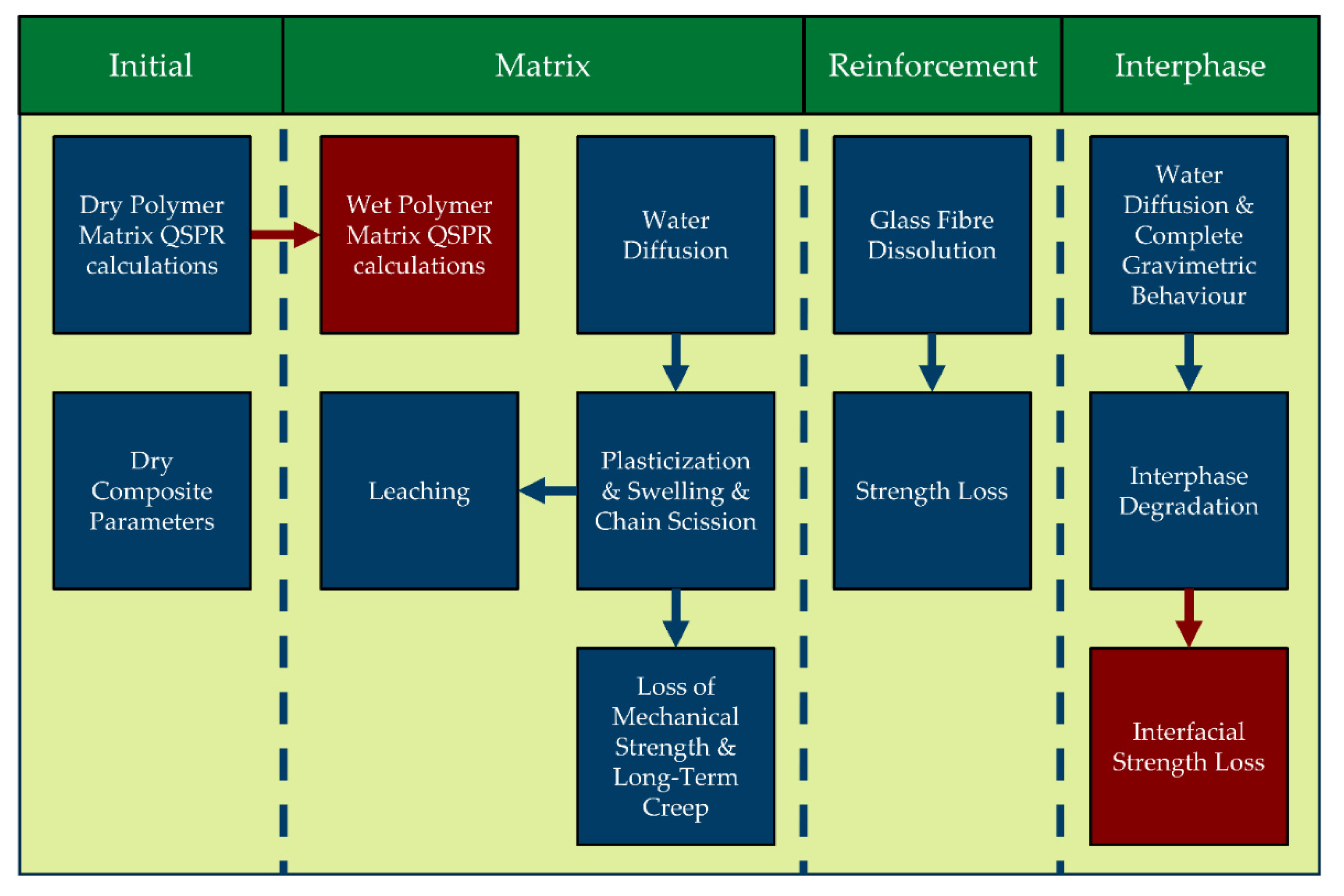
Glass Fibers (GFs) and Carbon Fibers (CFs) are the two most commonly used reinforcement materials in the composite industry as of now. Of the two, GFs are the most broadly used fiber reinforcement to date [19,48,49].
CFs are inert in water and toluene (one of the oil compounds), whereas GFs are inert in toluene but not in water [37]. Furthermore, they are the most affected by environmental ageing, and GFs degrade strongly in water [2]. Therefore, hydrolytic degradation of GFs is significant and is the most common (and critical) type of environmental ageing of the FRP reinforcement microconstituent. Understanding and modeling environmental ageing are essential for GFRPs, since the GFs are hydrophilic [50].
Different types of GFs degrade at different rates, and these rates also depend on such environmental factors as temperature, pH, and stress (via the stress-corrosion mechanism) [36]. Additionally, added protection by sizing and polymeric matrix plays a role in the environmental ageing of GFs [41]. For instance, the dissolution of sized R-glass fibers is ~6 times slower than that of desized R-glass fibers [2,41]. It seems that composite layup and fiber orientation also play a role [2,41]. More details about the modeling of the environmental ageing of GFs are provided in the next chapter on Modeling.

2. Modeling

This manuscript aims to systematize the modeling tools (both trivial and advanced) within the Modular Paradigm that enable prediction of the environmental ageing of glass fibers, including such properties as mass loss, fiber radius reduction, environmental crack growth, and loss of strength. Furthermore, modules that help to identify initial parameters of fibers, fiber bundles, and GFRPs are provided. Individual subchapters are devoted to each of these properties. The seven developed modules of the Reinforcement Modular Group within the Modular Paradigm are presented in Figure 2 (divided into three Dry Property Modules and four Degradation Modules).

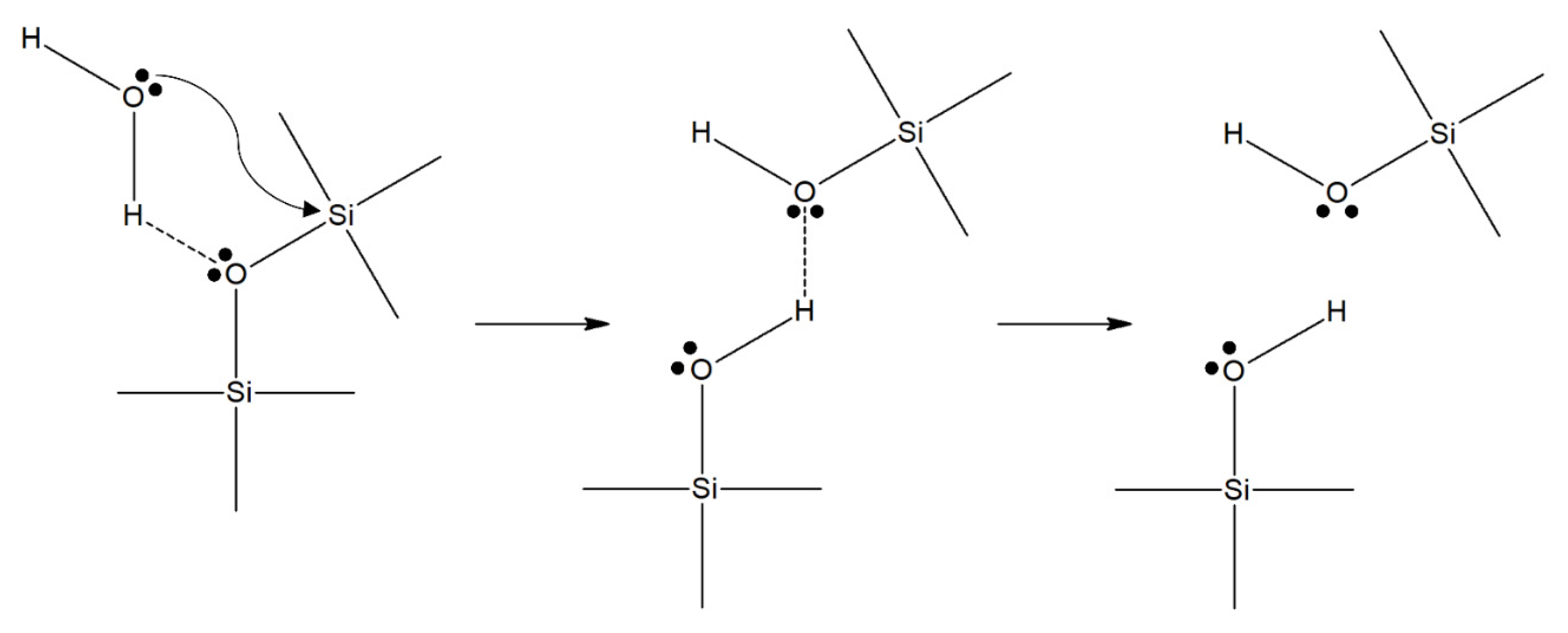
2.1. Molecular Mechanism and Chemical Kinetics of Environmental Ageing

The degradation occurs in two phases: an initial disorderly Phase I, and a subsequent steady-state Phase II. During Phase I [35,36], the complex degradation process involves several simultaneous subprocesses: dissolution and ion-exchange chemical reactions, gel layer formation, and new solid phase formation, e.g., hydroxides [35,51,52,53]. In the long-term Phase II, hydrolytic degradation is governed by the glass dissolution mechanism and follows zero-order reaction kinetics [35,51]. Such kinetics depend on the glass surface area in contact with water, proportional to the fiber radius. As the dissolution continues, the radius decreases, resulting in mass loss deceleration [35].
Competing simultaneous chemical reactions that occur during degradation are Equations (1)–(12), summarized after various sources from 1979 up to 2019 [2,35,36,51,52,53,54,55,56]:
( Si ONa ) + H 2 O ( Si OH ) + OH + Na +
( Si OK ) + H 2 O ( Si OH ) + OH + K +  
( Si O ) 2 Ca + H 2 O 2 ( Si OH ) + 2 OH + Ca 2 +
( Si O ) 2 Mg + H 2 O 2 ( Si OH ) + 2 OH + Mg 2 +
( Si O Al = ) + H 2 O ( Si OH ) + ( = Al OH )
( Si O ) 2 Fe + H 2 O 2 ( Si OH ) + 2 OH + Fe 2 +
( Si O ) 3 Fe + H 2 O 3 ( Si OH ) + 3 OH + Fe 3 +
( Si O Si ) + OH ( Si OH ) + ( Si O )
( Si O ) + H 2 O ( Si OH ) + OH
SiO 2 + H 2 O H 2 SiO 3
H 2 SiO 3 + H 2 O H 4 SiO 4
MeCl x H 2 O ( Me x + ) + xCl
Initially, these reactions happen at independent rates (Phase I); later, a single process becomes limiting and dominates the behavior (Phase II). A common limiting reaction during GF degradation is a hydrolytic reaction shown in Figure 3 [36].
The dissolution-driven degradation of GFs is an energy-activated process and thus follows the Arrhenius principle: the rate of dissolution increases as the temperature increases [36]. The rate is also accelerated by mechanical stress due to a stress-corrosion mechanism [37,57]. However, the most dramatic environmental influence on the dissolution rates of GFs is due to the parabolic pH influence. The dissolution rate is slowest at conditions close to neutral, and accelerates towards both acidic and basic ends, especially in highly acidic environments [36].

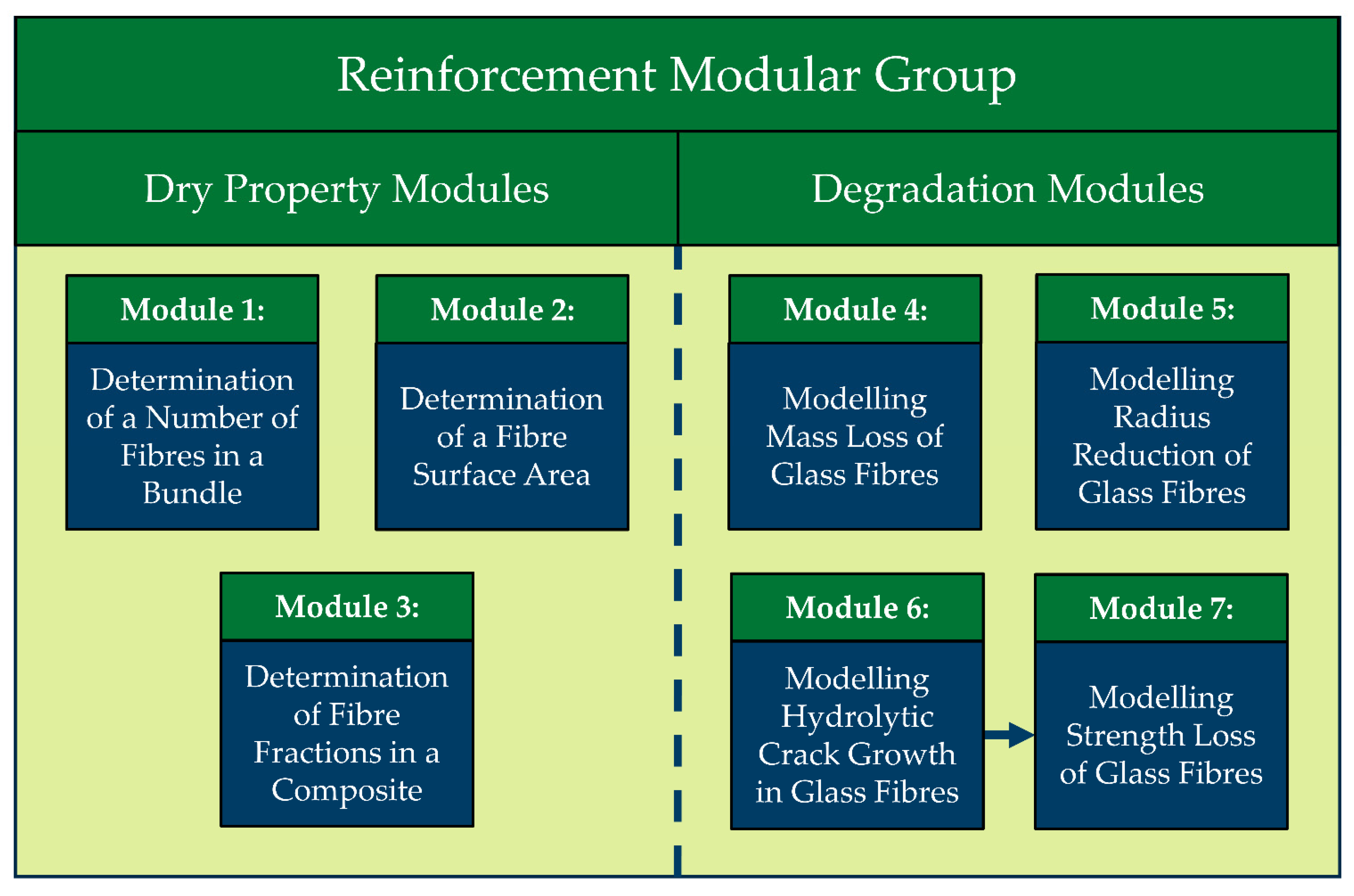
2.2. Module 1: Determination of a Number of Fibers in a Bundle

The total number of GFs in a fiber bundle n can be calculated from density and geometrical considerations, using the following Equation (13):
n = m 0 ρ g l a s s π l r 0 2  
where l is the length of fibers; ρ g l a s s is the density of the glass fiber (not of the bundle); m 0 is the initial mass of a fiber bundle; and r 0 is the initial fiber radius.

2.3. Module 2: Determination of a Fiber’s Surface Area

The external surface area of GFs can be calculated from geometrical considerations as a product of the number, circumference, and length of fibers [2]. The specific surface area of a studied sample can be calculated using the following Equation (14):
S 0 s p e c i f i c = S 0 m 0 = 2 π n l r 0 m 0  
where S 0 s p e c i f i c is the specific surface area of the studied sample; S 0 is the total surface area of glass fibers; m 0 is the initial mass of a fiber bundle; n is the number of glass fibers in a fiber bundle; l is the length of fibers; r 0 is the initial fiber radius.
Alternatively, a Brunauer–Emmett–Teller (BET) method can be applied to experimentally measure the specific surface area of the fibers [2,26].

2.4. Module 3: Determination of Fiber Fractions in a Composite

A composite’s fiber fractions can be determined via density measurements [2,32,34,36] or burnoff tests following the ASTM Standard D3171 [58]. The volumetric and mass fiber fractions can be calculated using the following Equations (15) and (16), respectively:
V f = ρ c o m p o s i t e ρ m ρ f ρ m
m f = ρ f · V f ρ m · ( 1 V f ) + ρ f · V f
where ρ m , ρ f and ρ c o m p o s i t e is the density of matrix polymer, glass fiber, and composite, respectively.

2.5. Module 4: Modeling Mass Loss of Glass Fibers

This module is based on the analytical Dissolving Cylinder Zero-Order Kinetics (DCZOK) model that predicts the GF dissolution kinetics of glass fiber bundles and fiber-reinforced composites at various environmental conditions, described in [35,36,41]. The model differentiates between the complex short-term Phase I, and the dissolution-dominated long-term Phase II. The model can predict the mass loss kinetics during dissolution at both Phases [2].
As was briefly mentioned, the degradation rates depend on: (1) glass chemistry (type of glass fiber); (2) environmental factors (pH, T, stress); (3) presence and type of sizing; (4) presence and type of matrix polymer; (5) fiber orientation and composite layup [2,41]. The dissolution of glass fibers inside the composite is slower than glass fiber bundles not protected by a matrix and is addressed in the analytical model, requiring further improvements [41].
The DCZOK model is deterministic, and all fibers are assumed to have the same initial radius. The cross-sectional surface area at the end of the fibers is considered to be negligible in surface area calculations. The reason is that the length of the fiber in a composite is much longer (millimeter-to-meter scale) than the radius of the fiber (micron scale). Therefore, the added effect of the edges is only in the range of 0.0001–0.1% error; thus, such simplification can be safely made. The length and density of the glass fibers are assumed to be constant during the whole dissolution process.
The mass loss kinetic DCZOK model equation in differential form is the following, as shown in Equation (17) [35]:
m t = 2 n π l ( r 0 K 0 ξ s i z i n g K 0 2 ξ s i z i n g 2 ρ g l a s s t )  
where m is a mass dissolved after time t ; n is the number of fibers; l is the length of fibers; r 0 is the initial fiber radius; ρ g l a s s is the density of glass; K 0 is a dissolution rate constant; ξ s i z i n g is the protective effect of sizing.
Environmental factors, such as acidity, temperature and mechanical stress all affect the material–environment energy-activated interactions, thus affecting the dissolution rate constants K 0 . In a simplified manner, the function is represented by Equation (18):
K 0 = f ( p H , T , σ )
where p H is the acidity, T is the temperature, and σ is the mechanical stress.
Thus, the complete differential DCZOK model can be expanded and written as the following Equations (19) and (20):
m t = 2 n π l ( r 0 K 0 ξ s i z i n g ( K 0 ξ s i z i n g ) 2 ρ g l a s s t )
m t = 2 n π l ( r 0 A e E A ( p H , σ ) R T ξ s i z i n g ( A e E A ( p H , σ ) R T ξ s i z i n g ) 2 ρ g l a s s t )
where A is the pre-exponential factor; R is the gas constant being 8.314 J/(mol∙K); T is the absolute temperature; and E A is the activation energy.
The complete analytical expression of the DCZOK model (Equation (21) is as follows:
{ t t s t :   m d i s s o l v e d = n π l ( 2 r 0 K 0 I t K 0 I   2 ρ g l a s s t 2 )   t > t s t :   m d i s s o l v e d = m d i s s o l v e d t s t + n π l ( 2 r t s t K 0 I I ( t t s t ) K 0 I I   2 ρ g l a s s ( t t s t ) 2 )
where K 0 I and K 0 I I are the rate constants for Phase I and Phase II, respectively; r t s t and m d i s s o l v e d t s t are the fiber radius and lost mass after time t s t when the steady state is reached.

2.6. Module 5: Modeling Radius Reduction of Glass Fibers

This module is based on another expression of the geometrical considerations within the analytical Dissolving Cylinder Zero-Order Kinetics (DCZOK) model that predicts fiber radius reduction kinetics during dissolution, as described in [35,41].
From the geometrical considerations, the volume of a single fiber is π r 2 l , where l is the cylinder length and r is the cylinder radius. For n number of such fibers, the total volume is then n π r 2 l and total mass is ρ g l a s s n π r 2 l . The surface area of a single fiber is 2 π r l . The total surface area for n fibers is 2 n π r l . Expressing mass and surface area in such terms, the following differential Equation (22) is obtained:
r 2 t = 2 K 0 ρ g l a s s r
The analytical DCZOK model equations for radius reduction during Phase I and Phase II are depicted in Equation (23):
{ t t s t :   r = r 0 K 0 I ρ g l a s s t   t > t s t :   r = r t s t K 0 I I ρ g l a s s ( t t s t )
where r is the fiber radius after time t ; r 0 is the initial fiber radius; ρ g l a s s is the density of glass; and K 0 I and K 0 I I are the rate constants for Phase I and Phase II, respectively; r t s t is the fiber radius after time t s t when the steady state is reached.

2.7. Module 6: Modeling Hydrolytic Crack Growth in Glass Fibers

This module is based on another manifestation of the analytical DCZOK model that predicts flaw growth kinetics during the degradation process, described in [36,37].
Mathematically, the time-dependent crack length a ( t ) can be expressed as in Equation (24):
a ( t ) = a 0 + ( d a d t d r d t ) t
where a 0 is the initial crack length, and the time derivatives of a and r stand for the crack growth velocity and the rate of the fiber radius change with time, respectively.
The crack growth velocity undergoes three phases [59]. The first phase is stress intensity factor-dependent, the second is factor-independent, and the third is very rapid. For water-filled cracks, the first phase dominates. According to Freiman, Wiederhorn, and Mecholsky, the crack velocity can be described by Equation (25) [60]:
v = v 0 a H 2 O exp ( G R T )
where v 0 is the velocity-related constant; a H 2 O is the chemical activity of water at the crack tip; G is the activation free energy of the reaction (at the crack tip); R is the gas constant; and T is the absolute temperature. The activation free energy can be expressed in thermodynamic terms as Equation (26) [60]:
G = T S + E + P V ( γ V γ V ) r s u r f a c e
where T is the absolute temperature; S is the activation entropy; E is the activation energy; P is the stress intensity factor-dependent pressure at the crack tip; V is the molar volume of the glass in the activated state ( V stands for the activation volume); γ is the surface tension of the glass in the activated state; γ is the surface tension of the glass; V is the molar volume of the glass; and r s u r f a c e is the radius of the crack tip.
Thus, the velocity is surface radius-dependent and can be expressed by Equation (27):
v = ϑ K 0 ξ s i z i n g ρ g l a s s   ( 27 )
where ϑ is the crack sharpness amplification factor due to the thermodynamics, and K 0 is the kinetic constant of dissolution, which encompasses the energy and entropy terms [37].
Echtermeyer and Krauklis et al. proposed that the crack length is then the initial crack length, and the crack velocity is given by the difference in crack growth and radius shrinkage of the fiber due to dissolution of the glass in water, expressed by Equation (28) [37]:
a ( t ) = a 0 + ( ϑ ξ s i z i n g ) K 0 ρ g l a s s   t
where a is the hydrolytic crack length after an ageing time t ; a 0 is the initial crack length; ϑ is the crack sharpness amplification factor; ρ g l a s s is the density of glass; K 0 is a dissolution rate constant; ξ s i z i n g is the protective effect of sizing.

2.8. Module 7: Modeling Strength Loss of Glass Fibers

Echtermeyer and Krauklis et al. proposed that it should be possible to model the time evolution of GF strength loss using the DCZOK model. Crack growth velocity should be related to a hydrolytic glass degradation rate [35,36] if the kinetic constant of dissolution is known, combined with a single crack sharpness amplification factor   ϑ [37].
The strength reduction model reflects the two-phase behavior and differs from all previously developed empirical models [37]. The model allows temperature and pH dependence predictions on strength loss, as long as dissolution constants can be found. Since the dissolution constants relate to standard Arrhenius-type dependencies, interpolation of measured values can be quickly performed [37].
Linking the strength degradation to the chemical dissolution kinetics at both degradation phases (dissolution constants K 0 I and K 0 I I ) provides a quantitative link. Combining the model of the crack growth kinetics (explained in the previous module) with classic concepts of Griffith and fracture enables the prediction of GF strength with time. The time-dependent strength can also be expressed concerning the static ( t = 0) strength σ ^ f 0 . The strength loss with ageing time can be expressed as Equation (29):
{ t t s t :   σ ^ f ( t ) = σ ^ f 0 1 + K 0 I ( ϑ ξ s i z i n g ) a 0   ρ g l a s s t   t > t s t :   σ ^ f ( t ) = σ ^ f I 1 + K 0 I I ( ϑ ξ s i z i n g ) a 0   ρ g l a s s t  
where σ ^ f is the GF strength after an ageing time t ; σ ^ f 0 is the static strength of GF; σ ^ f I is the GF strength at the end of Phase I or the beginning of Phase II, in other words, i.e., σ ^ f ( t s t ) ; t s t is the time when the steady-state Phase II is reached; K 0 I and K 0 I I are the dissolution kinetics (rate) constants for Phase I and Phase II, respectively; a 0 is the initial crack length; ϑ is the crack sharpness amplification factor due to the thermodynamics; ρ g l a s s is the density of glass; and ξ s i z i n g is the protective effect of sizing.

3. Discussion

3.1. Modeling Issues—Extending to Composites

In composites, polymer matrix and sizing-rich interphase protect the glass and slow dissolution [2]. Quantitative results on how matrix slows down the dissolution are lacking, with the exception of one study on thin composite plates. It was found that even for a few millimeters-thin composite plates, dissolution slows down by about two times when GFs are embedded in a polymer [41]. In addition, it was found that fiber orientation affects the rate of glass dissolution. The dissolution degradation of GFRPs with fibers in a hoop direction, rather than transverse, was the slowest [41].
In the case of composites, a general case of the DCZOK model is required, presented in [2,41]. As the ageing advances, the degradation products are accumulated inside the composite material and subsequently slow down the reaction rate of glass fiber dissolution by shifting the chemical equilibrium. Since the long-term response is governed by Si dissolution [35], the silica hydrolysis products are what causes the deceleration of glass dissolution inside the composites. In the model, the accumulation term accounts for a “driving force” term, which shows that the mass-loss rate is proportional to the difference between concentrations of degradation products inside the composite at saturation and at a specific time point. The global model (general case) can be mathematically expressed as Equation (30) according to [41]:
m t = K 0 ξ s i z i n g S C H 2 O n o r d e r ( C SiO 2 e q C SiO 2 ) m o r d e r
where m   is the total cumulative mass dissolved after time t ; K 0 is the zero-order reaction kinetic constant (see DCZOK modules); ξ s i z i n g is the protective effect of the sizing; S is the glass surface area exposed to water; C H 2 O is the availability of water molecules to the reacting glass surface; n o r d e r is the order of the reaction; C SiO 2 e q is the concentration of degradation products at saturation inside the composite; C SiO 2 is the current concentration of degradation products inside the composite; and m o r d e r is the order of the driving force term.

3.2. Future Work

The Modular Paradigm presented in this work needs more experimental validation with different grades of glass fibers and sizing materials. With different geometries, fiber orientations, and layups of GFRPs, the GF encapsulation’s effect in a GFRP is not fully understood. The Modular Paradigm is not considered complete in the state of the art, yet it is a systematic step forward. Future work should consider the improvement of the individual modules, as well as their interconnectedness. The clear missing link is the lack of understanding of how the time-dependent chemical (hydrolytic) ageing of the interphase results in the deterioration of the composite interfacial strength.
The manuscript provides a short review of fiber-reinforced composite materials (specifically glass fibers) that can be used to predict environmental ageing, including cracks, fractures, strength, and lifetimes. However, the mechanical properties of the fiber-reinforced materials are also greatly dependent on the distribution/geometry of the constitutive matrix and reinforcement phases. Therefore, these aspects have to be addressed in more detail in future works. Some notable works in this area involve findings on interfacial cracks and topology optimization [61], thermal effects [62], fracture strength and toughness [63], and load-bearing ability [64].

4. Conclusions

Seven modules within the Modular Paradigm for modeling the hydrothermal ageing of glass fibers were reviewed and systematized. These modeling tools range from trivial engineering tools to advanced phenomenological formulas. In tandem, they enable the prediction of the environmental ageing of glass fibers, including the kinetics of mass loss, fiber radius reduction, environmental crack growth, and loss of strength. This modeling toolbox provides a systematic approach for predicting the environmental ageing of glass fibers and glass-fiber-reinforced composites, being valuable for both industry and academia. The review evaluated modules that calculate initial parameters such as (1) fiber number in a bundle, (2) fiber surface area, and (3) fiber fractions of a composite, as well as predict (4) mass loss, (5) fiber radius reduction, (6) environmental crack growth, and (7) loss of strength. Limitations of the toolbox and required future work were discussed.

Author Contributions

Conceptualization, A.E.K.; methodology, A.E.K.; software, A.E.K.; validation, A.E.K.; formal analysis, A.E.K.; investigation, A.E.K.; resources, A.E.K.; data curation, A.E.K.; writing—original draft preparation, A.E.K.; writing—review and editing, A.E.K.; visualization, A.E.K.; supervision, A.E.K.; project administration, A.E.K.; funding acquisition, A.E.K. The author has read and agreed to the published version of the manuscript.

Funding

This work was funded by the European Regional Development Fund within the Activity 1.1.1.2 “Post-doctoral Research Aid” of the Specific Aid Objective 1.1.1 of the Operational Programme “Growth and Employment” (Nr.1.1.1.2/VIAA/4/20/606, “Modeling Toolbox for Predicting Long-Term Performance of Structural Polymer Composites under Synergistic Environmental Ageing Conditions”).

Institutional Review Board Statement

Not applicable.

Informed Consent Statement

Not applicable.

Acknowledgments

Andrey is grateful to Echtermeyer for fruitful discussions. Andrey is incredibly grateful to Oksana V. Golubova for her support.

Conflicts of Interest

The authors declare no conflict of interest. The funders had no role in the design of the study; in the collection, analyses, or interpretation of data; in the writing of the manuscript; or in the decision to publish the results.

References

  1. Berg, J.; Jones, F.R. The role of sizing resins, coupling agents and their blends on the formation of the interphase in glass fiber composites. Compos. Part A 1998, 29, 1261–1272. [Google Scholar] [CrossRef]
  2. Krauklis, A.E. Environmental Aging of Constituent Materials in Fiber-Reinforced Polymer Composites. Ph.D. Thesis, NTNU, Trondheim, Norway, 2019; p. 203, ISBN 978-82-326-4027-0. [Google Scholar]
  3. Krauklis, A.; Echtermeyer, A. Mechanism of Yellowing: Carbonyl Formation during Hygrothermal Aging in a Common Amine Epoxy. Polymers 2018, 10, 1017. [Google Scholar] [CrossRef] [Green Version]
  4. Xiao, G.Z.; Shanahan, M.E.R. Swelling of DGEBA/DDA epoxy resin during hygrothermal ageing. Polymer 1998, 39, 3253–3260. [Google Scholar] [CrossRef]
  5. Toscano, A.; Pitarresi, G.; Scafidi, M.; Di Filippo, M.; Spadaro, G.; Alessi, S. Water diffusion and swelling stresses in highly crosslinked epoxy matrices. Polym. Degrad. Stab. 2016, 133, 255–263. [Google Scholar] [CrossRef] [Green Version]
  6. Grabovac, I.; Whittaker, D. Application of bonded composites in the repair of ships structures—A 15-year service experience. Compos. Part A 2009, 40, 1381–1398. [Google Scholar] [CrossRef]
  7. McGeorge, D.; Echtermeyer, A.T.; Leong, K.H.; Melve, B.; Robinson, M.; Fischer, K.P. Repair of floating offshore units using bonded fibre composite materials. Compos. Part A 2009, 40, 1364–1380. [Google Scholar] [CrossRef]
  8. Gustafson, C.G.; Echtermeyer, A. Long-term properties of carbon fibre composite tethers. Int. J. Fatigue 2006, 28, 1353–1362. [Google Scholar] [CrossRef]
  9. Salama, M.M.; Stjern, G.; Storhaug, T.; Spencer, B.; Echtermeyer, A. The First Offshore Field Installation for a Composite Riser Joint; OTC-14018-MS; Offshore Technology Conference: Houston, TX, USA, 2002. [Google Scholar] [CrossRef]
  10. Echtermeyer, A.T.; Gagani, A.I.; Krauklis, A.E.; Mazan, T. Multiscale Modelling of Environmental Degradation—First Steps. In Durability of Composites in a Marine Environment 2. Solid Mechanics and Its Applications; Davies, P., Rajapakse, Y.D.S., Eds.; Springer: Cham, Switzerland, 2018; Volume 245, pp. 135–149. ISBN 978-3-319-65145-3. [Google Scholar]
  11. Thomason, J.L. Glass Fiber Sizings: A Review of the Scientific Literature; Create Space Independent Publishing Platform: Middletown, DE, USA, 2012; ISBN 978-0-9573814-1-4. [Google Scholar]
  12. Weitsman, Y. Coupled damage and moisture-transport in fiber-reinforced, polymeric composites. Int. J. Solids Struct. 1987, 23, 1003–1025. [Google Scholar] [CrossRef]
  13. Weitsman, Y.J.; Elahi, M. Effects of fluids on the deformation, strength and durability of polymeric composites—An overview. Mech. Time-Depend. Mater. 2000, 4, 107–126. [Google Scholar] [CrossRef]
  14. Roy, S. Moisture-Induced Degradation. In Long-Term Durability of Polymeric Matrix Composites; Pochiraju, V.K., Tandon, P.G., Schoppner, A.G., Eds.; Springer: Boston, MA, USA, 2012; pp. 181–236. ISBN 978-1-4419-9307-6. [Google Scholar]
  15. Apicella, A.; Nicolais, L. Effect of Water on the Properties of Epoxy Matrix and Composite. Adv. Polym. Sci. 1985, 72, 69–77. [Google Scholar] [CrossRef]
  16. Lefebvre, D.R.; Elliker, P.R.; Takahashi, K.M.; Raju, V.R.; Kaplan, M.L. The Critical Humidity Effect in the Adhesion of Epoxy to Glass: Role of Hydrogen Bonding. J. Adhes. Sci. Technol. 2000, 14, 925–937. [Google Scholar] [CrossRef]
  17. Guermazi, N.; Elleuch, K.; Ayedi, H.F. The Effect of Time and Aging Temperature on Structural and Mechanical Properties of Pipeline Coating. Mater. Des. 2009, 30, 2006–2010. [Google Scholar] [CrossRef]
  18. Wu, C.F.; Xu, W.J. Atomistic Simulation Study of Absorbed Water Influence on Structure and Properties of Crosslinked Epoxy Resin. Polymer 2007, 48, 5440–5448. [Google Scholar] [CrossRef]
  19. Krauklis, A.E.; Karl, C.W.; Gagani, A.I.; Jørgensen, J.K. Composite Material Recycling Technology—State-of-the-Art and Sustainable Development for the 2020s. J. Compos. Sci. 2021, 5, 28. [Google Scholar] [CrossRef]
  20. Wang, M.; Xu, X.; Ji, J.; Yang, Y.; Shen, J.; Ye, M. The hygrothermal aging process and mechanism of the novolac epoxy resin. Compos. Part B 2016, 107, 1–8. [Google Scholar] [CrossRef]
  21. Halpin, J.C. Effects of Environmental Factors on Composite Materials; Technical Report AFML-TR-67–423; Air Force Materials Laboratory: Dayton, OH, USA, 1969. [Google Scholar]
  22. Krauklis, A.E.; Karl, C.W.; Rocha, I.B.C.M.; Burlakovs, J.; Ozola-Davidane, R.; Gagani, A.I.; Starkova, O. Modelling of Environmental Ageing of Polymers and Polymer Composites—Modular and Multiscale Methods. (soon to be submitted).
  23. Krauklis, A. Predicting environmental ageing of composites: Modular approach & multiscale modelling. In Proceedings of the 1st Corrosion and Materials Degradation Web Conference, Online, 17–19 May 2021; MDPI: Basel, Switzerland, 2021. [Google Scholar] [CrossRef]
  24. Feih, S.; Wei, J.; Kingshott, P.; Sørensen, B.F. The influence of fiber sizing on the strength and fracture toughness of glass fiber composites. Compos. Part A 2005, 36, 245–255. [Google Scholar] [CrossRef]
  25. Loewenstein, K.L. Glass Science and Technology (Book 6), The Manufacturing Technology of Continuous Glass Fibres; Elsevier: Amsterdam, The Netherlands, 1993; ISBN 978-0444893468. [Google Scholar]
  26. Krauklis, A.E.; Gagani, A.I.; Echtermeyer, A.T. Long-Term Hydrolytic Degradation of the Sizing-Rich Composite Interphase. Coatings 2019, 9, 263. [Google Scholar] [CrossRef] [Green Version]
  27. Krauklis, A.E. Environmental Durability of Composite Materials: Analytical Modelling Toolbox. In Aachen Reinforced! Symposium 2021; RWTH: Aachen, Germany, 2021; pp. 62–70. [Google Scholar]
  28. Gagani, A.I. Environmental Effects on Fiber Reinforced Polymer Composites—Fluid and Temperature Effects on Mechanical Performance. Ph.D. Thesis, NTNU, Trondheim, Norway, 2019. ISBN 978-82-326-3839-0. [Google Scholar]
  29. Gagani, A.I.; Fan, Y.; Muliana, A.H.; Echtermeyer, A.T. Micromechanical modeling of anisotropic water diffusion in glass fiber epoxy reinforced composites. J. Compos. Mater. 2017, 52, 2321–2335. [Google Scholar] [CrossRef]
  30. Gagani, A.I.; Echtermeyer, A.T. Influence of delaminations on fluid diffusion in multidirectional composite laminates—Theory and experiments. Int. J. Solids Struct. 2018, 158, 232–242. [Google Scholar] [CrossRef]
  31. Gagani, A.; Krauklis, A.; Echtermeyer, A. Orthotropic fluid diffusion in composite marine structures. Experimental procedure, analytical and numerical modelling of plates, rods and pipes. Comp. Part A 2018, 115, 196–205. [Google Scholar] [CrossRef]
  32. Krauklis, A.E.; Gagani, A.I.; Echtermeyer, A.T. Near-Infrared Spectroscopic Method for Monitoring Water Content in Epoxy Resins and Fiber-Reinforced Composites. Materials 2018, 11, 586. [Google Scholar] [CrossRef] [PubMed] [Green Version]
  33. Krauklis, A.E.; Gagani, A.I.; Echtermeyer, A.T. Hygrothermal Aging of Amine Epoxy: Reversible Static and Fatigue Properties. Open Eng. 2018, 8, 447–454. [Google Scholar] [CrossRef]
  34. Krauklis, A.E.; Gagani, A.I.; Echtermeyer, A.T. Prediction of Orthotropic Hygroscopic Swelling of Fiber-Reinforced Composites from Isotropic Swelling of Matrix Polymer. J. Compos. Sci. 2019, 3, 10. [Google Scholar] [CrossRef] [Green Version]
  35. Krauklis, A.E.; Echtermeyer, A.T. Long-Term Dissolution of Glass Fibers in Water Described by Dissolving Cylinder Zero-Order Kinetic Model: Mass Loss and Radius Reduction. Open Chem. 2018, 16, 1189–1199. [Google Scholar] [CrossRef]
  36. Krauklis, A.E.; Gagani, A.I.; Vegere, K.; Kalnina, I.; Klavins, M.; Echtermeyer, A.T. Dissolution Kinetics of R-Glass Fibres: Influence of Water Acidity, Temperature and Stress Corrosion. Fibers 2019, 7, 22. [Google Scholar] [CrossRef] [Green Version]
  37. Echtermeyer, A.T.; Krauklis, A.E.; Gagani, A.I.; Sæter, E. Zero Stress Aging of Glass and Carbon Fibers in Water and Oil—Strength Reduction Explained by Dissolution Kinetics. Fibers 2019, 7, 107. [Google Scholar] [CrossRef] [Green Version]
  38. Krauklis, A.E.; Akulichev, A.G.; Gagani, A.I.; Echtermeyer, A.T. Time–Temperature–Plasticization Superposition Principle: Predicting Creep of a Plasticized Epoxy. Polymers 2019, 11, 1848. [Google Scholar] [CrossRef] [Green Version]
  39. Gagani, A.; Krauklis, A.; Echtermeyer, A. Anisotropic fluid diffusion in carbon fiber reinforced composite rods: Experimental, analytical and numerical study. Mar. Struct. 2018, 59, 47–59. [Google Scholar] [CrossRef]
  40. Krauklis, A.E.; Gagani, A.I.; Echtermeyer, A.T. Hygrothermal aging of fiber-reinforced composites: Introduction to phenomenological perspective and mass balance approach. In Proceedings of the 21st International Conference on Composite Structures (ICCS21), Bologna, Italy, 4–7 September 2018. [Google Scholar]
  41. Krauklis, A.E.; Echtermeyer, A.T. Dissolving Cylinder Zero-Order Kinetic Model for Predicting Hygrothermal Aging of Glass Fiber Bundles and Fiber-Reinforced Composites. In Proceedings of the 4th International Glass Fiber Symposium, Aachen, Germany, October 2018; Gries, T., Pico, D., Lüking, A., Becker, T., Eds.; pp. 66–72, ISBN 978-3-95886-249-4. [Google Scholar]
  42. Echtermeyer, A.T.; Gagani, A.I.; Krauklis, A.E.; Moslemian, R. Long Term Fatigue Degradation—Superposition of Dry and Wet Properties. In Proceedings of the 22nd International Conference on Composite Materials (ICCM22), Melbourne, Australia, 11–16 August 2019. [Google Scholar]
  43. Gagani, A.I.; Krauklis, A.E.; Sæter, E.; Vedvik, N.P.; Echtermeyer, A.T. A novel method for testing and determining ILSS for marine and offshore composites. Comp. Struct. 2019, 220, 431–440. [Google Scholar] [CrossRef]
  44. Gagani, A.I.; Monsås, A.B.; Krauklis, A.E.; Echtermeyer, A.T. The effect of temperature and water immersion on the interlaminar shear fatigue of glass fiber epoxy composites using the I-beam method. Compos. Sci. Technol. 2019, 181, 107703–107712. [Google Scholar] [CrossRef]
  45. Fan, Y.; Krauklis, A.E.; Gagani, A.; Sæter, E.; Echtermeyer, A.T.; Muliana, A. Predicting Multi-axial Diffusion of Water in Laminated Composite Structural Components. Comp. Struct. 2021, 261, 113551–113562. [Google Scholar] [CrossRef]
  46. Gagani, A.I.; Mialon, E.P.V.; Echtermeyer, A.T. Immersed interlaminar fatigue of glass fiber epoxy composites using the I-beam method. Int. J. Fatigue 2019, 119, 302–310. [Google Scholar] [CrossRef]
  47. Gagani, A.I.; Echtermeyer, A.T. Fluid diffusion in cracked composite laminates–Analytical, numerical and experimental study. Compos. Sci. Technol. 2018, 160, 86–96. [Google Scholar] [CrossRef]
  48. WindEurope—Cefic—EuCIA. Accelerating Wind Turbine Blade Circularity. White Paper. May 2020. Available online: https://windeurope.org/wp-content/uploads/files/about-wind/reports/WindEurope-Accelerating-wind-turbine-blade-circularity.pdf (accessed on 11 November 2020).
  49. Van der Woude, J. (EuCIA) Recycling, Status and Developments in Europe. In International Glass Fiber Symposium; RWTH: Aachen, Germany, 2018. [Google Scholar]
  50. Tournié, A.; Ricciardi, P.; Colomban, P. Glass Corrosion Mechanisms: A Multiscale Analysis. Solid State Ion. 2008, 179, 2142–2154. [Google Scholar] [CrossRef]
  51. Grambow, B.; Müller, R. First-order dissolution rate law and the role of surface layers in glass performance assessment. J. Nucl. Mater. 2001, 298, 112–124. [Google Scholar] [CrossRef]
  52. Grambow, B. A General Rate Equation for Nuclear Waste Glass Corrosion. Mat. Res. Soc. Symp. Proc. 1985, 44, 15–27. [Google Scholar] [CrossRef]
  53. Hunter, F.M.I.; Hoch, A.R.; Heath, T.G.; Baston, G.M.N. Report RWM005105, AMEC/103498/02 Issue 2: Review of Glass Dissolution Models and Application to UK Glasses; AMEC: Didcot, Oxfordshire, UK, 2015. [Google Scholar]
  54. Michalske, T.A.; Freiman, S.W. A Molecular Mechanism for Stress Corrosion in Vitreous Silica. J. Am. Ceram. Soc. 1983, 66, 284–288. [Google Scholar] [CrossRef]
  55. Iler, R.K. The Chemistry of Silica: Solubility, Polymerization, Colloid and Surface Properties and Biochemistry of Silica; Wiley: New York, NY, USA, 1979; p. 896. ISBN 978-0-471-02404-0. [Google Scholar]
  56. Putnis, C.V.; Ruiz-Agudo, E. The mineral–water interface: Where minerals react with the environment. Elements 2013, 9, 177–182. [Google Scholar] [CrossRef]
  57. Krauklis, A. The Effect of Strong Acids on Glass Fibre Reinforced Composites; SINTEF Report 102017059-3-12; SINTEF: Oslo, Norway, 2019. [Google Scholar]
  58. ASTM D3171/D3171-15. Standard Test Methods for Constituent Content of Composite Materials; ASTM: West Conshohocken, PA, USA, 2015. [Google Scholar]
  59. Wierderhorn, S.M.; Bolz, L.H. Stress corrosion and static fatigue of glass. J. Am. Ceram. Soc. 1970, 53, 543–548. [Google Scholar] [CrossRef]
  60. Freiman, S.W.; Wiederhorn, S.M.; Mecholsky, J.J., Jr. Environmentally Enhanced Fracture of Glass: A Historical Perspective. J. Am. Ceram. Soc. 2009, 92, 1371–1382. [Google Scholar] [CrossRef]
  61. Da, D.; Yvonnet, J. Topology Optimization for Maximizing the Fracture Resistance of Periodic Quasi-Brittle Composites Structures. Materials 2020, 13, 3279. [Google Scholar] [CrossRef] [PubMed]
  62. Da, D.; Cui, X.; Long, K.; Cai, Y.; Li, G. Multiscale concurrent topology optimization of structures and microscopic multi-phase materials for thermal conductivity. Eng. Comput. 2019, 36, 126–146. [Google Scholar] [CrossRef]
  63. Da, D.; Qian, X. Fracture resistance design through biomimicry and topology optimization. Extrem. Mech. Lett. 2020, 40, 100890. [Google Scholar] [CrossRef]
  64. Da, D. Topology Optimization Design of Heterogeneous Materials and Structures; John Wiley & Sons: London, UK, 2019; ISBN 978-1786305589. [Google Scholar] [CrossRef]
Figure 1. Modeling toolbox modules for predicting environmental ageing of composites, as shown in the original publication [27]. Blue modules are considered complete (albeit some modifications and improvements are expected), whereas red-colored ones require development. QSPR stands for Quantitative Structure–Property Relationships.
Fibers 09 00083 g001
Figure 2. The seven developed modules of the Reinforcement Modular Group within the Modular Paradigm.
Fibers 09 00083 g002
Figure 3. Hydrolytic degradation reaction of silica glass network, after [36].
Fibers 09 00083 g003
Publisher’s Note: MDPI stays neutral with regard to jurisdictional claims in published maps and institutional affiliations.

