3D-Printed Pseudo Ductile Fiber-Reinforced Polymer (FRP) Composite Using Discrete Fiber Orientations


Abstract
1. Introduction
2. Experimental Procedures
2.1. Materials
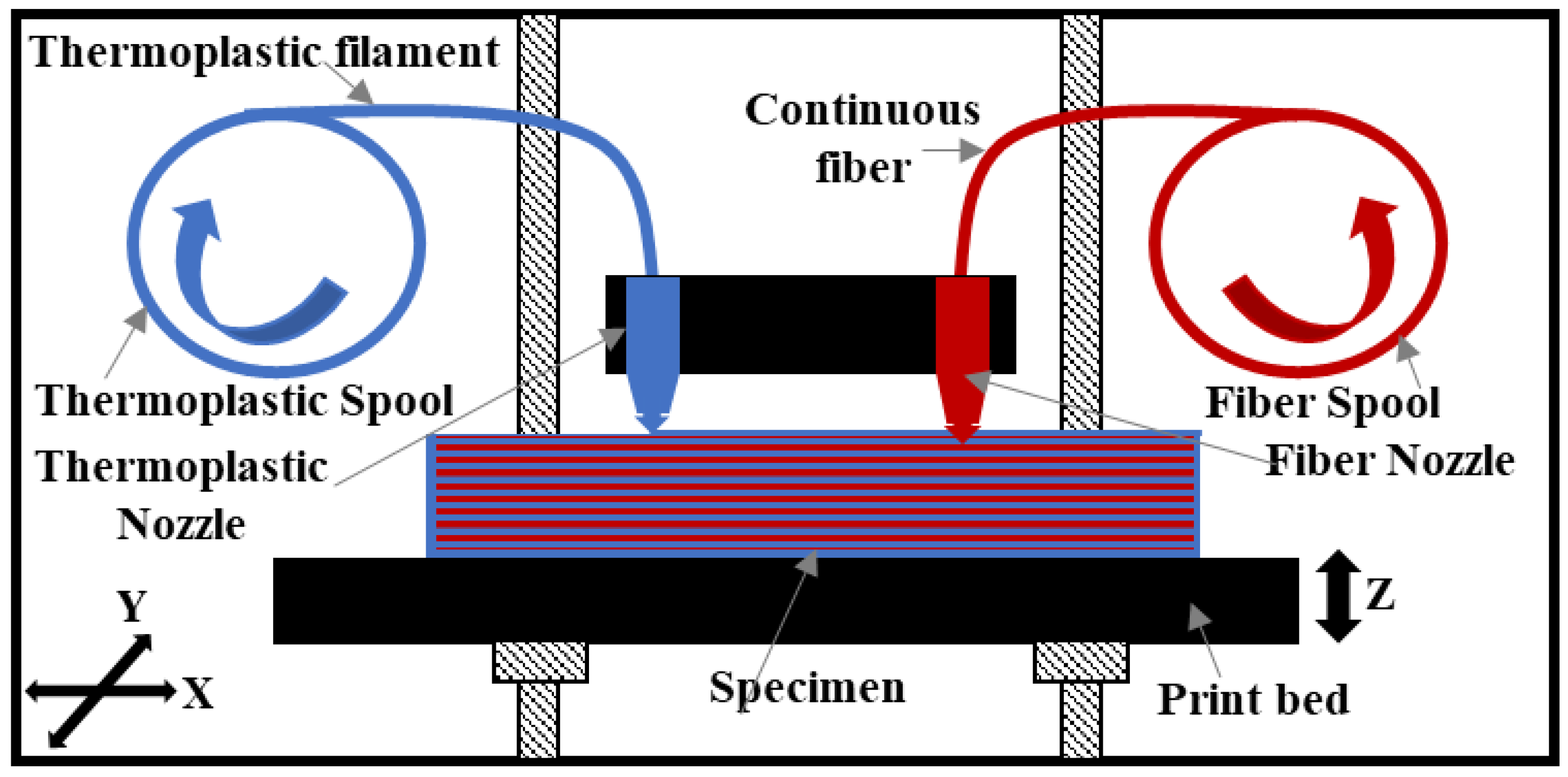
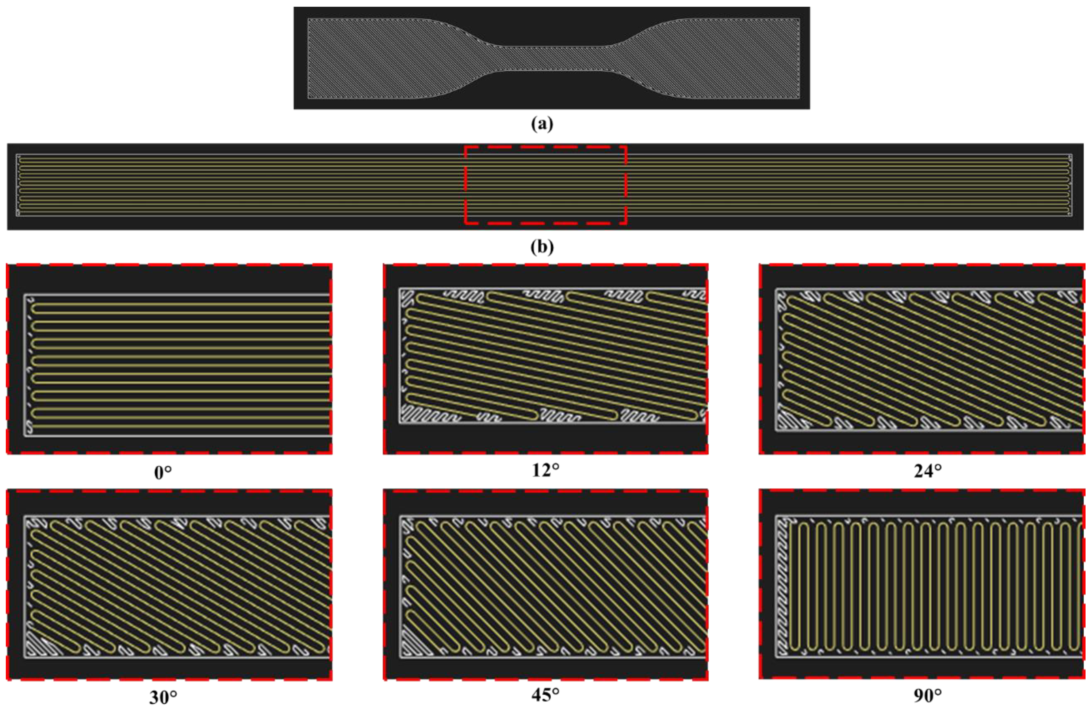
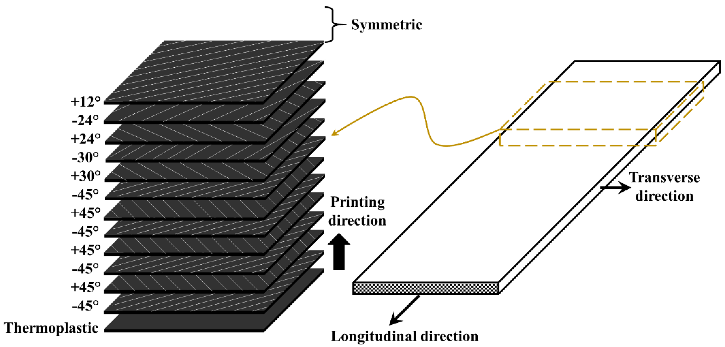
2.2. 3D-Printing and Specimen Preparation
2.3. Static Tension Tests
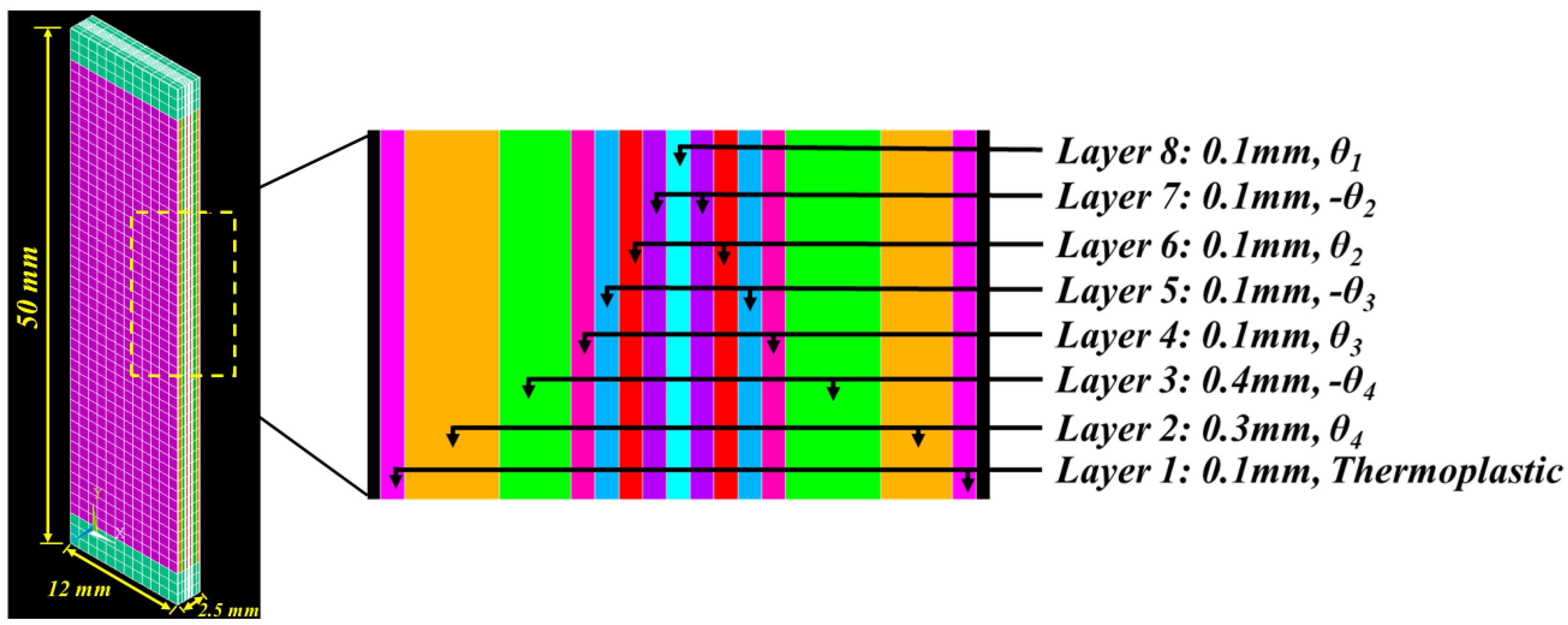
2.4. Finite Element Modeling
3. Results and Discussion
4. Conclusions
5. Patents
Author Contributions
Funding
Acknowledgments
Conflicts of Interest
References
- Bakis, C.E.; Bank, L.C.; Brown, V.; Cosenza, E.; Davalos, J.; Lesko, J.; Machida, A.; Rizkalla, S.; Triantafillou, T. Fiber-reinforced polymer composites for construction—State-of-the-art review. J. Compos. Constr. 2002, 6, 73–87. [Google Scholar] [CrossRef]
- Hollaway, L. A review of the present and future utilisation of FRP composites in the civil infrastructure with reference to their important in-service properties. Constr. Build. Mater. 2010, 24, 2419–2445. [Google Scholar] [CrossRef]
- Pendhari, S.S.; Kant, T.; Desai, Y.M. Application of polymer composites in civil construction: A general review. Compos. Struct. 2008, 84, 114–124. [Google Scholar] [CrossRef]
- Zhao, X.-L.; Zhang, L. State-of-the-art review on FRP strengthened steel structures. Eng. Struct. 2007, 29, 1808–1823. [Google Scholar] [CrossRef]
- Banakar, P.; Shivananda, H.; Niranjan, H. Influence of fiber orientation and thickness on tensile properties of laminated polymer composites. Int. J. Pure Appl. Sci. Technol. 2012, 9, 61. [Google Scholar]
- Swolfs, Y.; Gorbatikh, L.; Verpoest, I. Fibre hybridisation in polymer composites: A review. Compos. Part A Appl. Sci. Manuf. 2014, 67, 181–200. [Google Scholar] [CrossRef]
- Bakis, C.E.; Nanni, A.; Terosky, J.; Koehler, S. Self-monitoring, pseudo-ductile, hybrid FRP reinforcement rods for concrete applications. Compos. Sci. Technol. 2001, 61, 815–823. [Google Scholar] [CrossRef]
- Bunsell, A.; Harris, B. Hybrid carbon and glass fibre composites. Composites 1974, 5, 157–164. [Google Scholar] [CrossRef]
- Czél, G.; Wisnom, M. Demonstration of pseudo-ductility in high performance glass/epoxy composites by hybridisation with thin-ply carbon prepreg. Compos. Part A Appl. Sci. Manuf. 2013, 52, 23–30. [Google Scholar] [CrossRef]
- Jones, K.D.; DiBenedetto, A.T. Fiber fracture in hybrid composite systems. Compos. Sci. Technol. 1994, 51, 53–62. [Google Scholar] [CrossRef]
- Liang, Y.; Sun, C.; Ansari, F. Acoustic emission characterization of damage in hybrid fiber-reinforced polymer rods. J. Compos. Constr. 2004, 8, 70–78. [Google Scholar] [CrossRef]
- Somboonsong, W.; Ko, F.K.; Harris, H.G. Ductile hybrid fiber reinforced plastic reinforcing bar for concrete structures: Design methodology. Mater. J. 1998, 95, 655–666. [Google Scholar]
- Swolfs, Y.; Gorbatikh, L.; Hine, P.; Ward, I.; Verpoest, I. Toughening of Carbon Fibre Composites By Hybridisation with Self-Reinforced Polypropylene. In Proceedings of the 9th International Conference on Composite Science and Technology, Sorrento, Italy, 24–26 April 2013. [Google Scholar]
- Taketa, I.; Ustarroz, J.; Gorbatikh, L.; Lomov, S.V.; Verpoest, I. Interply hybrid composites with carbon fiber reinforced polypropylene and self-reinforced polypropylene. Compos. Part A Appl. Sci. Manuf. 2010, 41, 927–932. [Google Scholar] [CrossRef]
- Ramnath, B.V.; Rajesh, S.; Elanchezhian, C.; Shankar, A.S.; Pandian, S.P.; Vickneshwaran, S.; Rajan, R.S. Investigation on mechanical behaviour of twisted natural fiber hybrid composite fabricated by vacuum assisted compression molding technique. Fibers Polym. 2016, 17, 80–87. [Google Scholar] [CrossRef]
- Singh, J.; Kumar, M.; Kumar, S.; Mohapatra, S. Properties of glass-fiber hybrid composites: A review. Polym. Plast. Technol. Eng. 2017, 56, 455–469. [Google Scholar] [CrossRef]
- Tanwer, A.K. Mechanical properties testing of uni-directional and bi-directional glass fibre reinforced epoxy based composites. Int. J. Res. Advent Technol. 2014, 2, 34–39. [Google Scholar]
- Agarwal, K.; Kuchipudi, S.K.; Girard, B.; Houser, M. Mechanical properties of fiber reinforced polymer composites: A comparative study of conventional and additive manufacturing methods. J. Compos. Mater. 2018, 52, 3173–3181. [Google Scholar] [CrossRef]
- Araya-Calvo, M.; López-Gómez, I.; Chamberlain-Simon, N.; León-Salazar, J.L.; Guillén-Girón, T.; Corrales-Cordero, J.S.; Sánchez-Brenes, O. Evaluation of compressive and flexural properties of continuous fiber fabrication additive manufacturing technology. Addit. Manuf. 2018, 22, 157–164. [Google Scholar] [CrossRef]
- Carey, J.P.; Melenka, G.W.; Schofield, J.; Dawson, M.R.; Cheung, B.O. Evaluation and Prediction of the Tensile Properties of Continuous Fiber-Reinforced 3D Printed Structures. 2016. Available online: https://era.library.ualberta.ca/items/c6f65e7d-3fd0-487d-8bf9-fc0cd8210e9e (accessed on 15 June 2020).
- Elsayed, Y.; Elkholy, A.; Melenka, G.; Kempers, R. Continuous Fiber Polymer Composites for Thermal Applications. In Proceedings of the Canadian Society for Mechanical Engineering International Congress, Toronto, Canada, 27–30 May 2018. [Google Scholar]
- Frketic, J.; Dickens, T.; Ramakrishnan, S. Automated manufacturing and processing of fiber-reinforced polymer (FRP) composites: An additive review of contemporary and modern techniques for advanced materials manufacturing. Addit. Manuf. 2017, 14, 69–86. [Google Scholar] [CrossRef]
- Goh, G.D.; Yap, Y.L.; Agarwala, S.; Yeong, W.Y. Recent progress in additive manufacturing of fiber reinforced polymer composite. Adv. Mater. Technol. 2019, 4, 1800271. [Google Scholar] [CrossRef]
- Gul, J.Z.; Sajid, M.; Rehman, M.M.; Siddiqui, G.U.; Shah, I.; Kim, K.-H.; Lee, J.-W.; Choi, K.H. 3D printing for soft robotics—A review. Sci. Technol. Adv. Mater. 2018, 19, 243–262. [Google Scholar] [CrossRef] [PubMed]
- Mahajan, C.; Cormier, D. 3D printing of carbon fiber composites with preferentially aligned fibers. In Proceedings of the IIE Annual Conference, Nashville, TN, USA, 30 May–2 June 2015; p. 2953. [Google Scholar]
- Tekinalp, H.L.; Kunc, V.; Velez-Garcia, G.M.; Duty, C.E.; Love, L.J.; Naskar, A.K.; Blue, C.A.; Ozcan, S. Highly oriented carbon fiber–polymer composites via additive manufacturing. Compos. Sci. Technol. 2014, 105, 144–150. [Google Scholar] [CrossRef]
- Almutairi, M.D.; Aria, A.I.; Thakur, V.K.; Khan, M.A. Self-Healing Mechanisms for 3D-Printed Polymeric Structures: From Lab to Reality. Polymers 2020, 12, 1534. [Google Scholar] [CrossRef] [PubMed]
- Wang, X.; Jiang, M.; Zhou, Z.; Gou, J.; Hui, D. 3D printing of polymer matrix composites: A review and prospective. Compos. Part B Eng. 2017, 110, 442–458. [Google Scholar] [CrossRef]
- Yang, C.; Tian, X.; Liu, T.; Cao, Y.; Li, D. 3D printing for continuous fiber reinforced thermoplastic composites: Mechanism and performance. Rapid Prototyp. J. 2017, 23, 209–215. [Google Scholar] [CrossRef]
- Melenka, G.W.; Cheung, B.K.; Schofield, J.S.; Dawson, M.R.; Carey, J.P. Evaluation and prediction of the tensile properties of continuous fiber-reinforced 3D printed structures. Compos. Struct. 2016, 153, 866–875. [Google Scholar] [CrossRef]
- Tanikella, N.G.; Wittbrodt, B.; Pearce, J.M. Tensile strength of commercial polymer materials for fused filament fabrication 3D printing. Addit. Manuf. 2017, 15, 40–47. [Google Scholar] [CrossRef]
- ASTM International. D3039/D3039M-14 Standard Test Method for Tensile Properties of Polymer Matrix Composite Materials; ASTM International: West Conshohocken, PA, USA, 2014. [Google Scholar]
- Daniel, I.M.; Ishai, O.; Daniel, I.M.; Daniel, I. Engineering Mechanics of Composite Materials; Oxford University Press: New York, NY, USA, 1994; Volume 3. [Google Scholar]
- ASTM International. D638-14 Standard Test Method for Tensile Properties of Plastics; ASTM International: West Conshohocken, PA, USA, 2014. [Google Scholar]
- Taha, M.R.; Soliman, E.M. Ductile Fiber Reinforced Polymer Plates and Bars Using Monotype Fibers. Google Patents. U.S. Patent 10,337,186, 2 July 2019. [Google Scholar]
- Hyer, M.W.; White, S.R. Stress Analysis of Fiber-Reinforced Composite Materials; DEStech Publications, Inc.: Lancaster, PA, USA, 2009. [Google Scholar]
- Markforged Composite Data Sheet. Available online: http://static.markforged.com/downloads/composites-data-sheet.pdf (accessed on 24 April 2020).
- ASTM International. D3518/D3518M-18 Standard Test Method for In-Plane Shear Response of Polymer Matrix Composite Materials by Tensile Test of a ±45° Laminate; ASTM International: West Conshohocken, PA, USA, 2018. [Google Scholar]
- Godara, A.; Raabe, D. Influence of fiber orientation on global mechanical behavior and mesoscale strain localization in a short glass-fiber-reinforced epoxy polymer composite during tensile deformation investigated using digital image correlation. Compos. Sci. Technol. 2007, 67, 2417–2427. [Google Scholar] [CrossRef]
- Mei, H.; Ali, Z.; Yan, Y.; Ali, I.; Cheng, L. Influence of mixed isotropic fiber angles and hot press on the mechanical properties of 3D printed composites. Addit. Manuf. 2019, 27, 150–158. [Google Scholar] [CrossRef]
- Genedy, M.; Daghash, S.; Soliman, E.; Taha, M.M.R. Improving fatigue performance of GFRP composite using carbon nanotubes. Fibers 2015, 3, 13–29. [Google Scholar] [CrossRef]
- Chennareddy, R.; Tuwair, H.; Kandil, U.F.; ElGawady, M.; Taha, M.R. UV-resistant GFRP composite using carbon nanotubes. Constr. Build. Mater. 2019, 220, 679–689. [Google Scholar] [CrossRef]


| Specimen No. | Specimen Notation | Fiber Orientation | |
|---|---|---|---|
| Layers 2, 4, 6, 8 1 | Layers 3, 5, 7, 9 1 | ||
| 1 | 0° | 0 | 0° |
| 2 | ±12° | 12° | −12° |
| 3 | ±24° | 24° | −24° |
| 4 | ±30° | 30° | −30° |
| 5 | ±45° | 45° | −45° |
| 6 | ±90° | 90° | −90° |
| Notation | Fiber Orientation | Layer Numbers 1 |
|---|---|---|
| −45° | 2, 4, 6, 8, 18, 20, 22, 24 | |
| 45° | 3, 5, 7, 19, 21, 23 | |
| 30° | 9, 17 | |
| −30° | 10, 16 | |
| 24° | 11, 15 | |
| −24° | 12, 14 | |
| 12° | 13 |
| Properties | Specimens | Plastic | |||||
|---|---|---|---|---|---|---|---|
| 0° | ±12° | ±24° | ±30° | ±45° | ±90° | ||
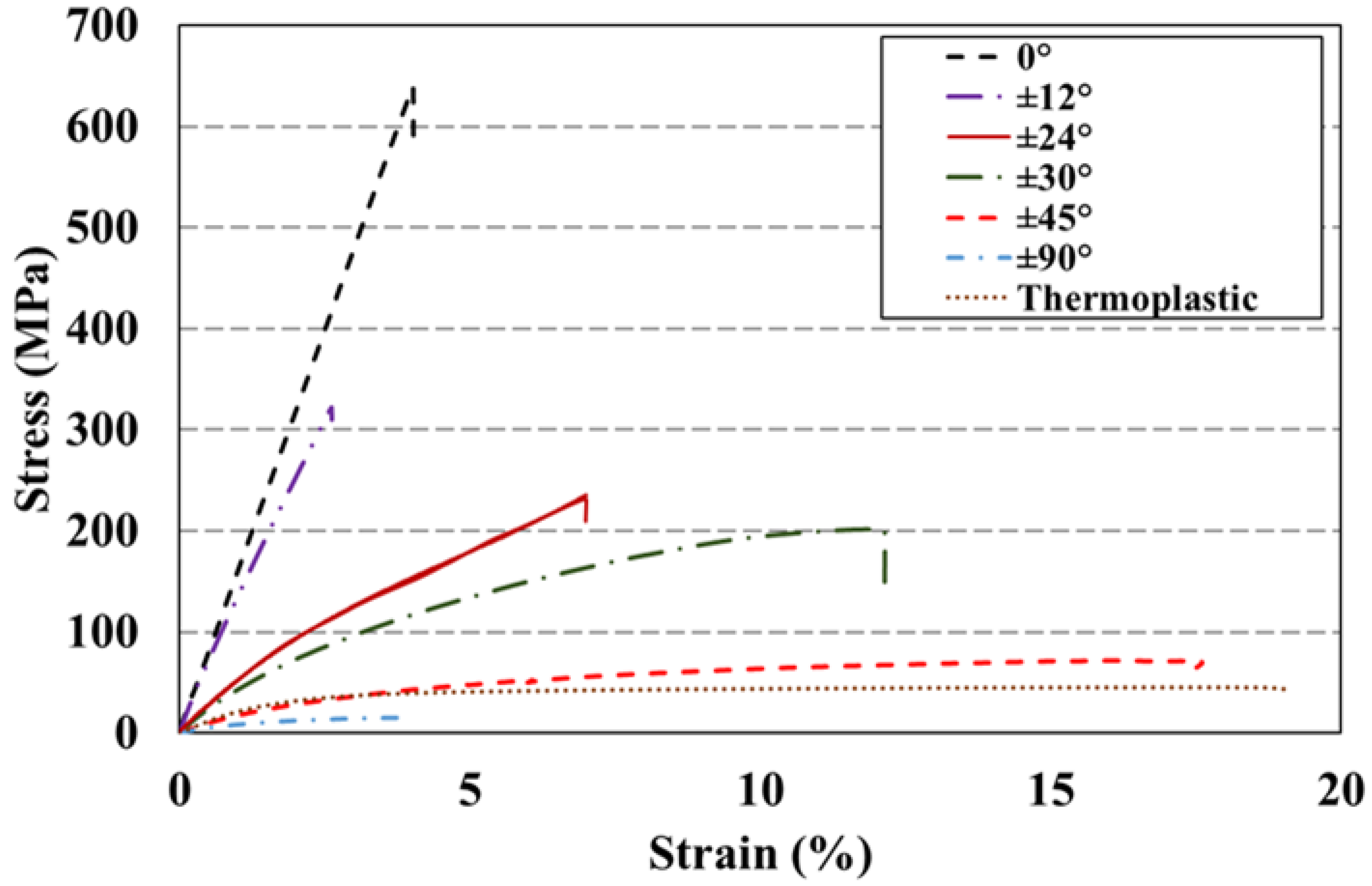
| Strength (MPa) | 623 ± 8.7 | 320 ± 34 | 233 ± 18 | 138 ± 37 | 69 ± 4.9 | 18 ± 2 | 46 ± 0.2 |
| Modulus (GPa) | 16.5 ± 0.45 | 14.85 ± 0.7 | 8 ± 0.4 | 5.4 ± 0.3 | 2 ± 0.2 | 1.9 ± 0.3 | 2.4 ± 0.2 |
| Failure Strain (%) | 3.8 ± 0 | 2.85 ± 0.7 | 7.1 ± 0.14 | 11.2 ± 2.8 | 20 ± 3 | 3.8 ± 0 | 18 ± 1.5 |
| Parameters | Units | Fiber Orientation | |||
|---|---|---|---|---|---|
| ±12° | ±24° | ±30° | ±45° | ||
| Area of 1 layer | mm2 | 1.5 | 1.5 | 1.5 | 1.5 |
| No. of layers | 1 | 4 | 4 | 14 | |
| Total area | mm2 | 1.5 | 6 | 6 | 21 |
| Tangent modulus | GPa | 14.85 | 8 | 5.4 | 2 |
| Axial stiffness (initial) | kN | 22.28 | 48 | 32.40 | 42 |
| Secant modulus | GPa | 13.4 | 5.8 | 3.6 | 1 |
| Axial Stiffness (peak) | kN | 20 | 35.3 | 21.7 | 21 |
| Properties | Specimens | Mean | Standard Deviation | ||||
|---|---|---|---|---|---|---|---|
| 1 | 2 | 3 | 4 | 5 | |||
| Strength (MPa) | 104 | 99.4 | 108.8 | 125 | 116 | 110.6 | 10.1 |
| Modulus (GPa) | 3.6 | 3.1 | 3.0 | 2.9 | 2.7 | 3.05 | 0.34 |
| Failure Strain (%) | 7.8 | 5.8 | 5.7 | 6.8 | 4.8 | 6.18 | 1.1 |
| Elastic | Hill Yield | Failure | |||||||||||
|---|---|---|---|---|---|---|---|---|---|---|---|---|---|
| E11 (GPa) | E22 (GPa) | G12 (GPa) | S11Y (MPa) | S22Y (MPa) | S12Y (MPa) | E11Y (GPa) | E22Y (GPa) | E12Y (GPa) | S11F (MPa) | S22F (MPa) | S12F (MPa) | ||
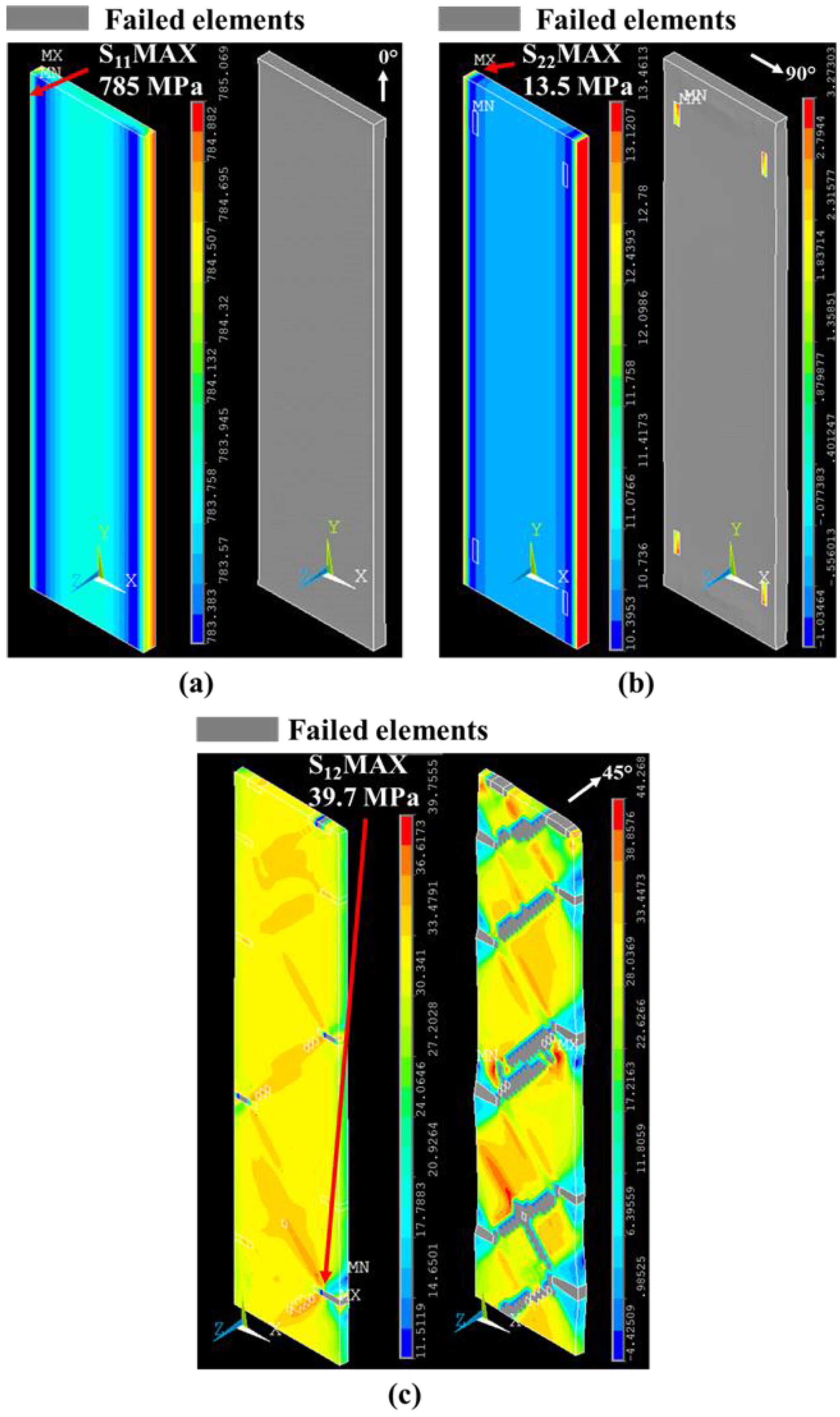
| Fiberglass | 19 | 0.9 | 0.2 | 0.25 | 1000 | 7 | 37 | 15 | 0.2 | 0.1 | 770 | 13 | 40 |
| Plastic | 2.7 | 0.39 | 50 ** | 50 ** | 23 | ||||||||
| Layer Number | Fiber Orientation or Layer Type | Strain (%) | Single-Angled Composite | Multi-Angled Composite | ||
|---|---|---|---|---|---|---|
| Max Stress (MPa) | Min Stress (MPa) | Max Stress (MPa) | Min Stress (MPa) | |||
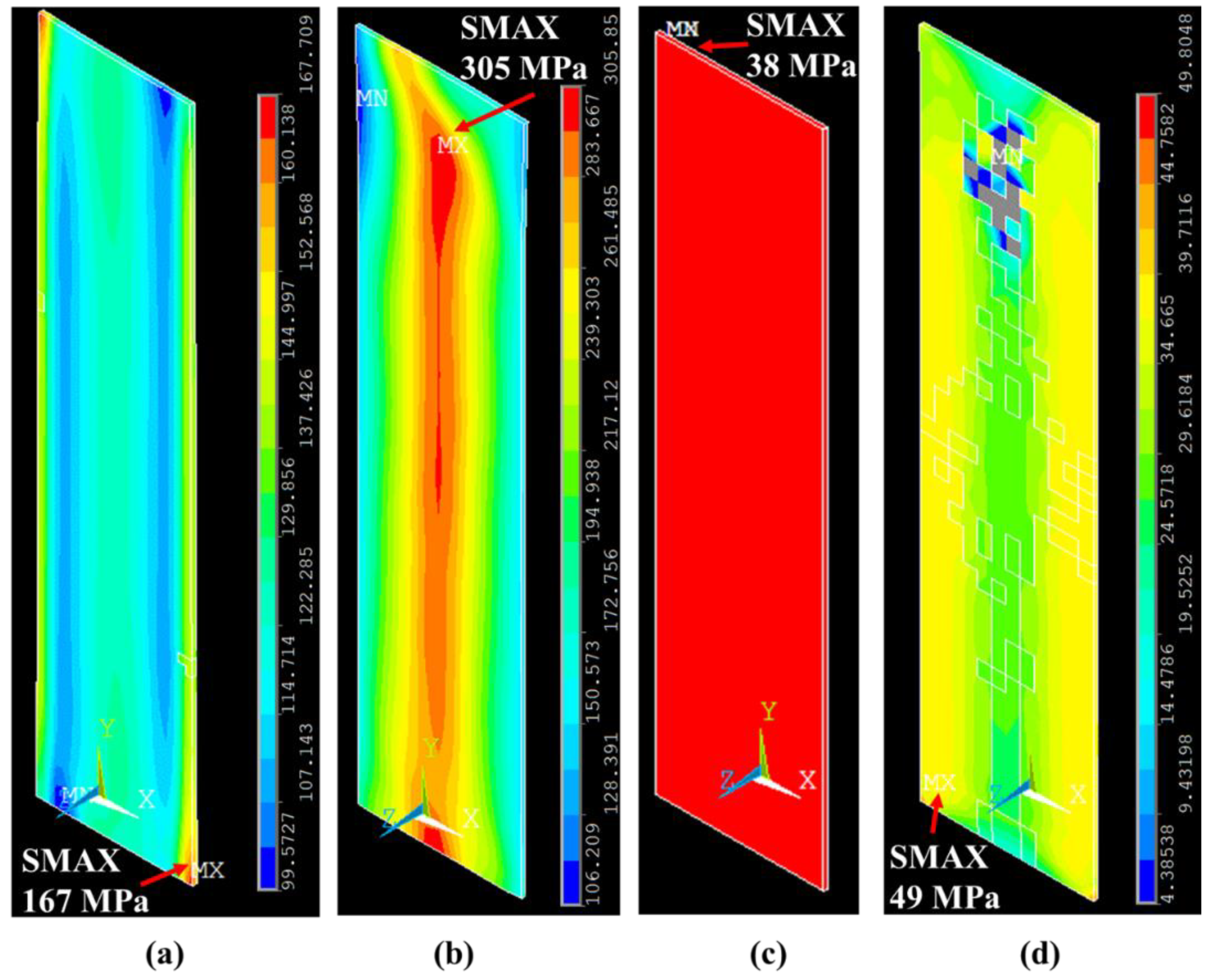
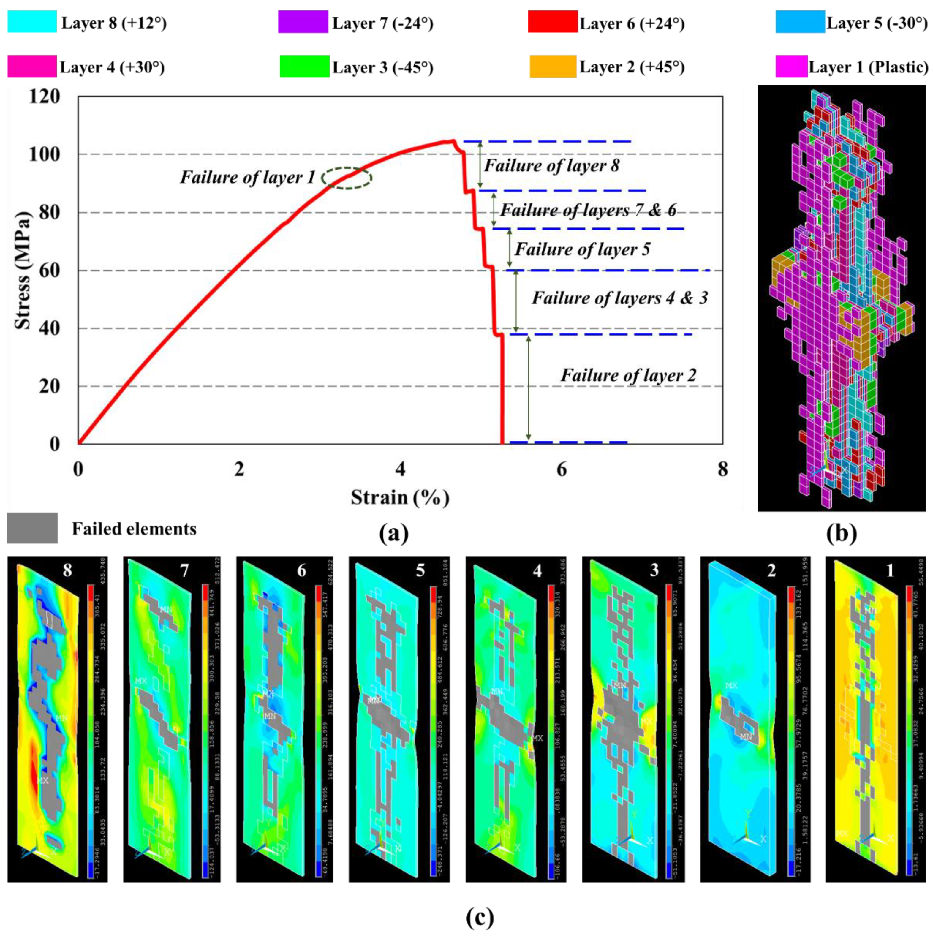
| 8 | +12° | 2.6 | 503 | 279 | 440 | 190 |
| 6 | +24° | 4.5 | 321 | 177 | 396 | 21 |
| 4 | +30 | 4.5 | 167 | 99 | 305 | 106 |
| 2 | +45° | 4.5 | 51 | 28 | 63 | 21 |
| 1 | Thermoplastic | 3.3 | 38 | 38 | 49 | 4 |
© 2020 by the authors. Licensee MDPI, Basel, Switzerland. This article is an open access article distributed under the terms and conditions of the Creative Commons Attribution (CC BY) license (http://creativecommons.org/licenses/by/4.0/).
Share and Cite
Vemuganti, S.; Soliman, E.; Reda Taha, M. 3D-Printed Pseudo Ductile Fiber-Reinforced Polymer (FRP) Composite Using Discrete Fiber Orientations. Fibers 2020, 8, 53. https://doi.org/10.3390/fib8090053
Vemuganti S, Soliman E, Reda Taha M. 3D-Printed Pseudo Ductile Fiber-Reinforced Polymer (FRP) Composite Using Discrete Fiber Orientations. Fibers. 2020; 8(9):53. https://doi.org/10.3390/fib8090053
Chicago/Turabian StyleVemuganti, Shreya, Eslam Soliman, and Mahmoud Reda Taha. 2020. "3D-Printed Pseudo Ductile Fiber-Reinforced Polymer (FRP) Composite Using Discrete Fiber Orientations" Fibers 8, no. 9: 53. https://doi.org/10.3390/fib8090053
APA StyleVemuganti, S., Soliman, E., & Reda Taha, M. (2020). 3D-Printed Pseudo Ductile Fiber-Reinforced Polymer (FRP) Composite Using Discrete Fiber Orientations. Fibers, 8(9), 53. https://doi.org/10.3390/fib8090053