Article

A Moving Interface Finite Element Formulation to Predict Dynamic Edge Debonding in FRP-Strengthened Concrete Beams in Service Conditions

by
Marco Francesco Funari
1,2,*,
Saverio Spadea
2,
Francesco Fabbrocino
3 and
Raimondo Luciano
4
1
Department of Civil Engineering, University of Calabria, 87036 Rende (CS), Italy
2
School of Science and Engineering, University of Dundee, Dundee DD1 4HN, UK
3
Department of Civil Engineering, Pegaso University, 80132 Napoli, Italy
4
Department of Engineering, University of Naples Parthenope, 80132 Napoli, Italy
*
Author to whom correspondence should be addressed.
Fibers 2020, 8(6), 42; https://doi.org/10.3390/fib8060042
Submission received: 28 May 2020 / Revised: 14 June 2020 / Accepted: 19 June 2020 / Published: 24 June 2020

Abstract

:
A new methodology to predict interfacial debonding phenomena in fibre-reinforced polymer (FRP) concrete beams in the serviceability load condition is proposed. The numerical model, formulated in a bi-dimensional context, incorporates moving mesh modelling of cohesive interfaces in order to simulate crack initiation and propagation between concrete and FRP strengthening. Interface elements are used to predict debonding mechanisms. The concrete beams, as well as the FRP strengthening, follow a one-dimensional model based on Timoshenko beam kinematics theory, whereas the adhesive layer is simulated by using a 2D plane stress formulation. The implementation, which is developed in the framework of a finite element (FE) formulation, as well as the solution scheme and a numerical case study are presented.

1. Introduction

Due to their excellent mechanical properties, composite materials are frequently adopted in several engineering fields [1,2]. In civil engineering applications specifically, FRP are largely utilised as internal reinforcement in concrete structures [3,4,5], to fabricate lightweight structural systems [6,7,8,9,10,11,12], and to strengthen existing structural elements [13,14,15,16].
In particular, external strengthening techniques based on FRP systems are adopted in order to retrofit concrete existing structures [17,18]. Typically, such strengthening materials can theoretically provide high performance from a mechanical point of view, although internal defects at the interface level may generate the activation of premature failure mechanisms [19]. Indeed, the interface between the concrete beams and the strengthening element plays a fundamental role in the dynamic response of structural systems. The delamination of the strengthening system may cause substantial reductions in the design load-carrying capacity, and catastrophic failure modes in the structure. One of the most likely failure modes is edge debonding. It may occur under load levels that are below those that drive the structure into the nonlinear range and, in some cases, are still lower than the serviceability limits [18].
Several experimental works have shown the edge debonding mechanism that triggers the immediate failure of the element [20].
However, most of the works present in the literature do not take the dynamic nature of the physical phenomenon into account. In contrast, dynamic effects produced by crack propagation have been extensively investigated in other contexts, in which sophisticated numerical models were adopted. A distinction should be made concerning existing formulations, since explicit [21,22] or implicit [23,24,25] crack representations can be used to simulate interfacial defects. Implicit crack formulations adopt continuum models that are based on constitutive relationships able to predict stiffness reductions.
On the other hand, such a modelling approach is not able to provide detailed information about the dimension of the crack, which is essential to describe fracture phenomena accurately. Moreover, it is unable to capture the formation of the dominant cracks which cause the failure mechanisms. Since refined mesh discretisation is required, explicit approaches are therefore preferred to continuum models.
It is worth noting that explicit approaches require specific formulations and numerical tools to quantify the corresponding fracture parameters. Hence, crack growth can be expressed as a function of fracture mechanic variables such as stress intensity factor or strain energy release rate. As far as the crack length vanishes, the energy release rate( ERR )variable is not defined, and the stresses are not affected by the classical singularity behaviour. However, the inability to reproduce crack initiation can be bypassed by appropriate crack criteria. These may utilise coupled relationships described in terms of energy and stress variables and evaluate the applied loading, crack onset, and evolution. Alternatively, cohesive zone models (CZMs) can provide an easy way to simulate debonding phenomena, including crack onset. In this work, a CZM is adopted to simulate crack evolution for both static and dynamic load conditions. An essential advantage of CZMs is their ability to predict crack onset and propagation directly without introducing pre-existing debonding length. However, the initial finite stiffness may produce, in brittle solids, an excess of compliance, and in those cases in which a high stiffness is introduced, spurious traction oscillations [26]. Such problems may be partially overcome by introducing a very fine discretisation at the crack tip front to obtain a high resolution of the characteristic fracture length of the interface. It is envisaged that the resulting models could be affected by computational complexities because of the large number of variables and non-linearities involved in the interfaces.
As a consequence, in order to avoid some of the issues previously mentioned, numerical models based on moving mesh methodology (a numerical tool widely used in various engineering problems [27,28]) were developed.
Lonetti [29] developed a methodology based on fracture mechanics and moving mesh methodology, which is able to simulate dynamic delamination phenomena in layered structures.
Similarly, a numerical scheme based on a coupled approach between the moving mesh and the cohesive zone modelling was proposed in [30]. In this work, a moving mesh methodology based on an arbitrary Lagrangian–Eulerian (ALE) formulation was introduced in the interface regions, leaving the governing equations of the structural model basically unaltered.
This work is therefore aimed at developing a numerical model based on ALE and CZM to simulate edge debonding on beams strengthened with FRP edge debonding of the adhesive and FRP layers. The numerical formulation was previously proposed to simulate the debonding mechanism of layered and bonded structural members such as composite sandwich structures. The results of such applications were verified against both experimental and numerical results. The generalisation of the method proposed in this paper was applied to concrete beams strengthened in flexure with FRP and subjected to transverse dynamic loading. The work is organised as follows: Section 2 describes the formulation of the model; Section 3 illustrates the outcomes; and some remarkable conclusions are discussed in Section 4.

2. Formulation of the Model

The FRP-strengthened concrete beams were modelled by means of an assembly of layers. The concrete beams, as well as the FRP strengthening, followed a one-dimensional model based on Timoshenko formulation, whereas the adhesive was modelled by using a 2D plane stress formulation (Figure 1).
The materials of each layer were assumed to be linear elastic, and hypotheses concerning small displacements and strains were considered in the analyses. This assumption can be adopted since in more realistic cases the edge debonding precedes severe cracking phenomena as well as material non-linearity in concrete.
As shown in Figure 1, the model was based on two cohesive ALE interface elements which were introduced between adhesive–concrete and adhesive–FRP strip elements. As a consequence, debonding phenomena may affect the layered structures at two different interface levels.
According to ALE methodology, the interfacial crack growth was expressed as a function of two coordinate systems, i.e., referential and moving, which parametrise the motion of the process zone from the onset to crack advancement (Figure 1). From the mathematical point of view, a computational (moving) mesh was implemented as the image of the grid points in the referential (fixed) configuration. In particular, the prescribed motion was expressed in terms of the following Laplace-based equations developed for static (S) or dynamic (D) frameworks [31]:
Δ X , ξ ξ k = 2 Φ k ( ξ , t ) ξ 2   ( S ) Δ X ˙ , ξ ξ k = 3 Φ k ( ξ , t ) t ξ 2 ( D )  
It is worth noting that Equation (1) required boundary and initial conditions (in dynamics), which depend on the motion of the process zone lengths.
At both the interfaces, a traction separation law (TSL) was adopted to simulate triggering and growth of interfacial defects. It is worth noting that the proposed model was quite general and potentially each kind of TSL could be implemented on the moving domain, guaranteeing a refined description of the fracture parameters and the application of cohesive interlinear stresses in the process zone (Figure 1). To reproduce the case study reported in [18], the TSL was taken in agreement with that proposed by Volokh and Needleman [32,33]:
ϕ j ( Δ n j ( x , t ) , Δ t j ( x , t ) ) = ϕ n j + ϕ n j ( 1 + Δ n j ( x , t ) δ n j ) exp ( Δ n j ( x , t ) δ n j Δ t j ( x , t ) 2 δ n j 2 )
where ϕ is the potential function of the cohesive interface, ϕ n is the work of separation per unit area, δ n is a characteristic length parameter of the cohesive interface, x is the longitudinal coordinate along the beam, and t is the time variable.
Furthermore, the subscript j = 1,2 refers to two different cohesive interfaces. The tractions across the cohesive interface are described in the form of nonlinear functions of the displacement discontinuities through the derivatives of the potential:
T n j ( x , t ) = T n j ( Δ n j ( x , t ) , Δ t j ( x , t ) ) = ϕ j Δ n j ( x , t ) = ϕ n j Δ n j ( x , t ) δ n j 2 exp ( Δ n j ( x , t ) δ n j Δ t j ( x , t ) 2 δ n j 2 ) T t j ( x , t ) = T t j ( Δ n j ( x , t ) , Δ t j ( x , t ) ) = ϕ j Δ t j ( x , t ) = 2 ϕ n j Δ t j ( x , t ) δ n j 2 exp ( Δ n j ( x , t ) δ n j Δ t j ( x , t ) 2 δ n j 2 )
The traction separation laws (TSL) for tangential and opening modes, in which the tractions were normalised on their maximum value and the displacements were normalised on the δ n j , are reported in Figure 2. According to the ALE approach, the motion of the crack front was simulated as a rigid displacement of the process zone by introducing the proper boundary conditions (which are not reported for the sake of brevity).
In order to set the motion of the crack front, a proper energy based failure criterion was implemented.
The prescribed mesh motion consisted of the introduction of a rigid displacement at the process zone level ( Ω ). Once the debonding process was started, the tip evolved along the debonding direction.
In order to simulate the moving of the process zone, the following boundary conditions were introduced to simulate the displacements of the process zone:
Ω = X T X ¯ T   with   g f ( X T ) = 0   and   g f ( X ¯ T ) 0 .
Additional details about the mesh motion of the interface region as well as the kinematic formulation of the problem are discussed in [31,34]. The novelty of this research consists in the generalisation and extension of the model to FRP-strengthened concrete beams and the application of the moving mesh methodology for the simulation of edge debonding that can typically occur in such structural elements under dynamic loading.

3. Numerical Implementation

The numerical formulation mentioned earlier was numerically described, taking the form of a set of nonlinear differential equations.
The solution was obtained by using a code written in MATLAB® language [35] which is directly connected to a customised FE subroutine in the framework of COMSOL Metaphysics. A synoptic representation of the proposed algorithm is shown in Figure 3. As extensively described in [31], the model is able to simulate the structural behaviour of FRP-strengthened concrete beams in the serviceability state in both static and dynamic frameworks.
Since the governing equations are intrinsically nonlinear, an incremental–iterative procedure was adopted to evaluate the current solution. The computational algorithm, implemented in the FE environmental program, is extensively described in [36].

4. Results

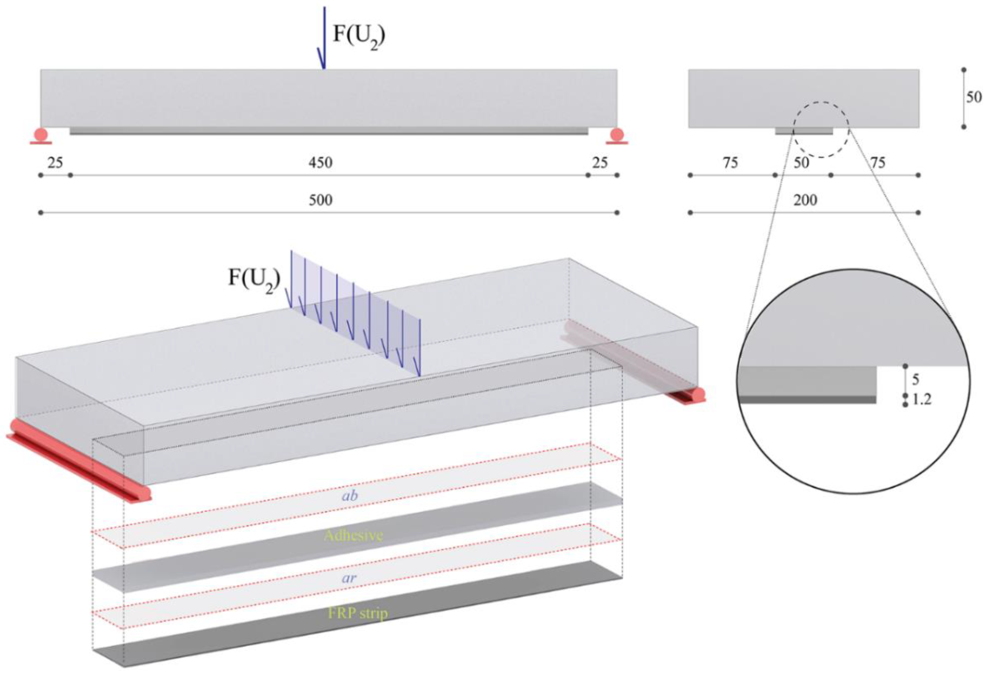
The numerical performance of the proposed model was verified by reproducing a case study investigated by Rabinovitch [18]. The analysis was developed with reference to loading schemes reported in Figure 4, in which the dynamic effects were attributed to the initiation and evolution of the debonding mechanism, whereas the mechanical properties assumed for the strengthened beam as well as those referred to the interfaces were taken in agreement with [18].
As mentioned above, the concrete beams as well as the FRP strengthening were simulated adopting Timoshenko beam elements, whereas the adhesive needed to be simulated by using a 2D plane stress formulation. The numerical discretisation, utilised for the concrete beam as well as for the FRP strip, was assumed to be generally uniform with a length equal to ΔM/L = 5/500 and 5/425, respectively.
Plane stress quadrilateral elements with maximum element length equal to ΔM/L = 5/425 were used to discretise the adhesive layer. On the other hand, a coarse discretisation was adopted at the interfaces, with an exception made for the process zone where a refined mesh was required.
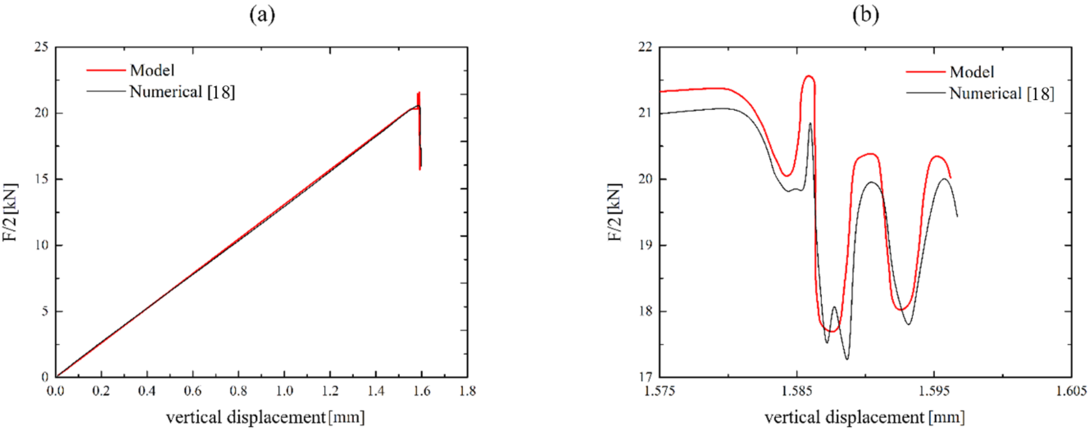
The structure was loaded under a displacement control mode with a loading rate equal to 10 mm/s. However, time steps were varied during the simulation from 1 × 10⁻³ to 1 × 10⁻⁶ s in order to accurately capture the effects produced by crack growth. In Figure 5a, the loading displacement curve is reported.
At first, the FRP-strengthened concrete beams showed a linear elastic branch. Then, an oscillatory and variable behaviour showing a high rate of variability was observed. In Figure 5b, a detail of the resistance curve at the point in which the crack onset is activated is in good agreement with the numerical model developed by Rabinovitch [18]. It is clear that the proposed methodology was able to detect the dynamic nature of the debonding process, as revealed by the oscillations around the new static equilibrium branch.
According to [18], the delamination starts at the adhesive–beam interface; instead, the adhesive–strengthening interface maintains its integrity. Such behaviour is consistent with the debonding mechanism detected in several experimental works [20,37].
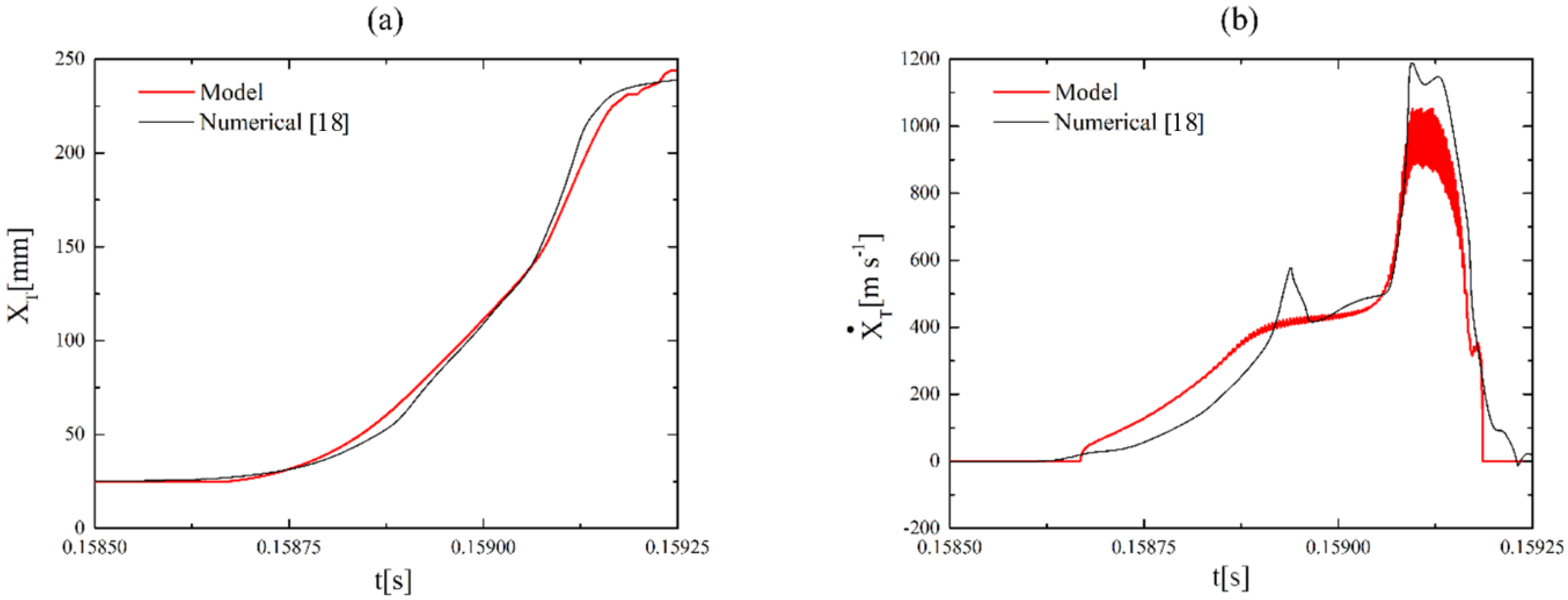
In Figure 6a,b the temporal location and speed of the debonding front of the numerical formulation are compared with that arising from the reference [18]. It is worth noting that the moving mesh approach allows us to simulate the delamination process explicitly by imposing the movement of the process zone. As shown in Figure 6b, the results in terms of crack tip speed are in agreement with the numerical data published in [18]. As a matter of fact, the comparison of the proposed model with those available in the literature demonstrates its ability to describe the behaviour of the dynamic debonding process accurately.

5. Conclusions

Dynamic edge debonding in FRP-strengthened concrete beams was analysed by means of a new numerical model combining moving mesh methodology and CZM. The proposed model was inspired by the authors’ previous work which was developed in the framework of laminate or sandwich structures. The numerical formulation can describe dynamic debonding phenomena just by adopting a proper TSL law at the interface regions. It should be noted that the use of the proposed formulation strongly reduces the computational complexities.
Furthermore, the numerical model is general since it is not dependent on the adopted TSL or the structural formulation. The numerical performance of the proposed model was proved by carrying out a comparison with another numerical model available in the literature.
This denotes computational consistency, accuracy, and robustness.

Author Contributions

M.F.F.: Conceptualization, Methodology, Software, Visualization, Writing—Original draft preparation, Validation, Writing—Reviewing and Editing. S.S.: Methodology, Writing—Original draft preparation. F.F.: Software, Writing—Reviewing and Editing. R.L.: Validation, Writing—Reviewing and Editing. All authors have read and agreed to the published version of the manuscript.

Funding

This research received no external funding.

Conflicts of Interest

The authors declare no conflict of interest.

References

  1. Barbero, E.J. Introduction to Composite Materials Design; CRC Press: Boca raton, FL, USA, 2017. [Google Scholar]
  2. Barbero, E.; Lonetti, P. An Inelastic Damage Model for Fiber Reinforced Laminates. J. Compos. Mater. 2002, 36, 941–962. [Google Scholar] [CrossRef]
  3. Ascione, L.; Razaqpur, A.G.; Spadea, S. Effectiveness of FRP stirrups in concrete beams subject to shear. In Proceedings of the 7th International Conference on FRP Composites in Civil Engineering, CICE, Vancouver, BC, Canada, 20–22 August 2014. [Google Scholar]
  4. Spadea, S.; Orr, J.; Ivanova, K. Bend-strength of novel filament wound shear reinforcement. Compos. Struct. 2017, 176, 244–253. [Google Scholar] [CrossRef] [Green Version]
  5. Spadea, S.; Orr, J.; Nanni, A.; Yang, Y. Wound FRP Shear Reinforcement for Concrete Structures. J. Compos. Constr. 2017, 21. [Google Scholar] [CrossRef] [Green Version]
  6. Ascione, L.; Berardi, V.P.; Giordano, A.; Spadea, S. Macro-scale analysis of local and global buckling behavior of T and C composite sections. Mech. Res. Commun. 2014, 58, 105–111. [Google Scholar] [CrossRef]
  7. Rosa, I.C.; Firmo, J.P.; Correia, J.R.; Mazzuca, P. Influence of elevated temperatures on the bond behaviour of GFRP bars to concrete—Pull-out tests. In IABSE Symposium, Guimaraes 2019: Towards a Resilient Built Environment Risk and Asset Management—Report; International Union of Laboratories and Experts in Construction Materials, Systems and Structures: Guimarães, Portugal, 2019; pp. 861–868. [Google Scholar]
  8. Odessa, I.; Rabinovitch, O.; Frostig, Y. High-order crack propagation in compressed sandwich panels. J. Sandw. Struct. Mater. 2019. [Google Scholar] [CrossRef]
  9. Funari, M.F.; Greco, F.; Lonetti, P. A coupled ALE-Cohesive formulation for interfacial debonding propagation in sandwich structures. Procedia Struct. Integr. 2018, 9, 92–100. [Google Scholar] [CrossRef]
  10. Ascione, L.; Berardi, V.P.; Giordano, A.; Spadea, S. Pre-buckling imperfection sensitivity of pultruded FRP profiles. Compos. Part B Eng. 2015, 72, 206–212. [Google Scholar] [CrossRef]
  11. Razaqpur, A.G.; Ascione, F.; Lamberti, M.; Spadea, S.; Malagic, M. GFRP hollow column to built-up beam adhesive connection: Mechanical behaviour under quasi-static, cyclic and fatigue loading. Compos. Struct. 2019, 224. [Google Scholar] [CrossRef]
  12. Ascione, F.; Lamberti, M.; Razaqpur, A.G.; Spadea, S.; Malagic, M. Pseudo-ductile failure of adhesively joined GFRP beam-column connections: An experimental and numerical investigation. Compos. Struct. 2018, 200, 864–873. [Google Scholar] [CrossRef] [Green Version]
  13. Ombres, L.; Iorfida, A.; Mazzuca, S.; Verre, S. Bond Analysis of Thermally Conditioned FRCM-Masonry Joints; International Measurement Confederation (IMEKO): Budapest, Hungary, 2019. [Google Scholar]
  14. Cascardi, A.; Micelli, F.; Aiello, M.A. FRCM-confined masonry columns: Experimental investigation on the effect of the inorganic matrix properties. Constr Build Mater 2018, 186, 811–825. [Google Scholar] [CrossRef]
  15. Cascardi, A.; Dell’Anna, R.; Micelli, F.; Lionetto, F.; Aiello, M.A.; Maffezzoli, A. Reversible techniques for FRP-confinement of masonry columns. Constr Build Mater 2019, 225, 415–428. [Google Scholar] [CrossRef]
  16. Cascardi, A.; Aiello, M.A.; Triantafillou, T. Analysis-oriented model for concrete and masonry confined with fiber reinforced mortar. Mater Struct 2017, 50. [Google Scholar] [CrossRef]
  17. Ombres, L.; Verre, S. Flexural Strengthening of RC Beams with Steel-Reinforced Grout: Experimental and Numerical Investigation. J. Compos. Constr. 2019, 23. [Google Scholar] [CrossRef]
  18. Rabinovitch, O. Dynamic edge debonding in FRP strengthened beams. Eur. J. Mech. A Solids 2014, 47, 309–326. [Google Scholar] [CrossRef]
  19. Bruno, D.; Greco, F.; Lonetti, P. A fracture-ALE formulation to predict dynamic debonding in FRP strengthened concrete beams. Compos. Part B Eng. 2013, 46, 46–60. [Google Scholar] [CrossRef]
  20. Rabinovitch, O.; Frostig, Y. Experiments and analytical comparison of RC beams strengthened with CFRP composites. Compos. Part B Eng. 2003, 34, 663–677. [Google Scholar] [CrossRef]
  21. Funari, M.F.; Greco, F.; Lonetti, P.; Spadea, S. A numerical model based on ALE formulation to predict crack propagation in sandwich structures. Frat. Ed Integrita Strutt. 2019, 13, 277–293. [Google Scholar] [CrossRef]
  22. Fabbrocino, F.; Funari, M.F.; Greco, F.; Lonetti, P.; Luciano, R.; Penna, R. Dynamic crack growth based on moving mesh method. Compos. Part B Eng. 2019, 174. [Google Scholar] [CrossRef]
  23. Fortunato, G.; Funari, M.F.; Lonetti, P. Survey and seismic vulnerability assessment of the Baptistery of San Giovanni in Tumba (Italy). J. Cult. Herit. 2017, 26, 64–78. [Google Scholar] [CrossRef]
  24. Olivito, R.S.; Porzio, S. A new multi-control-point pushover methodology for the seismic assessment of historic masonry buildings. J. Build. Eng. 2019, 26, 100926. [Google Scholar] [CrossRef]
  25. Funari, M.F.; Spadea, S.; Lonetti, P.; Fabbrocino, F.; Luciano, R. Visual programming for structural assessment of out-of-plane mechanisms in historic masonry structures. J. Build. Eng. 2020, 31. [Google Scholar] [CrossRef]
  26. Rabinovitch, O. Cohesive interface modeling of debonding failure in FRP strengthened beams. J. Eng. Mech. ASCE 2008, 134, 578–588. [Google Scholar] [CrossRef]
  27. Bruno, D.; Fabbrocino, F.; Funari, M.F.; Greco, F.; Lonetti, P.; Spadea, S. An experimental and numerical study to evaluate the crack path under mixed mode loading on pvc foams. In Lecture Notes in Mechanical Engineering; Springer, Cham: Berlin, Gemany, 2020; pp. 378–388. [Google Scholar] [CrossRef]
  28. Funari, M.F.; Lonetti, P.; Spadea, S. A crack growth strategy based on moving mesh method and fracture mechanics. Appl. Fract. Mech. 2019, 102, 103–115. [Google Scholar] [CrossRef]
  29. Lonetti, P. Dynamic propagation phenomena of multiple delaminations in composite structures. Comput. Mater. Sci. 2010, 48, 563–575. [Google Scholar] [CrossRef]
  30. Funari, M.F.; Greco, F.; Lonetti, P. Sandwich panels under interfacial debonding mechanisms. Compos. Struct. 2018, 203, 310–320. [Google Scholar] [CrossRef]
  31. Funari, M.F.; Greco, F.; Lonetti, P. A moving interface finite element formulation for layered structures. Compos. Part B Eng. 2016, 96, 325–337. [Google Scholar] [CrossRef]
  32. Xu, X.P.; Needleman, A. Numerical simulations of fast crack growth in brittle solids. J. Mech. Phys. Solids 1994, 42, 1397–1434. [Google Scholar] [CrossRef]
  33. Volokh, K.Y.; Needleman, A. Buckling of sandwich beams with compliant interfaces. Comput. Struct. 2002, 80, 1329–1335. [Google Scholar] [CrossRef]
  34. Funari, M.F.; Greco, F.; Lonetti, P. A cohesive finite element model based ALE formulation for z-pins reinforced multilayered composite beams. Procedia Struct. Integr. 2016, 2, 452–459. [Google Scholar] [CrossRef] [Green Version]
  35. COMSOL. COMSOL Multiphysics®, v. 5.2; COMSOL AB: Stockholm, Sweden, 2015; Available online: www.comsol.com (accessed on 14 June 2020).
  36. Funari, M.F.; Lonetti, P. Initiation and evolution of debonding phenomena in layered structures. Appl. Fract. Mech. 2017, 92, 133–145. [Google Scholar] [CrossRef]
  37. Carpinteri, A.; Cornetti, P.; Pugno, N. Edge debonding in FRP strengthened beams: Stress versus energy failure criteria. Eng. Struct. 2009, 31, 2436–2447. [Google Scholar] [CrossRef]
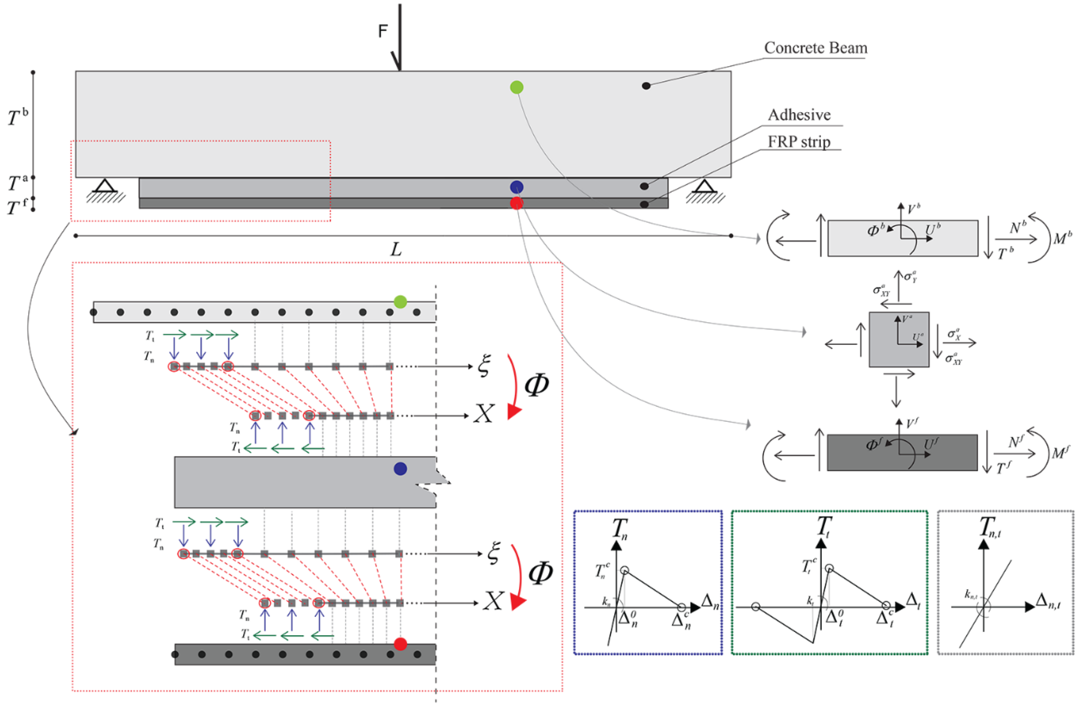
Figure 1. General representation of the numerical model.
Fibers 08 00042 g001
Figure 2. Normalised cohesive laws. Normal traction (left); shear traction and slip (right).
Fibers 08 00042 g002
Figure 3. Synoptic representation of the proposed algorithm.
Fibers 08 00042 g003
Figure 4. Fibre-reinforced polymer (FRP)-strengthened concrete beam configuration and loading scheme.
Fibers 08 00042 g004
Figure 5. Loading displacement curve: comparison with numerical data published in [18]. (a) The loading displacement curve; (b) A detail of the resistance curve at the point in which the crack onset is activated.
Fibers 08 00042 g005
Figure 6. Comparison in terms of crack tip position versus time (a); Comparison in terms of crack tip speed versus time (b).
Fibers 08 00042 g006