Abstract
In this paper, experimental investigations for strengthening reinforced concrete (RC) continuous beams were performed. Eighteen T-beams were cast, twelve of which were inverted T-beams where the flange portion of the T-beam was subjected to positive flexure to represent the support region of a continuous beam. Six of the T-beams were non-inverted where the web is subjected to positive flexure. Carbon fiber reinforced polymer sheets (CFRP) with different widths were considered, and different strengthening configurations with the same area of CFRP were investigated. The use of one-layer, multiple layers, or multiple strips of CFRP were evaluated to investigate the effect of these configurations on the ultimate capacity and ductility of the strengthened beams. From the experimental observation of the non-inverted beams, it was found that the ultimate load capacities of the CFRP-strengthened beams were enhanced by 4% to 90% compared to the control beam. Using multiple layers of CFRP sheets enhanced the stiffness of the beams by 4% to 46%, depending on the CFRP area and configurations. The debonding of CFRP before the ultimate failure provided additional ductility to the tested beams. For the strengthening of the inverted beams, it was found that the addition of CFRP strips did not increase the strength of the beams when the width of CFRP to beam width ratio was less than 0.25, but the ductility of the beam was enhanced slightly. The use of multiple strips was found to be a more effective way for the strengthening of the negative moment region than using multiple layers. This can also provide more desirable modes of failure than when applying CFRP in multiple layers. Ductility was found to be lower if multiple layers were used compared to other configurations. Moreover, it was observed that as the compressive strength of concrete increased the addition of the CFRP improved the beams ductility.
1. Introduction
Externally bonded carbon fiber reinforced polymer (CFRP) sheets are considered as an effective technique for strengthening and repairing reinforced concrete (RC) beams [1,2]. The need to strengthen concrete structures for shear or flexure may arise because of initial design or construction errors, design code updates, deterioration during service life, fires, or earthquakes. The replacement of deficient structures may be considered; however, this requires large investments. Thus, strengthening the structures for flexure and shear has become one of the favorite ways for improving the load-carrying capacity and prolonging the service life of concrete structures. Several researchers [3,4,5,6] have investigated shear strengthening by using fiber reinforced polymer (FRP) sheets, ropes and other strengthening techniques such as using FRP or mortar jacket. Some of these studies provide promising results, as it changes the mode of failure from brittle to ductile failure; it was also found that the shear capacity of the strengthened beams was increased compared to the un-strengthened beams. Other researchers have studied the flexural strengthen of the RC beams; Lamanna, et al. [7] proposed a new method for strengthening RC T-beam for flexure. They attached the FRP strips to the RC beams by using mechanical fasteners which was found to increase the moment capacity in addition to greatly increase the ductility of the strengthened beams. Chellapandian et al. [8], investigated experimentally and analytically the effectiveness of different strengthening techniques in improving the flexure behavior of RC beams. NSM, external bonding (EB) strengthening with a CFRP sheet, or hybrid strengthening, which uses a combination of NSM CFRP laminate and EB CFRP confinement, were tested. It was found that hybrid FRP strengthening significantly increases the capacity of the strengthened beams. Also, it was found that beams strengthened with hybrid FRP strengthening showed higher energy absorption capacity than other strengthened beams.
Strengthening the negative flexural region of concrete members can be more challenging than strengthening the positive region. Jumaat et al. [9] addressed some practical problems for strengthening the negative moment region of a continuous span, which is considered a critical zone due to the presence of large moment and shear at the same location. The presence of the columns at such locations prevents the application of the CFRP system over the web portion of the beam. In addition, the use of other strengthening techniques, such as thick steel plates bonded to the floor surface, will raise the floor level, which can be undesirable.
According to Akbarzadeh et al. [10], many in-situ RC beams are of continuous construction; however, little research has studied the behavior of continuous beams with external reinforcement. Ashour et al. [11] conducted an experimental study on reinforced concrete continuous beams with different arrangements of steel reinforcement and external CFRP reinforcement. The specimens were designed to fail in flexure. The modes of failure observed were laminate rupture, laminate separation, and the peeling failure of the concrete cover attached to the composite laminate.
Aiello et al. [12] studied the behavior of RC continuous beams strengthened with CFRP sheets at only negative or positive moment regions, and compared the results obtained to the RC beams strengthened at both negative and positive moment regions. Although the control beams failed by flexural, the failure of the strengthened beams occurred by the debonding of the CFRP sheets along with concrete crushing. It was found that, when the strengthening was applied to both negative and positive regions, the ultimate load capacity of the beams was high. About 20% of moment was redistributed by adding external CFRP sheets in the positive region.
Maghsoudi et al. [13] investigated the behavior and moment redistribution of reinforced high-strength concrete (RHSC) continuous beams strengthened with CFRP. The test results showed that, by increasing the number of CFRP layers, the ultimate strength increased. On the other hand, ductility, moment redistribution, and the ultimate strain of CFRP sheet decreased. In addition, it was observed that by increasing the number of CFRP sheet layers, the failure mode was change from tensile rupture to CFRP debonding. It was also concluded that limiting the end debonding was achieved by using end U-straps but did not prevent intermediate span debonding.
Akbarzadeh et al. [10] performed an experimental program to study the flexural behavior and moment redistribution of RHSC continuous beams strengthened with glass and carbon fiber reinforced polymer (GFRP and CFRP) sheets. It was shown that, by increasing the number of CFRP sheet layers, the ultimate strength increased, while ductility, moment redistribution, and CFRP strain decreased. By using GFRP sheets, it was observed that the loss in ductility and moment redistribution can be achieved with no significant increase in the ultimate strength.
Akbarzadeh et al. [14] studied the experimental behavior of six RC continuous two-span beams strengthened with externally bonded FRP sheets at the negative and positive moment regions. The beams were loaded with a concentrated load at the middle of each span. Different types of FRP (CFRP or GFRP or CFRP/GFRP) were used. The main parameters investigated were the type of FRP and the number of FRP layers. Three different failure modes were observed for the tested beams, and the test result showed that, by increasing the number of FRP sheet layers, the failure mode varied from tensile rupture to debonding of FRP sheets.
Rahman et al. [15] presented a technique for applying CFRP laminates for strengthening the negative moment region of continuous T-beams considering the constraints caused by the column. It was concluded that the proposed method of CFRP application was easy and effective. Rahman and Jumaat [16], evaluated the proposed method of the application of CFRP laminate for strengthening the tension zone of RC T-beams, and the effect of varying the length of the strengthening laminates. A total of three RC T-beams were tested, and it was found that the load-carrying capacities of the tension zone of the strengthened beams were increased by about 50% compared to un-strengthened beams. The length of the CFRP laminate recommended did not prevent the end peeling, although it increased the load capacity of the RC T-beam.
It can be concluded from the previous studies that the number, type of strengthening techniques, and the length of the CFRP layers impact the strength and ductility of the strengthened continuous beams; however, the effect of using different configurations and widths of the CFRP sheets on the response of strengthened continuous RC T-beams in the negative and positive flexural regions has not been fully investigated. Therefore, in this paper, the effect of CFRP configurations, such as the use of one-layer, multiple layers, or multiple strips, on the ultimate capacity and ductility of the strengthened beams were investigated experimentally.
2. Experimental Program
In this section, the description of the experimental programs in term of sample preparations, the material used, the bonding of the CFRP, and test procedure is provided.
2.1. Test Specimens
A total of 18 RC T-beams were fabricated for this study using 144 in (3657.6 mm) lengths with an effective span length of 108 in (2743.2 mm). The T-beam cross sectional dimensions consisted of a total depth of 10 in (254 mm), web width of 6 in (152.4 mm), flange thickness of 4 in (101.6 mm), and a flange with of 16 in (406.4 mm). Twelve of these beams were simply supported and were inverted during testing to represent the negative moment of the continuous (two-span) beams, as shown in Figure 1. The remaining six beams were not inverted to represent the positive moment region. The two regions were evaluated as such to independently collect data on the response to failure of each region. Un-strengthened control beams were also tested for each series of beams. The beam geometries and reinforcement, as well as the loading and support arrangements, are illustrated in Figure 2. The CFRP sheet configurations used are summarized in Table 1 and Table 2. The control beams (CON) have no CFRP, while the CFRP-strengthened beams are notated as nLk, where n represents the number of CFRP layers (L), and k is the layer width. For samples that were strengthened with more than one strip (ST), only one layer was used for each strip, and the notation used was mSTk, where m is the number of strips and k is the width of each strip. The casting stages of the beam specimens are shown in Figure 3. The beam specimens were cured for 3 days before removing them from their molds.
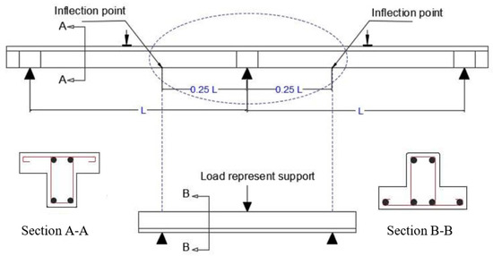
Figure 1.
Reference single span selected from two-span T-beams.
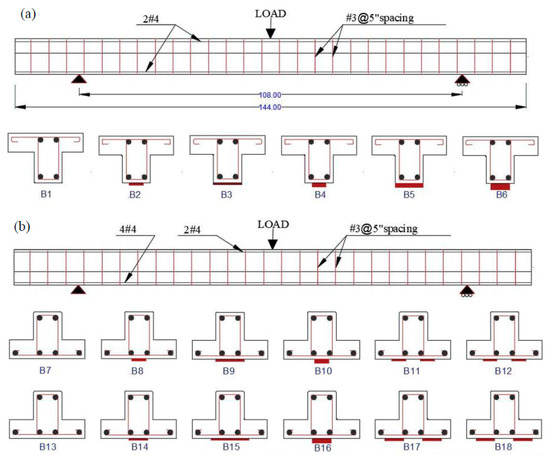
Figure 2.
Test setup showing longitudinal profile of beam, cross-section for the (a) positive and (b) negative moment region of the T-beams.

Table 1.
Test specimens’ details for the positive moment region.
Table 2.
Test specimens’ details for the inverted T-beams.
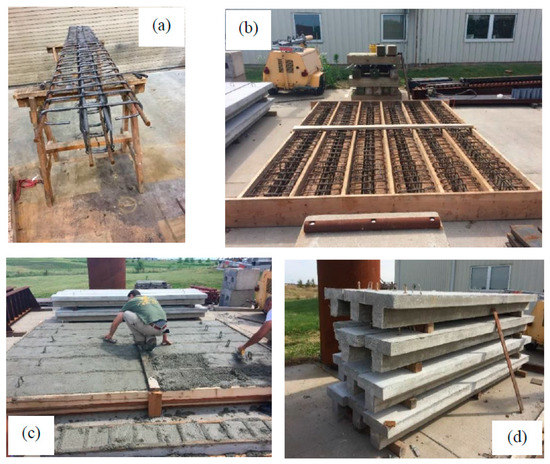
Figure 3.
Casting of the T-beams: (a) steel reinforcing cage, (b) formwork with the reinforcement cage, (c) T-beams during casting, (d) T-beams removed from their formwork.
2.2. Materials Properties
The properties of the concrete and CFRP materials used in this paper are described in this section. Specially designed ready-mixed concrete, Chat mix (Table 3), was used to fabricate the specimens. Uniaxial compressive tests of the standard concrete cylinders were performed (Figure 4). The average compressive strength was 4700 psi (31.2 MPa).
Table 3.
Chat mix concrete mixture properties.
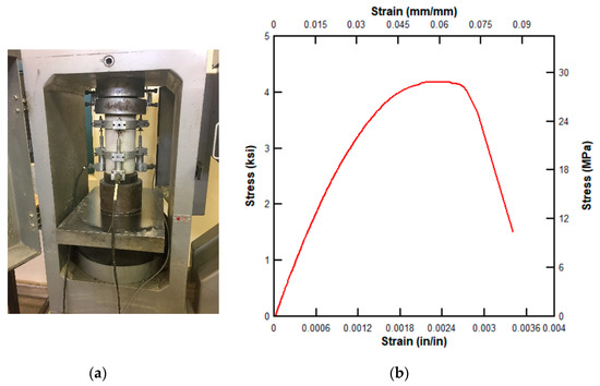
Figure 4.
Concrete cylinder compression testing: (a) test set-up, (b) typical stress–strain relationship response.
The flexural steel reinforcement of the concrete beams had a diameter of 0.5 in (12.7 mm) and a nominal yield strength of 50 ksi (345 MPa). The shear reinforcement stirrups were made from the same steel with a diameter of 0.375 in (9.5 mm). The steel reinforcement were placed in accordance with Figure 2. To prevent premature shear failure, the stirrups spacing was at 5 in (127 mm). To maintain a minimum concrete cover of 0.75 in (19 mm) for all steel, chairs were used under the reinforcing cages.
The properties of the CFRP sheets and the epoxy used were obtained from the manufacturer and are given in Table 4.
Table 4.
Manufacturer material properties of CFRP and Epoxy.
2.3. Specimens
The steel reinforcement were placed in accordance with Figure 2. To prevent premature shear failure, the stirrup spacing was at 5 in (127 mm). To maintain a minimum concrete cover of 0.75 in (19 mm) for all steel, chairs were used under the reinforcing cages. Specially designed ready-mixed concrete, Chat mix (Table 3), was used to fabricate the specimens.
2.4. Procedure for Bonding CFRP
The concrete surfaces were prepared in accordance with the manufacturer’s requirements. The concrete substrates were grinded, cleaned, and were made free of surface moisture before resin and the CFRP sheet applications. For the inverted T-beams, the lifting hooks were removed before preparing the substrates (Figure 5). After the beams’ surface preparation, a two-part epoxy was applied to the concrete surface followed by application of the CFRP sheet. The CFRP sheets were installed by starting at one end and moving along the length of the CFRP sheet until they were completely over the concrete surface. To effectively impregnate the carbon fiber sheet with the epoxy, the tool as shown in Figure 6b was used, and then a second layer of resin was applied over the CFRP sheet (see Figure 6).
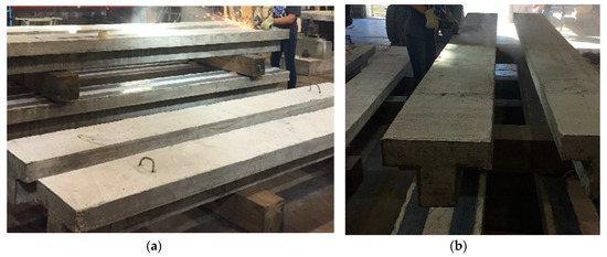
Figure 5.
Surface preparation: (a) the inverted T-beam before lifting hooks were removed; (b) concrete surface grinding.
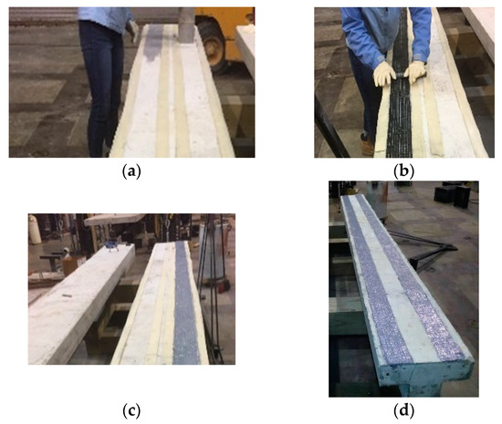
Figure 6.
The steps in T-Beam strengthening: (a) applying the first layer of epoxy; (b) adding the CFRP sheet; (c) adding the second layer of epoxy; (d) the final shape.
To avoid the debonding failure of the CFRP, the beams were strengthened with a sufficient anchorage length of the CFRP sheets of 144 in (3657.6 mm) long with different widths. For the inverted T-beams, the CFRP sheet lengths were sufficient to extend beyond the inflection points to provide the necessary anchorage.
2.5. Test Procedure
To evaluate the CFRP strengthening of the positive and negative moment regions, the T-beams were tested under three-point bending as shown in Figure 7. The negative region was tested using an inverted T-beam, with the inflection points represented by the end supports and the internal column was represented by the applied midspan loading (Figure 1, Figure 2 and Figure 7b).
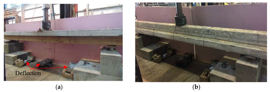
Figure 7.
Test arrangement: (a) the non-inverted T-beam for positive curvature; (b) the inverted T-beam for negative curvature.
The beams were tested under three-point bending and the displacement readings were measured at three locations. The load was applied at the midspan by a controlled hydraulic jack at a displacement rate of 0.1 in/min (2.5 mm/min). Linear variable differential transducers (LVDTs) were placed at the midspan and at quarter spans to monitor the deflection of the beam.
3. Test Results and Discussion
In this section, the experimental results obtained will be presented and discussed in terms of the observed failure mode, load-deflection response, load capacity, and ductility.
3.1. Control Beams
Three non-strengthened control beams, CON1, CON2 and CON3, were tested in this paper. Flexural failure controlled the failure mode of the control beams. Flexural cracks occurred at the midspan and extended to the compressive regions of the beams, as shown in Figure 8. Control beam CON1 failed in flexure in a ductile manner, whereas control beams CON2 and CON3 failed initially by cracking in the tension side (flange of the T-beam) in a ductile manner until the crushing of the compression concrete (web of the T-beam) occurred.
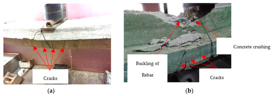
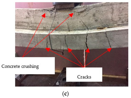
Figure 8.
Static testing of control beams showing flexural cracks and progression of failure: (a) CON1; (b); CON2; (c) CON3.
3.2. Strengthened T-Beams—Series 1
The load-deflection curves of the tested non-inverted T-beams are shown in Figure 9. These beams represent the positive moment region loading scenario. All the beams had similar steel reinforcements with different CFRP configurations. Table 5 summarizes the ultimate failure load (Pu) and the ultimate enhancement ratio (k) defined as the ratio of the ultimate load of the strengthened beam to that of the un-strengthened control beam. It can be observed that as the area of CFRP increased a significant enhancement in the load capacity was obtained. The ultimate load capacities of the CFRP-strengthened beams were enhanced by 4% to 90% compared to the control beam (beam B1). It is noticed that using the same area of CFRP in different configurations affected the response and capacity of the beams. For example, using two layers of CFRP (beam B4) enhanced the strength and corresponding deflection more than using just one layer with the same area (beam B3), as shown in Table 5 and Figure 9.
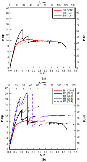
Figure 9.
Load-deflection response for series 1: (a) the effect of increasing the CFRP area; (b) the effect of increasing the number of layers with the same area of CFRP.
Table 5.
Experimental results of series 1 tested beams.
As the applied load increased towards failure, several localized drops in capacities of the CFRP-strengthened beams were recorded until complete failure (Figure 9). This could be attributed to the gradual debonding failure associated with concrete cracks. Debonding was mainly characterized by failure of the bond layer between the CFRP and the concrete. In some cases, debonding was also accompanied by the partial failure of the concrete cover. As the loading of the beams progressed, debonding occurred at different locations along the span.
It was also observed that as the CFRP area increased the mode of failure changed from CFRP rupture (beams 2, 3, and 4) to CFRP debonding (beams 5 and 6). The failure modes of the CFRP- strengthened beams are shown in Figure 10 and Figure 11. As the interfacial stresses at the boundary of the CFRP sheet increased, premature debonding failure occurred before the ultimate failure of the CFRP sheets (Figure 10). Beams 5 and 6 showed that CFRP strengthening increased the ultimate strength compared to the control beam 1 by 90% and 82%, respectively. The failure of the beams started with the initiation of cracks in the concrete, followed by localized debonding of the CFRP layers and subsequent progression of debonding of CFRP along the span length (Figure 11). The crack patterns observed in the strengthened beams after ultimate failure can be seen in Figure 12.
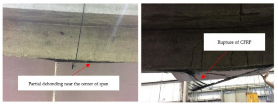
Figure 10.
Typical debonding (Left) and rupture (Right) of beams (B2–B4).
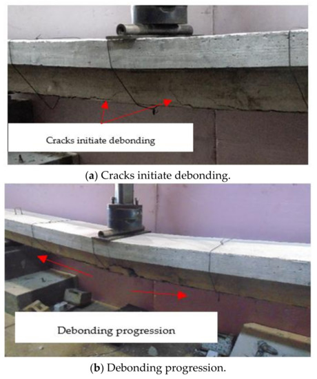
Figure 11.
Typical failure mode of beams (B5 and B6).
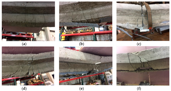
Figure 12.
Crack patterns for series 1 beams: (a) CON1-B1; (b) 1L3-B2; (c) 1L6-B3; (d) 2L3-B4; (e) 2L6-B5; and (f) 3L4-B6.
3.3. Strengthened Inverted T-Beams—Series 2
The load-deflection curves for the tested beams of series 2 are shown in Figure 13. Based on experimental observation, the load-carrying capacity of beams strengthened with a CFRP strip of 3 in (76.2 mm) width in a single layer did not enhance the ultimate capacity of the beam; however, the ductility was enhanced. However, when the strip width is increased to 6 in (152.4 mm), a 16% increase in strength was achieved. It was also observed that the strength of the beams strengthened with two layers of the same area enhanced the beam capacity by only 13% and the CFRP rupture happened earlier during the test, as seen in Figure 13. The results obtained experimentally demonstrate that applying CFRP as a single layer of a wide strip or multiple narrow strips results in better strengths than when applying CFRP in multiple layers, which is believed to be attribute to reducing the stress in the bond between the CFRP sheet and the concrete surface. The typical mode of failure for beams B8-B12 can be seen in Figure 14.
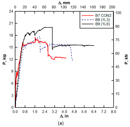
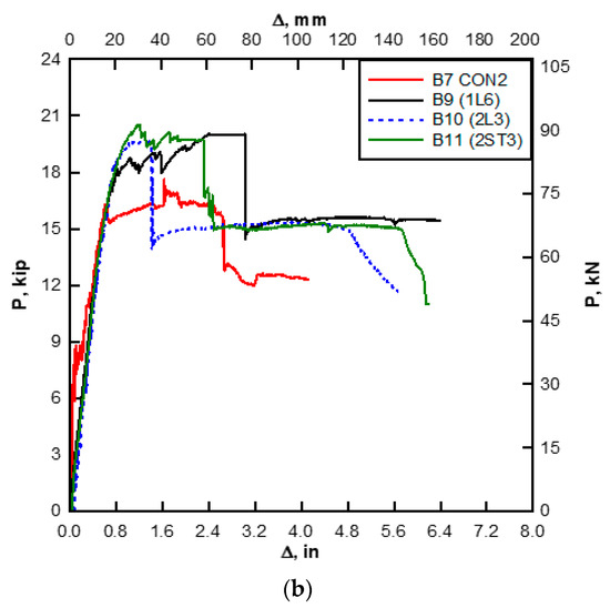
Figure 13.
Load-deflection response for series 2: (a) the effect of increasing the CFRP area; (b) the effect of configurations using the same area of CFRP.
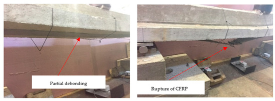
Figure 14.
Typical debonding (Left) and rupture (Right) of beams (B8–B12).
The strength enhancement of beams with two strips was very similar to that of a single strip with the same area of CFRP. In both cases, partial debonding of the CFRP was observed, but the beams failed due to a rupture of the CFRP layer. Table 6 summarizes the test results obtained for the beams of series 2. The crack patterns of the strengthened beams after the ultimate failure can be seen in Figure 15.
Table 6.
Experimental results of series 2 tested beams.
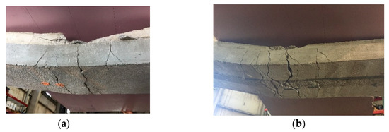
Figure 15.
Crack patterns in the concrete flange for series 2 beams: (a) CON2-B7; (b) 1L3-B8; (c) 1L6-B9; (d) 2L3-B10; and (e) 2ST3-B11. All images show crack patterns on the bottom side of the concrete flange with the CFRP removed.
3.4. Strengthened Inverted T-Beams—Series 3
The load-deflection response for the tested beams of series 3 are shown in Figure 16. The behavior of all of the beams was very similar in the early stages of loading. After that, the stiffnesses of the strengthened beams were higher than the control beam (CON3). Several localized drops in the capacities of the CFRP-strengthened beams were recorded as the applied load increased towards complete failure, as shown in Figure 16.
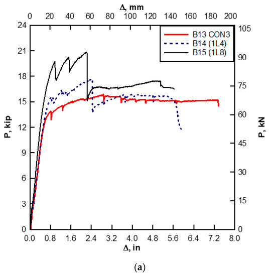
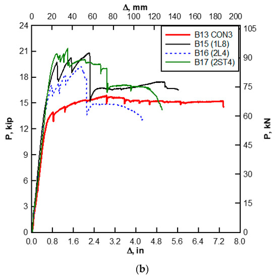
Figure 16.
Load-deflection response for series 3: (a) the effect of increasing the CFRP area; (b) the effect of configurations using the same area of CFRP.
The load-carrying capacity of beams strengthened with a 4 in (101.6 mm) width single-layer CFRP strip enhanced the ultimate capacity of the beam by about 12%. A 32% increase in strength was achieved when the single-layer strip width was increased to 8 inches (203.2 mm). It was also observed that the strength capacity of the beams strengthened with two layers having the same area (4 in (101.6 mm) for each layer) enhanced the beam capacity by only 22% as the failure mode was controlled by the debonding of the CFRP. However, using the same area of two strips made of two single layers of 4 in (101.6 mm) width each, the mode of failure changed from debonding to tensile rupture of the CFRP and a 35% increase in strength was achieved, as shown in Figure 16, Figure 17 and Figure 18.
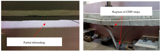
Figure 17.
Typical debonding (Left) and rupture (Right) of beams (B14, B15, and B17).
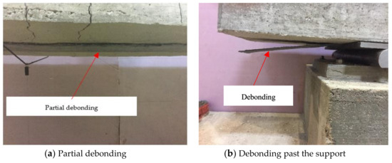
Figure 18.
Typical failure mode of beams (B16, and B18).
In Table 7, it can be seen that the addition of one and two layers of CFRP sheets of the same area increased the ultimate load capacity compared to the control beam CON3 by 32% and 22% for B15 and B16, respectively. In addition, comparing the results of B15 and B17, the enhancement was 32% compared to 35% when using two strips of the same area of CFRP.
Table 7.
Experimental results of series 3 tested beams.
It can also be observed that the ductility of the beams decreased by adding CFRP strengthening. In addition, the ductility was reduced when using multiple layers compared to when using single-layer strips of the same area of CFRP. The modes of failure and crack patterns of series 3 beams can be seen in Figure 17, Figure 18 and Figure 19. These failure modes demonstrate that applying CFRP as multiple narrow strips results in more desirable modes of failure and strengths than when applying CFRP in multiple layers.
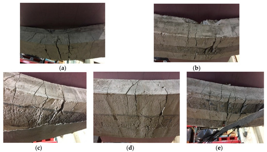
Figure 19.
Crack patterns in the concrete flange for series 3 beams: (a) CON3-B13; (b) 1L4-B14; (c) 1L8-B15; (d) 2L4-B16; and (e) 2ST4-B17. All images show crack patterns on the bottom side of the concrete flange.
4. Analytical Predictions and Test Results Comparison
In this study, ACI 440 [17] was used to predict the nominal strength of RC beams with external strengthening. The experimental results were then compared with the results obtained analytically, and it was found that the analytical prediction can safely be used to estimate the nominal strength of the strengthened beam when using different CFRP configurations with the same area, as the analytical results were found to be slightly less than the experimental results.
5. Conclusions
In this paper, the experimental investigation of strengthening RC continuous beams were presented. Eighteen T-beams were cast: 12 were inverted and six were non-inverted. Different CFRP widths were considered, and different strengthening configurations with the same area of CFRP were investigated. The use of one-layer, multiple layers, or multiple strips was evaluated to investigate the effect of these configurations on the ultimate capacity and ductility of the strengthened beams. Below is a summary of the main conclusions of this study.
For the non-inverted T-beams, the ultimate load capacities of the CFRP-strengthened beams were enhanced by 4% to 90% compared to the control beam depending on the area and configuration of the CFRP strengthening. Also, using multiple layers of CFRP sheets enhanced the strength of the beam and improved the post-ultimate response of the beam compared to beams strengthened with a single layer. In addition, using multiple layers increased the stiffness by 6% to 46%, depending on the area of the CRPF used. A slight increase in stiffness was observed when using multiple layers compared to a single layer with the same area of CFRP. Using multiple layers of CFRP enhanced the toughness of the beams by about 30% compared to the ones using a single layer of the same area of CFRP. It was also found that non-inverted CFRP-strengthened T-beams experienced multiple strength peaks and drops during testing until complete failure. This was attributed to the debonding of CFRP associated with the concrete cracks that developed during test progression. This resulted in added ductility to the tested beams before the ultimate failure was reached.
For inverted T-beams, representing negative bending of continuous beams, the load enhancement ratio ranged from 2% to 35%, depending on the area and configuration of CFRP. It was also found that, although the increase in strength when using narrow CFRP strips was small, the enhancement to ductility was more apparent. The experimental results indicated that, by applying a single layer of CFRP as a wide strip or single-layers, multiple narrow strips resulted in improved strength and a ductility performance that was better than when applying CFRP in multiple layers of the same area of CFRP. This can also provide more desirable modes of failure than when applying CFRP in multiple layers. It was observed that debonding between CFRP and concrete occurred at various stages of the testing before the ultimate failure was reached. This debonding was attributed to the flexural cracks in concrete, which provided additional ductility to the tested beams. In addition, the ultimate load and stiffness for the inverted T-beams strengthened with CFRP increased as the width-of-CFRP to the width-of-concrete ratio increased. Little enhancement in beam capacity was obtained when the CFRP width-to-concrete width ratio was less than one fourth. For these beams, it was also found that, as the compressive strength of concrete increased, the addition of the CFRP improved the beams ductility.
Comparing the experimental results with the analytical prediction, they were found to be very close. It was found that analytical prediction can safely predict the nominal strength of the strengthened beams with slight differences between them.
The results of this research show that using multiple layers of CFRP sheets enhanced the post-ultimate response of the T-beams. In addition, using multiple layers of CFRP enhanced the toughness of the non-inverted T-beams, whereas this was reduced for inverted T-beams.
6. Data Availability
Some or all data, models, or code that supports the findings of this study are deposited in a data repository and will be made available by submitting the request to the corresponding author.
Author Contributions
Investigation, A.A.-K.; Project administration, H.S.; Supervision, H.S.; Visualization, A.A.-K.; Writing—Original draft, A.A.-K.; Writing—Review & editing, A.A.-K. and H.S. All authors have read and agreed to the published version of the manuscript.
Funding
This research received no external funding.
Conflicts of Interest
The authors declare no conflict of interest.
References
- Samad, A.A.A.; Alferjani, M.B.; Ali, N.; Mohamad, N.; Ahmad, M.H.; Tee, K.F.; Mendis, P. Sustainable Shear Behaviour of 2-Span Continuous Reinforced Concrete T-Beams with CFRP Strips. Matec Web Conf. 2017, 103, 02014. [Google Scholar] [CrossRef]
- Zhang, X.; Wang, P.; Jiang, M.; Fan, H.; Zhou, J.; Li, W.; Dong, L.; Chen, H.; Jin, F. CFRP Strengthening Reinforced Concrete Arches: Strengthening Methods and Experimental Studies. Compos. Struct. 2015, 131, 852–867. [Google Scholar] [CrossRef]
- Chalioris, C.E.; Kosmidou, P.M.K.; Papadopoulos, N.A. Investigation of a New Strengthening Technique for RC Deep Beams Using Carbon FRP Ropes as Transverse Reinforcements. Fibers 2018, 6, 52. [Google Scholar] [CrossRef]
- Chalioris, C.E.; Kytinou, V.K.; Voutetaki, M.E.; Papadopoulos, N.A. Repair of Heavily Damaged RC Beams Failing in Shear Using U-Shaped Mortar Jackets. Buildings 2019, 9, 146. [Google Scholar] [CrossRef]
- Chalioris, C.E.; Zapris, A.G.; Karayannis, C.G. U-Jacketing Applications of Fiber-Reinforced Polymers in Reinforced Concrete T-Beams against Shear—Tests and Design. Fibers 2020, 8, 13. [Google Scholar] [CrossRef]
- Moradi, E.; Naderpour, H.; Kheyroddin, A. An Experimental Approach for Shear Strengthening of RC Beams Using a Proposed Technique by Embedded through-Section FRP Sheets. Compos. Struct. 2020, 238, 111988. [Google Scholar] [CrossRef]
- Lamanna, A.J.; Bank, L.C.; Borowicz, D.T. Mechanically Fastened FRP Strengthening of Large Scale RC Bridge T Beams. Adv. Struct. Eng. 2004, 7, 525–538. [Google Scholar] [CrossRef]
- Chellapandian, M.; Prakash, S.S.; Sharma, A. Experimental and Finite Element Studies on the Flexural Behavior of Reinforced Concrete Elements Strengthened with Hybrid FRP Technique. Compos. Struct. 2019, 208, 466–478. [Google Scholar] [CrossRef]
- Jumaat, M.Z.; Rahman, M.M.; Alam, M.A. Flexural strengthening of RC continuous T beam using CFRP laminate: A review. Int. J. Phys. Sci. 2010, 5, 619–625. [Google Scholar]
- Akbarzadeh, H.; Maghsoudi, A.A. Experimental and analytical investigation of reinforced high strength concrete continuous beams strengthened with fiber reinforced polymer. Mater. Des. 2010, 31, 1130–1147. [Google Scholar] [CrossRef]
- Ashour, A.F.; El-Refaie, S.A.; Garrity, S.W. Flexural Strengthening of RC Continuous Beams Using CFRP Laminates. Cem. Concr. Compos. 2004, 26, 765–775. [Google Scholar] [CrossRef]
- Aiello, M.A.; Valente, L.; Rizzo, A. Moment redistribution in continuous reinforced concrete beams strengthened with carbonfiber- reinforced polymer laminates. Mech. Compos. Mater. 2007, 43, 453–466. [Google Scholar] [CrossRef]
- Maghsoudi, A.A.; Bengar, H.A. Moment redistribution and ductility of RHSC continuous beams strengthened with CFRP. Turk. J. Eng. Env. Sci. 2009, 33, 45–59. [Google Scholar]
- Akbarzadeh, H.; Maghsoudi, A.A. Flexural Strengthening of RC Continuous Beams Using Hybrid FRP Sheets. In Advances in FRP Composites in Civil Engineering; Springer: Berlin/Heidelberg, Germany, 2011; pp. 739–743. [Google Scholar] [CrossRef]
- Rahman, M.M.; Rahman, W. Simplified method of strengthening RC continuous T beam in the hogging zone using carbon fiber reinforced polymer laminate–A numerical investigation. J. Civ. Eng. Constr. Technol. 2013, 4, 174–183. [Google Scholar]
- Rahman, M.M.; Jumaat, M.Z. The Effect of CFRP Laminate Length for Strengthening the Tension Zone of the Reinforced Concrete T-Beam. J. Sci. Res. Rep. 2013, 2, 626–640. [Google Scholar] [CrossRef]
- ACI 440.2R-17. Guide for the Design and Construction of Externally Bonded FRP Systems for Strengthening Concrete Structures; American Concrete Institute: Farmington Hills, MI, USA, 2017. [Google Scholar] [CrossRef]


© 2020 by the authors. Licensee MDPI, Basel, Switzerland. This article is an open access article distributed under the terms and conditions of the Creative Commons Attribution (CC BY) license (http://creativecommons.org/licenses/by/4.0/).