Article

Loading Dynamics of Cold Atoms into a Hollow-Core Photonic Crystal Fiber

Division of Physics and Applied Physics, School of Physical and Mathematical Sciences, Nanyang Technological University, Singapore 637371, Singapore
*
Author to whom correspondence should be addressed.
Fibers 2020, 8(5), 28; https://doi.org/10.3390/fib8050028
Submission received: 31 March 2020 / Revised: 22 April 2020 / Accepted: 23 April 2020 / Published: 1 May 2020
(This article belongs to the Special Issue Hollow-Core Photonic Crystal Fibers)

Abstract

:
Cold atoms trapped and guided in hollow-core photonic crystal fibers provide a scalable diffraction-free setting for atom–light interactions for quantum technologies. However, due to the mismatch of the depth and spatial extension of the trapping potential from free space to the fiber, the number of cold atoms in the fiber is mainly determined by the loading process from free space to waveguide confinement. Here, we provide a numerical study of the loading dynamics of cold atoms into a hollow-core photonic crystal fiber. We use the Monte Carlo method to simulate the trajectories of an ensemble of cold atoms from free space trapping potential to optical potential inside a hollow-core fiber and calculate the temperature, loading efficiency, and geometry of the ensemble. We also study the noise sources that cause heating and a loss of atoms during the process. Our result could be used to design and optimize the loading process of cold atoms into a hollow-core fiber for cold atom experiments.

1. Introduction

Recent activities, coupling cold atoms with hollow-core photonic crystal fibers (HCPCFs) [1,2], aim to scale up atom–light interactions for quantum experiments, eventually leading to compact devices. Cold atoms are one of the compelling candidates for quantum engineering because of their universality and long quantum coherence time. Conventionally, cold atoms could be trapped by optical potential [3] in free space. However, the diffraction of light limits the scalability of the trapping volume and the miniaturization of the apparatus. Hollow-core photonic crystal fibers provide an alternative solution to trap atoms via diffraction-free optical potential using light guided by the fiber. The development of low-loss HCPCFs could also facilitate the guidance of cold atoms in the fiber over a macroscopic distance, which could potentially bring new applications to the cold atom quantum technology.
Various cold atom experiments have been demonstrated with different types of photonic crystal fibers. The mechanism of loading and guiding cold atoms into the fibers through the optical potential created by the optical guided mode has been investigated experimentally. The small mode field diameters of photonic bandgap fibers are used to boost nonlinear interactions for optical switching [4]. They are also used for loading the large aspect ratios atomic ensembles in order to achieve a high optical depth of atoms for light storage experiments [5,6,7]. For Kagome lattice fibers, demonstrations of the inertia-sensitive atom interferometer [8] and long quantum spin coherence time [9] in the fiber show the potential of fiber-based cold atoms for applications in quantum sensing. Moreover, by designing multiple low-loss transmission bands in the fiber, Rydberg atoms are excited by 780 nm and 480 nm light, which are simultaneously guided through the fiber [10]. On the fundamental physics side, the collective emission of light from an atomic ensemble has also been observed and studied in the fibers [11,12], and could potentially be used to study the long-range interactions of neutral atoms. Despite the above experimental progress and a preliminary study of atom loading [13,14,15,16,17], a detailed understanding of the dynamics under different loading parameters would facilitate the design of cold atom experiments in the fibers. Here, we simulate the loading process of cold atoms into a fiber with different loading parameters and calculate the distribution, efficiency, and temperature of atoms inside the fiber.

2. Materials and Methods

The parameters in the simulation are based on the experiment in [8]. A cold 85Rb atomic ensemble is prepared from the background atomic vapor by Doppler and sub-Doppler laser cooling in a three-dimensional magneto-optical trap (MOT) [18]. After the cooling process, there are ~108 atoms in the trap. The atomic cloud is trapped a few millimeters above a piece of 4-cm-long hollow-core photonic crystal fiber. The configuration of the experiment is shown in Figure 1. The fiber has a mode field radius of 22 μm. Atoms in the trap are considered under thermal equilibrium and follow a Maxwell–Boltzmann distribution. The probability density function has the form:
  f ( v ) =   ( m 2 π k B T ) 3 / 2 e - mv 2 2 k B T ,
where m is the mass of 85Rb, kB is the Boltzmann constant, v is the velocity of atoms, and T is the temperature.
The number density of atoms in the MOT is assumed to be in the low-density range, which follows the Gaussian distribution. Our simulation starts by switching off the MOT and switching on the optical dipole beam. The optical dipole beam, with a wavelength of λ = 821 nm, is coupled from the bottom of the fiber, and the profile of the optical dipole beam exiting the top facet is assumed to be a Gaussian distribution whose beam waist is located at the fiber tip. The intensity profile of the optical dipole beam can be expressed as:
I ( r , z ) = I 0 ( w 0 w ( z ) ) 2 exp ( - 2 r 2 w ( z ) 2 ) ,
where I0 is the intensity at the center of the beam, w0 is the beam waist, w(z) = w0(1 + (z/zR)2)1/2 is the radius of the beam along the propagation direction, and zR = πw02/λ is the Rayleigh range. The optical dipole beam causes a position-dependent energy shift (AC Stark shift) of atoms, which results in a dipole force that attracts atoms into the high-intensity region when the wavelength of the optical dipole beam is longer than the atomic transition wavelength (795 nm). The trapping potential U can be written as [3]:
  U ( r ) = 3 π c 2 2 ω 0 3 Γ Δ I ( r ) ,
where c is the speed of light in a vacuum, ω0 is the optical dipole beam frequency, Γ is the excited state decay rate of atoms, and Δ is the frequency detuning of the optical dipole beam below the atomic resonance. The potential U is defined in terms of temperature U = kBT in this article.
We use Monte Carlo simulation to study the trajectories of an ensemble of atoms. Atoms are randomly selected from the MOT and subjected to the dipole force, scattering force, and gravity. The dipole force attracts atoms into the fiber and causes atoms to oscillate in the radial direction. The scattering force is due to the absorption and the scattering in the random direction of the dipole beam by atoms. The trajectories of atoms are firstly obtained by solving the differential equation:
d 2 r d t 2 = - U ( r ) m + g ,
where rx + y + z, and g is the gravitational acceleration.
We solve the equation numerically, and the position and velocity of atoms in the x, y, and z-axis can be obtained as:
r i + 1 = r i + v i Δ t + a i Δ t 2 2 v i + 1 = v i + a i + a i + 1 2 Δ t ,
where vi is the velocity, and ai is the acceleration at the time step i. The time resolution Δ t of our simulation is chosen to be 2 × 10⁻⁵ s, which is smaller than the time between scattering events of 0.14 s and the oscillation period ~10−4 s of atoms in the radial direction.
For the scattering force, atoms gain a speed change of ħk/m in the z-axis from every absorption and another speed change ħkD1/m by spontaneously emitting a photon into random directions, where k is the wavenumber of the optical dipole beam and kD1 = 2π/795 nm−1 is the wavenumber of the Rb D1 line. The velocity change due to random scattering in our simulation is assigned as:
Δ v = ħ k m z + ħ k D 1 m ζ ,
where ζ is a unit vector pointing to a random direction.
If atoms collide with the fiber wall, we assume they are thermalized to the room temperature and escape the 4-cm long fiber through the axial direction. Atoms undergoing this process are considered lost during the loading process. The number of atoms in MOT is set to be 1 million. The origin of the coordinate system is located at the center of the fiber tip, as shown in Figure 1. We neglect atom–atom collisions in our simulations. The overall simulation time for one set of parameter runs is 37.5 h using 32 cores, 2.6 GHz CPU.
In our simulation, we also consider the effect of the first higher-order mode of the fiber for the loading process. In a circular symmetrical optical waveguide, linearly polarized (LP) modes are radially symmetric. In the simulation, for simplicity, we only consider the two lowest order LP modes (LP01 and LP11) because high-order modes in the optical fiber decay much faster than lower-order modes [19]. Here, we set the polarization of the fundamental mode along the y-axis. The electric field of the LP01 mode can then be expressed as:
E y =   J 0 ( k 0 x 2 + y 2 ) e i ( β 0 z - ω 0 t ) y ,
where J0 is the Bessel function of the first kind, k0 determines the size of the LP01 mode, β0 is the propagation constant, and y is the unit vector pointing in the positive y-direction. k0 and β0 are determined by the geometry of the design and the material of the fiber.
The LP11 mode is the linear combination of four basic modes, the electric field of which can be expressed as [20]:
e xo = J 1 ( k 1 x ) cos ( θ ) e i ( β 1 z - ω 0 t ) x e yo = J 1 ( k 1 y )   sin ( θ )   e i ( β 1 z - ω 0 t ) y e xe = J 1 ( k 1 x ) sin ( θ ) e i ( β 1 z - ω 0 t ) x e ye = J 1 ( k 1 y ) cos ( θ ) e i ( β 1 z - ω 0 t ) y ,
The subscripts o and e represent odd and even symmetry, respectively, and θ is the angular coordinate. J1 is the Bessel function of the first kind, k1 determines the size of the LP11 mode and β1 is the propagation constant. In our simulation, we consider two cases. One is with just the fundamental mode in the fiber, and the other one is with both the fundamental mode and the eyo component of the LP11 mode in the fiber.

3. Results and Discussion

3.1. LP01 Mode of the Optical Dipole Beam

The atom loading efficiency is defined by the ratio of the maximum number of atoms in the fiber and the total number of atoms in the MOT. We first study three parameters, including the atom temperature in the MOT, the depth of the dipole potential, and the position of the MOT in the xy plane. A list of simulation parameters is shown in Table 1.
We only vary one parameter in Table 1 for each simulation of atom loading. The results of the atom loading simulation are shown in Table 2. When we reduce the MOT temperature from 10 μK to 1 μK, the atom loading efficiency doubles. This can be explained by the increase in the number of atoms in the phase space volume. When the dipole beam power is lower, fewer atoms are loaded as the capture volume in phase space is smaller. In the atom loading experiment, it is hard to position the MOT right above the hollow-core fiber tip, so we give the MOT position a small lateral offset. The result shows that the loading efficiency is not sensitive to the position shift of 10%.
Figure 2a shows the atom distribution along the x-axis with the reference parameters. Atoms nearly follow a Gaussian distribution, which can be explained by the Gaussian profile of the dipole beam inside the fiber. The mean and standard deviation of atoms’ positions are found to be 0.06 μm and 11.14 μm, respectively, by fitting a Gaussian function. Because of the symmetry of fundamental mode, the atoms’ distribution along the y-axis shows similar results, with a mean of 0.04 μm and a standard deviation of 11.21 μm. The atoms’ velocity distribution along the x-axis is shown in Figure 2b, which also follows a Gaussian distribution. The standard deviation σ is used to calculate the temperature as T2m/kB, and the result is 72 μK. For the experiment in [8], the temperature was measured as 100 μK using the release-and-probe method.
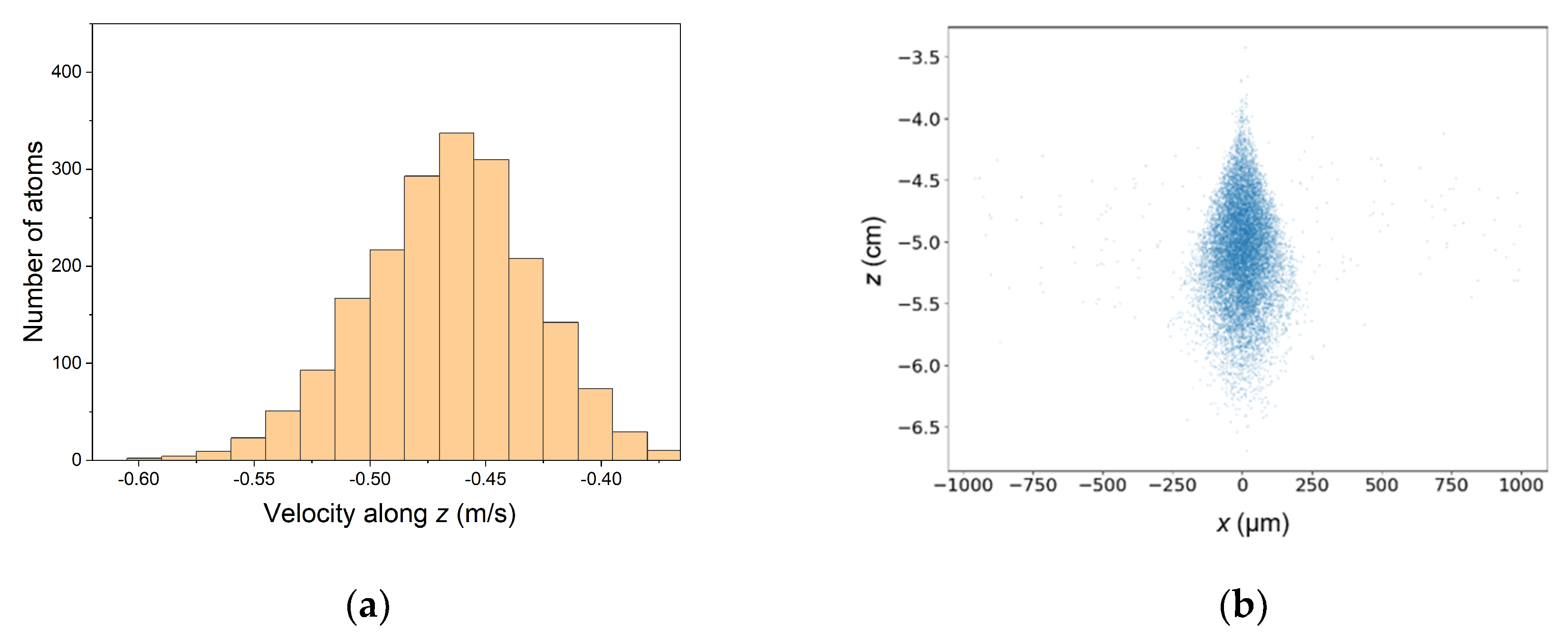
The atoms’ velocity distribution along the z-axis is shown in Figure 3a. The distribution does not follow a Gaussian distribution well. This is due to the convergence of the dipole beam into the fiber that attracts atoms along the z-axis. The atoms’ distribution in the xz plane after exiting the bottom facet of the fiber is shown in Figure 3b. This corresponds to 105 ms after release from the MOT. After atoms exit the fiber, the atomic cloud expands quickly, in a similar manner to the diverging profile of the dipole beam.

3.2. Superposition of LP01 and LP11 Modes of the Optical Dipole Beam

Due to the imperfect coupling of the optical dipole beam into the hollow-core fiber, there is a non-negligible amount of excitation in the higher-order modes. The fundamental mode and the high-order mode tend to have different indexes of refraction in the hollow-core fiber, resulting in intensity modulation on the guided light. For atoms traveling in an optical dipole potential, this intensity modulation will cause the heating of the atoms, which leads to the loss of atoms in the trap. We study this effect on the loading of atoms by introducing the superposition of the LP01 and LP11 modes, as shown in Figure 4. The power ratio of the LP01 and LP11 mode is set to 9:1 in the simulation. The beating period of two modes is determined by propagation constants in Equations (7) and (8). Here the difference of the effective refractive index is 15 × 10−4. It is clear that the minimum potential is wiggling along the z-axis.
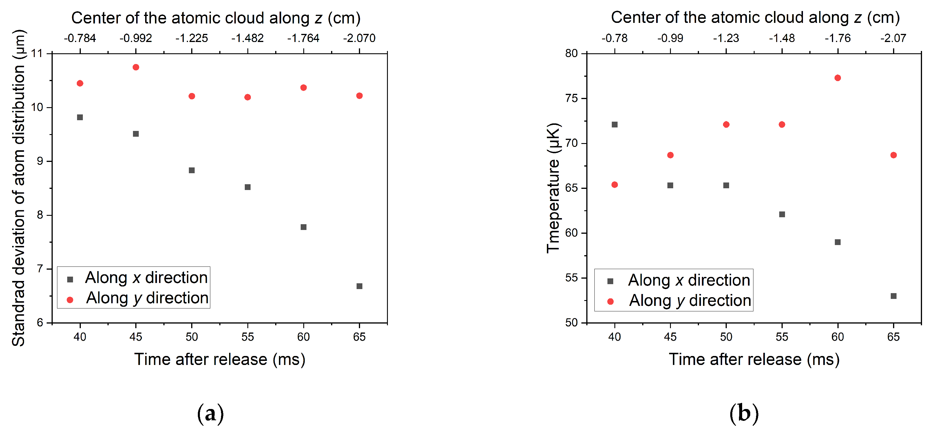
The simulation of the atoms’ distribution along the x and y axes with time is shown in Figure 5a. The plot starts 40 ms after the time of release, because it is the time when nearly all atoms enter the fiber. At each time, we use a Gaussian function to fit the histogram of the atoms’ spatial distribution in order to obtain the standard deviation. The standard deviation along the y-axis is around 10.5 μm. However, the standard deviation along the x-axis decreases from 10 μm to 6.5 μm, which means that the atomic cloud shrinks asymmetrically in the fiber. The shrink could be due to the temperature decrease in the atoms. The 1/e radius of the atomic cloud size in an optical dipole trap can be determined by the temperature of the atoms, the size of the trap, and the potential of the trap as (w2kBT/2U)1/2.
The temperature of atoms in different directions is calculated from the velocity distribution and is shown in Figure 5b. The temperature along with the y-axis increases as expected from the intensity modulation along the y-axis. The decrease in the temperature along the x-axis is due to the coupling between the x and y axes.
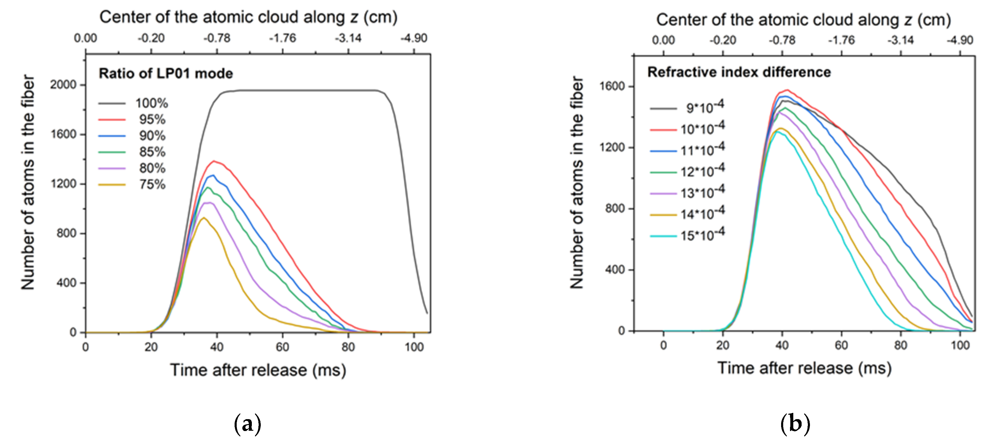
Figure 6a shows the number of atoms in the fiber versus the loading time with the different energy ratios of the LP01 and LP11 modes. With the LP01 mode at 100%, all atoms enter the fiber after 40 ms, and the number of atoms from 45 ms to 95 ms remains constant, which means all of them stay in the dipole trap. After 95 ms, atoms start to exit the fiber. If the LP11 mode and the LP01 mode mix together, the interference pattern in the fiber causes a heating effect. The atom loading efficiency decreases with the decrease in the ratio of the LP01 mode, which is similar to the experimental data shown in [8].
We also study the effect of the difference of the refractive index between the LP01 mode and the LP11 mode on atom loading, as shown in Figure 6b. With a difference in the effective refractive index of 9 × 10⁻⁴, two decay trends can be found. The first decay trend is caused by the heating effect. The second one is caused by the fact that atoms have exited the fiber. As the difference in the effective refractive index increases, atoms are heated more rapidly due to the shorter period of modulation (see Figure 4). With a larger difference in the effective refractive index, the curve shows a steeper slope.

4. Conclusions

We numerically simulated the loading dynamics of cold atoms into a hollow-core fiber and studied their efficiency with different parameters. Our results show that the heating due to the intensity modulation from the higher-order modes is the main loss mechanism. To avoid this effect, one can use a longer fiber to filter out the higher-order modes, as they tend to decay faster than the fundamental modes. One could couple the optical dipole beam at one end and load atoms at the other end. In addition, a smaller fiber core can be used to minimize the higher-order modes as well. An active way to avoid the heating loss is to cool the atoms while they are inside the fiber. This can be implemented with Doppler or sideband cooling [21]. With an improvement in loading efficiency and the minimization of heating loss, one could envision guiding a quantum particle over a long distance, in a similar manner to the way in which light is guided through the optical fibers, making this method effective for quantum engineering applications.

Author Contributions

Conceptualization, Y.W., S.C., M.X., W.S.L., Z.C., and S.-Y.L.; methodology, Y.W., S.C., M.X., W.S.L., Z.C., and S.-Y.L.; software, Y.W.; validation, Y.W., S.C., M.X., W.S.L., Z.C., and S.-Y.L.; formal analysis, Y.W., S.C., M.X., W.S.L., Z.C., and S.-Y.L.; investigation, Y.W., S.C., M.X., W.S.L., Z.C., and S.-Y.L.; writing—Original draft preparation, Y.W., S.C., M.X., W.S.L., Z.C., and S.-Y.L.; writing—Review and editing, Y.W., S.C., M.X., W.S.L., Z.C., and S.-Y.L.; supervision, S.-Y.L.; funding acquisition, S.-Y.L. All authors have read and agreed to the published version of the manuscript.

Funding

This research was funded by Singapore National Research Foundation under Grant No. NRFF2013-12, Quantum Engineering Programme under Grant No. QEP-P4, and Singapore Ministry of Education under Grant No. MOE2017-T2-2-066.

Conflicts of Interest

The authors declare no conflict of interest.

References

  1. Markos, C.; Travers, J.C.; Abdolvand, A.; Eggleton, B.J.; Bang, O. Hybrid photonic-crystal fiber. Rev. Mod. Phys. 2017, 89, 045003. [Google Scholar] [CrossRef] [Green Version]
  2. Debord, B.; Amrani, F.; Vincetti, L.; Gérôme, F.; Benabid, F. Hollow-core fiber technology: The rising of gas photonics. Fibers 2019, 7, 16. [Google Scholar] [CrossRef] [Green Version]
  3. Grimm, R.; Weidemüller, M.; Ovchinnikov, Y.B. Optical dipole traps for neutral atoms. Adv. At. Mol. Opt. Phys. 2000, 42, 95–170. [Google Scholar]
  4. Bajcsy, M.; Hofferberth, S.; Balic, V.; Peyronel, T.; Hafezi, M.; Zibrov, A.S.; Vuletić, V.; Lukin, M.D. Efficient all optical switching using slow light within a hollow fiber. Phys. Rev. Lett. 2009, 102, 203902. [Google Scholar] [CrossRef] [PubMed]
  5. Blatt, F.; Halfmann, T.; Peters, T. One-dimensional ultracold medium of extreme optical depth. Opt. Lett. 2014, 39, 446. [Google Scholar] [CrossRef] [PubMed] [Green Version]
  6. Blatt, F.; Simeonov, L.S.; Halfmann, T.; Peters, T. Stationary light pulses and narrowband light storage in a laser-cooled ensemble loaded into a hollow-core fiber. Phys. Rev. A 2016, 94, 043833. [Google Scholar] [CrossRef] [Green Version]
  7. Peters, T.; Wang, T.-P.; Neumann, A.; Simeonov, L.S.; Halfmann, T. Single-photon-level narrowband memory in a hollow-core photonic bandgap fiber. Optics Express 2020, 28, 5340–5354. [Google Scholar] [CrossRef] [PubMed]
  8. Xin, M.; Leong, W.S.; Chen, Z.; Lan, S.-Y. An atom interferometer inside a hollow-core photonic crystal fiber. Sci. Adv. 2018, 4, e1701723. [Google Scholar] [CrossRef] [PubMed] [Green Version]
  9. Xin, M.; Leong, W.S.; Chen, Z.; Lan, S.-Y. Transporting long-lived quantum spin coherence in a photonic crystal fiber. Phys. Rev. Lett. 2019, 122, 163901. [Google Scholar] [CrossRef] [PubMed] [Green Version]
  10. Langbecker, M.; Noaman, M.; Kjærgaard, N.; Benabid, F.; Windpassinger, P. Rydberg excitation of cold atoms inside a hollow core fiber. Phys. Rev. A 2017, 96, 041402(R). [Google Scholar] [CrossRef] [Green Version]
  11. Yoon, T.; Ding, Z.; Flannery, J.; Rajabi, F.; Bajcsy, M. Monitoring Raman emission through state population in cold atoms confined inside a hollow-core fiber. Optics Express 2019, 27, 17592–17600. [Google Scholar] [CrossRef] [PubMed]
  12. Okaba, S.; Yu, D.; Vincetti, L.; Benabid, F.; Katori, H. Superradiance from lattice-confined atoms inside hollow core fiber. Commun. Phys. 2019, 2, 136. [Google Scholar] [CrossRef] [Green Version]
  13. Hilton, A.P.; Perrella, C.; Benabid, F.; Sparkes, B.M.; Luiten, A.N.; Light, P.S. High-efficiency cold-atom transport into a waveguide trap. Phys. Rev. Appl. 2018, 10, 044034. [Google Scholar] [CrossRef] [Green Version]
  14. Okaba, S.; Takano, T.; Benabid, F.; Bradley, T.; Vincetti, L.; Maizelis, Z.; Yampol’skii, V.; Nori, F.; Katori, H. Lamb-Dicke spectroscopy of atoms in a hollow-core photonic crystal fiber. Nat. Commun. 2014, 5, 4096. [Google Scholar] [CrossRef] [Green Version]
  15. Vorrath, S.; Möller, S.A.; Windpassinger, P.; Bongs, K.; Sengstock, K. Efficient guiding of cold atoms through a photonic band gap fiber. New J. Phys. 2010, 12, 123015. [Google Scholar] [CrossRef]
  16. Bajcsy, M.; Hofferberth, S.; Peyronel, T.; Balic, V.; Liang, Q.; Zibrov, A.S.; Vuletić, V.; Lukin, M.D. Laser-cooled atoms inside a hollow-core photonic-crystal fiber. Phys. Rev. A 2011, 83, 63830. [Google Scholar] [CrossRef] [Green Version]
  17. Christensen, C.A.; Will, S.; Saba, M.; Jo, G.B.; Shin, Y.I.; Ketterle, W.; Pritchard, D. Trapping of ultracold atoms in a hollow-core photonic crystal fiber. Phys. Rev. A 2008, 78, 033429. [Google Scholar] [CrossRef] [Green Version]
  18. Metcalf, H.; van der Straten, P. Laser Cooling and Trapping; Springer: Berlin/Heidelberg, Germany, 1999. [Google Scholar]
  19. Bradley, T.D.; Wheeler, N.V.; Jasion, G.T.; Gray, D.; Hayes, J.; Gouveia, M.A.; Sandoghchi, S.R.; Chen, Y.; Poletti, F.; Richardson, D.; et al. Modal content in hypocycloid Kagomé hollow core photonic crystal fibers. Optics Express 2016, 24, 15798–15812. [Google Scholar] [CrossRef] [PubMed]
  20. Snyder, A.W.; Young, W.R. Modes of optical waveguides. JOSA 1978, 68, 297–309. [Google Scholar] [CrossRef]
  21. Huang, C.; Kuan, P.-C.; Lan, S.-Y. Laser cooling of 85Rb atoms to the recoil-temperature limit. Phys. Rev. A 2018, 97, 023403. [Google Scholar] [CrossRef] [Green Version]
Figure 1. Configuration of the model for the simulation. The magneto-optical trap (MOT) has a radius of 2 mm, and the atomic cloud expands when released from the MOT.
Fibers 08 00028 g001
Figure 2. (a) Histogram of atom distribution in the x-axis. The curve is a Gaussian fit to the histogram. The mean and standard deviation of atom position are found to be 0.06 μm and 11.14 μm, respectively. (b) Histogram of velocity distribution along the x-axis. The curve is a Gaussian fit to the histogram. The mean and standard deviation of atom velocities are found to be −0.0029 m/s and 0.0840 m/s, respectively. The standard temperature is calculated to be 72 μK.
Fibers 08 00028 g002
Figure 3. (a) Histogram of atoms’ velocity distribution in z-axis 45 ms after release. (b) The atoms’ distribution in the xz plane after exiting the fiber. The bottom facet of the fiber is at a position of (0, 0, −4) cm.
Fibers 08 00028 g003
Figure 4. Intensity distribution in the fiber with a superposition of linearly polarized (LP)01 and LP11 modes. The power ratio of the LP01 and LP11 mode is set to be 9:1. (a) Intensity distribution on the yz plane. The interference of the two modes gives an intensity modulation with a period of difference in the wavenumbers on the z-axis. The origin of the coordinate is set at the upper tip of the fiber; (b) and (c) are the intensity distribution in the fiber cross-section at different z positions. The position of the peak intensity shifts along the z-axis.
Fibers 08 00028 g004
Figure 5. (a) The standard deviation of atom distribution versus time. (b) The temperature of the atoms in the x and y directions versus time.
Fibers 08 00028 g005
Figure 6. (a) Number of atoms in fiber versus time with different energy ratio of LP01 mode. (b) The number of atoms in the fiber versus time with different effective refractive index differences.
Fibers 08 00028 g006
Table 1. A list of the reference parameters for the simulation and comparison with other works.
ParametersOur WorkReference [13]Reference [16]
MOT temperature10 μK5 μK40 μK
MOT center position(0,0,5) mm(0,0,25) mm(0,0,6) mm
MOT 1/e2 radius2 mm1 mmN.A.
Dipole beam power0.5 W (313 μK trap depth)1 W (14 mK trap depth)25 mW (10 mK trap depth)
Dipole beam wavelength821 nm797.25 nm802 nm
Length of the fiber4 cm10 cm3 cm
Core diameter64 μm45 μm7 μm
Efficiency0.19% (simulation)3.2% (experiment)3% (experiment)
Table 2. Atom loading efficiency with different parameters. The first row refers to the parameters from Table 1, and the other rows differ from the first row by the parameter indicated.
ParametersLoading Efficiency
Reference parameters0.19%
MOT temperature: 1 μK0.39%
Dipole beam power: 0.17 mW (106 μK trap depth)0.1%
MOT position: (0.28, 0, 5) mm0.17%
MOT position: (0.42, 0, 5) mm0.18%