Article

Transmission of Orbital Angular Momentum and Cylindrical Vector Beams in a Large-Bandwidth Annular Core Photonic Crystal Fiber

1
Department of Electrical Engineering, École de Technologie Supérieure, Montréal, QC H3C 1K3, Canada
2
Center for Optics, Photonics and Lasers, Université Laval, Quebec, QC G1V 0A6, Canada
*
Author to whom correspondence should be addressed.
Fibers 2020, 8(4), 22; https://doi.org/10.3390/fib8040022
Submission received: 10 March 2020 / Revised: 31 March 2020 / Accepted: 2 April 2020 / Published: 4 April 2020

Abstract

:
The stable propagation of orbital angular momentum and cylindrical vector beams in a newly designed annular core photonic crystal fiber (AC-PCF) tailored for the broadband single-radial order beam transmission (within the so-called “endlessly mono-radial” guiding regime) is demonstrated for the first time. It is shown that the vector-vortex beams can maintain high mode purities above 18 dB after propagation in the fiber under test over all of the wavelength range from 805 to 845 nm (over 17 THz bandwidth) investigated with the help of a tunable laser and an S-plate for the generation of singular beams in free space. Our results confirm that the AC-PCF is a promising design for the broadband transmission of vector-vortex beams that have potential applications in space-division multiplexing, quantum communications, optical sensing and trapping.

1. Introduction

We are still in the early stages of grasping the fundamental implications and applications of the vector-vortex beams. The so-called vortex beams carrying orbital angular momentum (OAM) harbor a phase singularity, while the cylindrical vector beams (CVB) present polarization singularities in their beam profiles [1,2,3]. Conspicuously, both types of optical singularities lead to a beam recognized by a doughnut-shaped intensity profile. OAM beams can carry both spin and orbital angular momentum due to discrete states in circular polarization and helical phase (written as exp(iLθ) where L is the topological charge and θ the azimuthal angle), respectively. Vortex beams have demonstrated promising advances in optical microscopy, optical trapping, space-division multiplexing, optical communications and for probing new (non)linear chiral light-matter interactions [3,4,5,6,7,8,9,10]. Similarly, some CVBs (especially the radial TM01 and azimuthal TE01 polarized beams) exhibit unique properties that enable novel light-matter interactions that can be exploited in super-resolution imaging, laser material processing and optical trapping, among others [1,11,12,13,14].
There is vigorous research being conducted to push the field further using both bulk optics and fiber-optic based platforms. Prior studies have demonstrated that fiber designs with a high-index annular core (i.e., “ring-core”) represent one of the most efficient approaches for the coupling and propagation of vector-vortex beams owing to the strong overlap between the beam’s optical intensity profile and the refractive index profile of the fibers [15,16,17,18]. Moreover, it was determined early on that suitable fiber designs must lift the modal degeneracy between the fiber eigenmodes in order to promote modal stability of CVB and OAM guided beams through lower crosstalk. The common rule to enable such stable transmission is to maintain intermodal refractive index separation of Δneff ≥ 10−4 between adjacent vector modes [19,20]. Solid annular-core fibers have shown interesting results [16,18,19] but have limitations in terms of achievable intermodal separations, chromatic dispersion and mode selection.
Microstructured fibers and photonic crystal fibers (PCF) in particular have recently attracted significant research interest towards alleviating the above limitations of solid-core fibers by exploiting the significantly increased design freedom afforded by the holey structure and the unique modal properties that emerge [21,22,23,24,25,26]. A particular design of annular-core photonic crystal fiber (AC-PCF) recently proposed the theoretical ability to enforce mono-radial vector-vortex mode guiding while preventing higher-radial order modes over a very large bandwidth [27]. This unique waveguiding regime termed “endlessly mono-radial” (EMR) occurs when the periodic photonic crystal cladding has holes with a diameter (d) to pitch (Λ) ratio below a certain threshold: d/Λ < 0.35. Recently, Tandjè et al. demonstrated vortex beam propagation inside a ring core photonic crystal fiber, although the latter fiber design was not EMR and the experimentally achieved OAM mode purities remained limited [28].
In this work, the first experimental demonstration of both CVB and OAM beam transmission inside an endlessly mono-radial AC-PCF was performed. The stability of vector-vortex mode guiding in the AC-PCF was confirmed through polarimetric and interferometric measurements, which indicated good mode purity (>18 dB) over the whole 40 nm (17 THz) bandwidth investigated with a near-infrared tunable laser.

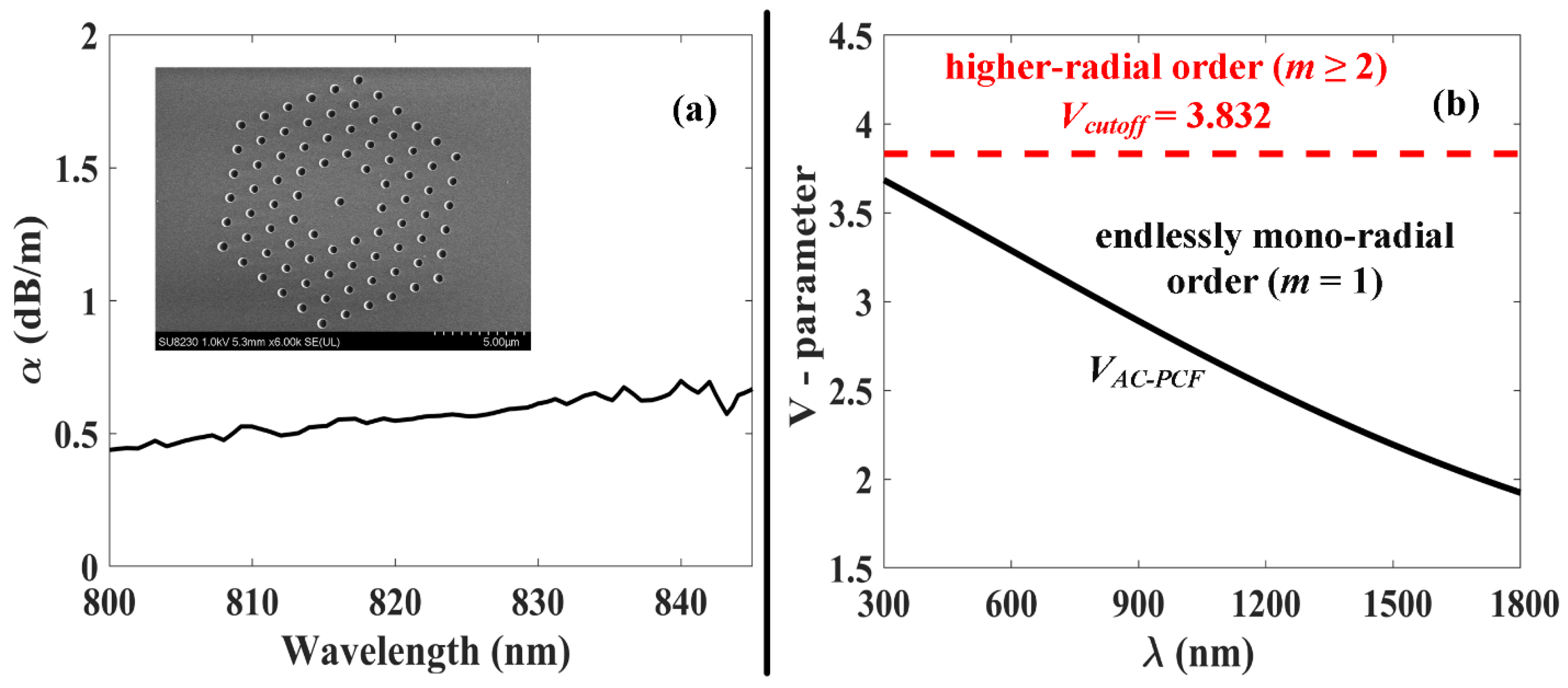
2. Mode structure and Attenuation in AC-PCF

The fabricated AC-PCF used in this work has a microstructure defined by air holes of average diameter (d = 0.48 μm) and separated by a periodic spacing of Λ = 1.4 μm (scanning electron microscope (SEM) image of the cross-section is shown in Figure 1a), thus fulfilling the condition for operation in the “EMR” waveguiding regime (d/Λ < 0.35), where waveguiding is restricted to the following mono-radial modes: HE11, TE01, HE21, TM01, HE31 and EH11. The effective core radius is given by a = 2 Λ 3 = 1.62 μm, as defined in [27]. The attenuation losses for the fundamental mode were measured in the wavelength range from 800 to 845 nm via the cutback method. The results in Figure 1a indicate average optical losses of around 0.5 dB/m inside the wavelength range of interest.
To ensure the mono-radial operation of the few-mode fiber, it is critical to prevent excitation of the first bi-annular eigenmode (HE12) of fiber, which occurs for VVcutoff = 3.832. Here, the V-parameter for the AC-PCF is defined as [27]:
V = 2 π a λ ( n core 2 n FSM 2 )
where a is the effective core radius, ncore is the refractive index of the solid glass material of the fiber (in this instance fused silica) and nFSM denotes the effective refractive index of the so-called fundamental space-filling mode (nFSM) in a triangular lattice of air-holes [29]. Based on the specific geometry of our AC-PCF, full-vector finite-element method simulations of the V-parameter were performed [see Figure 1b], which confirmed that the fiber remains mono-radial (V < Vcutoff) irrespective of the input wavelength of excitation (i.e., operates in the EMR regime). We note that the simulations were only limited in practice on the UV end at 300 nm by the transmission window of the material, and not by a limitation of the EMR regime, which in theory applies for the whole electromagnetic spectrum.

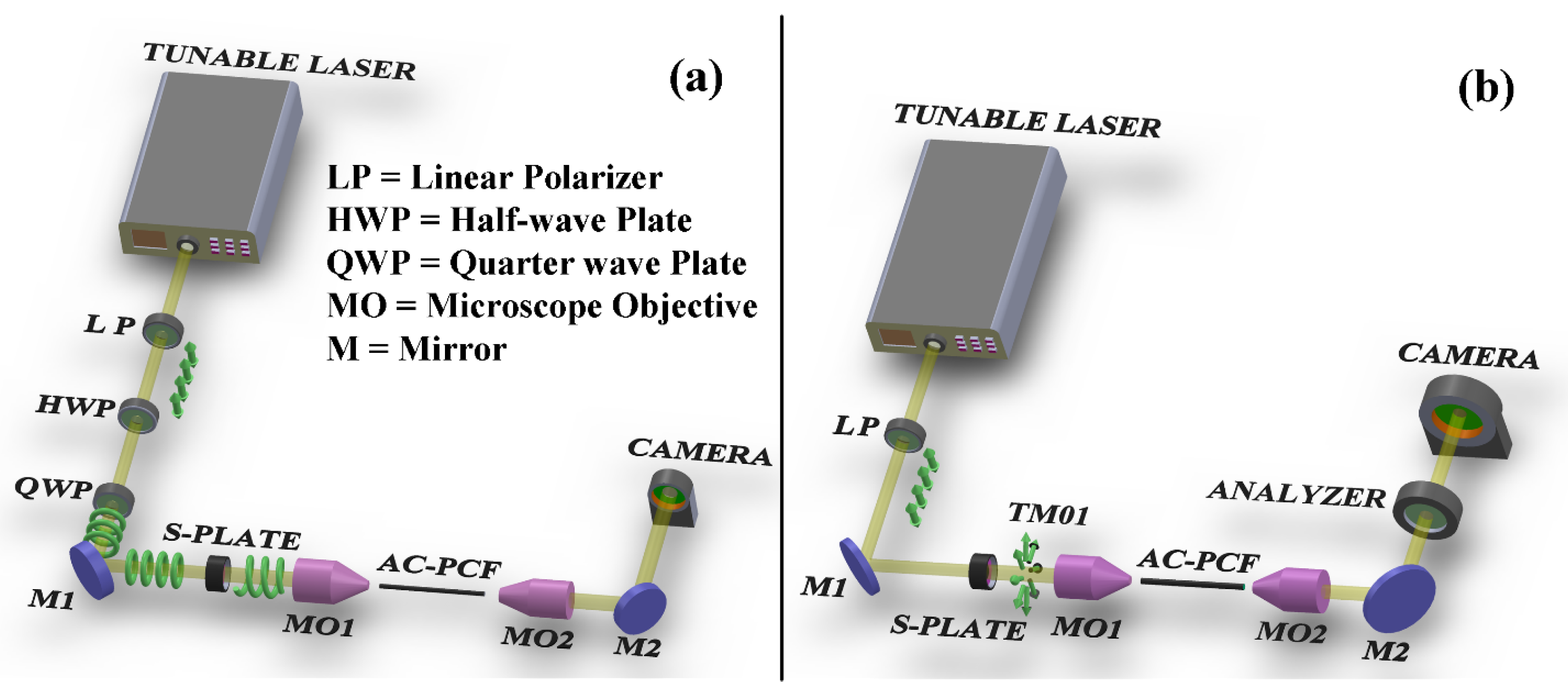
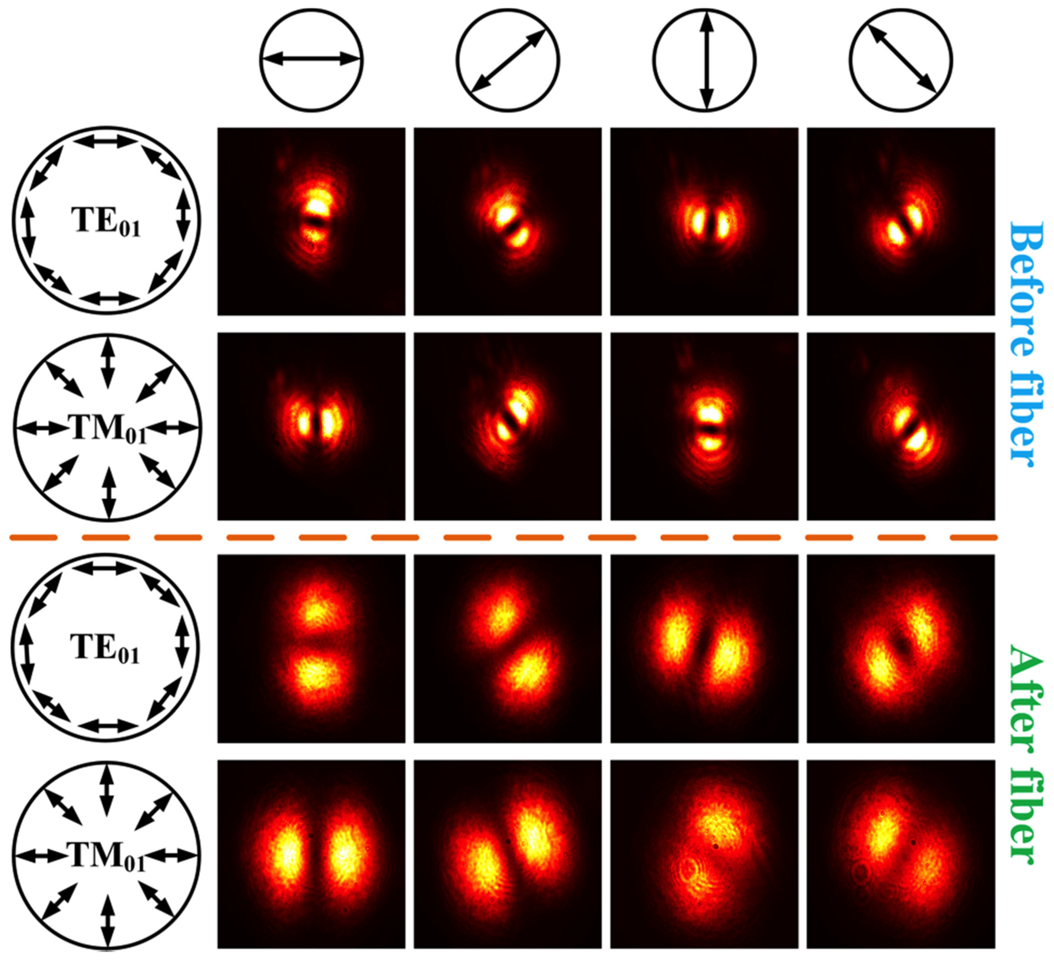
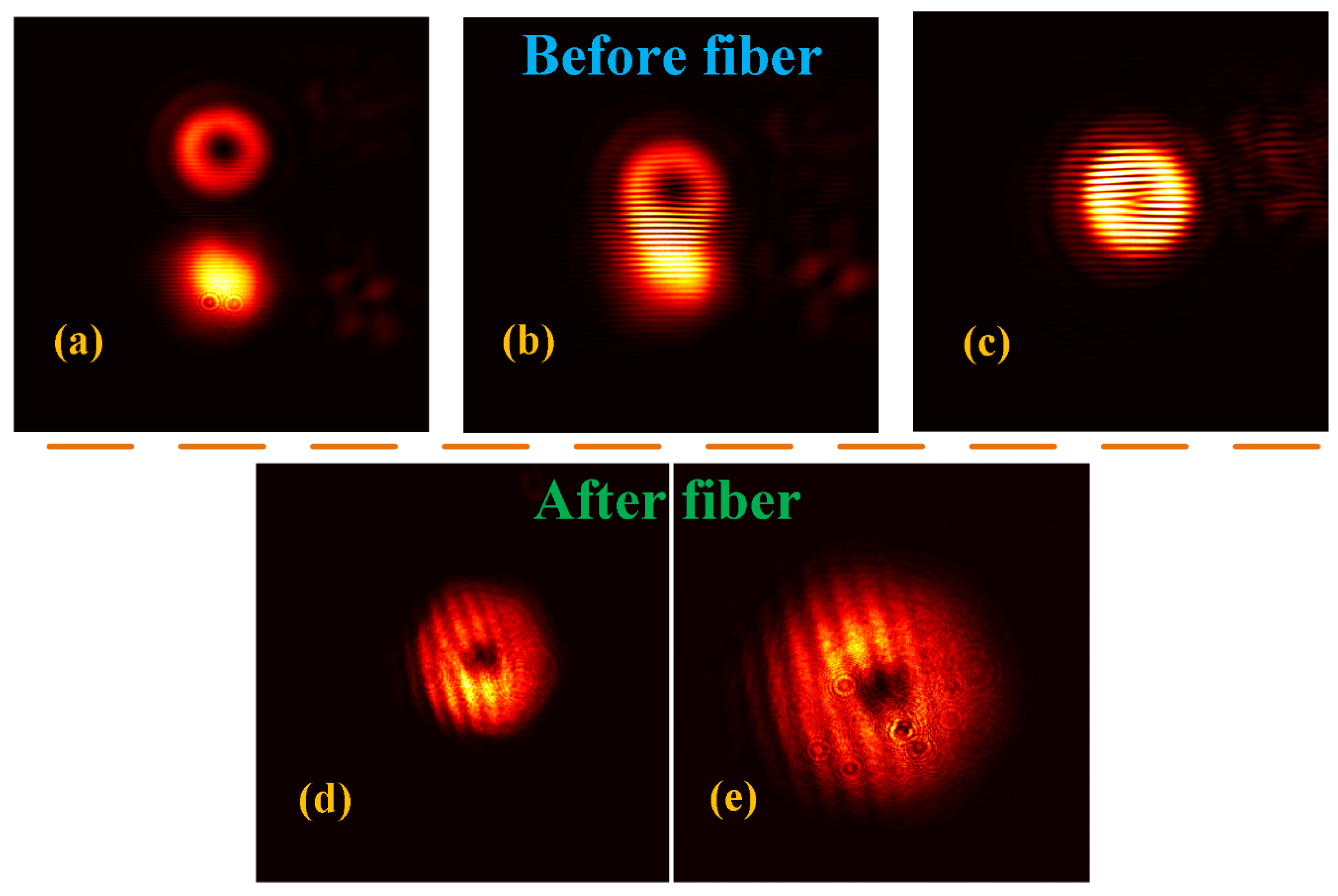
3. Experimental Setup and Discussion

The experimental setup for the transmission and characterization of vector and vortex (CVB and OAM) beams is schematically depicted in Figure 2a,b respectively. Figure 2a shows the setup of OAM (|L| = 1) beam generation and launching, where the Gaussian beam from a tunable laser is collimated using objective lens and followed by a linear polarizer (LP) and a half-wave plate (HWP) for controlling the polarization orientation of the beam. Furthermore, the obtained linearly polarized beam passes through a quarter-wave plate (QWP), which converts the linear state to circular polarization state where the exact sign s = ±1 of circular polarization depends on the orientation of the incident linearly polarized light with respect to the QWP. Next, the S-Plate (i.e., space-variant radial polarization converter from Altechna [30]), designed for operating the wavelength of 815 (±15) nm with more than 85% transmittance, is used to convert circular polarized light into the desired OAM vortex beam.
Later, the obtained OAM (|L| = +1) beam is passed through a 20x and 0.4 NA microscope objective placed on a 6-axis stage in order to launch the vortex beam into the 3-meter long AC-PCF. Another 20x microscope objective lens is placed at the distal end of the fiber to collimate light before imaging on a CCD camera. Figure 2b shows that the experimental setup for the preparation of CVBs is very similar to that of Figure 2a, with the exception that linearly polarized light is launched on the S-Plate (as opposed to circularly polarized) in order to generate TE01 and TM01 beams depending on the orientation of linear polarization with respect to the optical axis of the S-Plate. Hence, polarization parallel to the axis of S-Plate gives TE01 while a perpendicular orientation result in a TM01 beam. Finally, a linear polarizer (i.e., analyzer) is placed between the fiber output and the charge-coupled device (CCD) camera for subsequent vector beam identification [see Figure 3].
The CVB and OAM beam propagation in the AC-PCF is characterized by analyzing their respective intensity profiles at the distal end of the fiber. This was followed by the evaluation of the achieved mode purity after propagation through the fiber. Figure 3 displays the intensity pattern of CVBs imaged after a rotating analyzer used for mode identification of the actual CVB (TE01 or TM01) at hand. The first column in Figure 3 presents a schematic representation of the electric field distribution inside the azimuthally polarized (TE01) and radially polarized (TM01) beams, while the top row indicates the state of rotation angle of the analyzer. By monitoring the intensity profiles of the beams passing through the analyzer (Rows 2–5) with respect to the rotation state of the analyzer, one can identify the type of CVB beam under test [31]. The intensity profiles in the second and third rows of Figure 3 were recorded immediately after the S-Plate and before fiber launching. The fourth and fifth rows of Figure 3 subsequently display the beam intensity profiles after propagation in the three-meter long AC-PCF. The latter images indicate that the output (TM01 and TE01) CV beams retained their polarization after propagation through the AC-PCF.
Figure 4a–c displays the intensity profiles of a vortex and a reference Gaussian beam as they are gradually superposed to create the single fork pattern expected for the interference of a L = +1 helically-phased OAM beam with a tilted reference beam of constant phase front [32,33]. Similarly, Figure 4d,e shows a similar fork interference pattern created by the superposition of a reference Gaussian beam and the vortex beam output from the AC-PCF. More details about the experimental setup and procedure to achieve the interferograms in Figure 4 are provided in the Appendix A. We further note that, prior to our experimental investigation, we measured the laser light coupling efficiency into the AC-PCF for the Gaussian and the vector-vortex beams as 58% and 44%, respectively.
The smaller coupling efficiency of vector-vortex beams is due to the slightly larger input beam diameter (full width at half maximum diameter = 3.81 μm) of the vector-vortex beams at focus compared to the effective core diameter (2a = 3.24 μm) of the AC-PCF. The full width at half maximum (FWHM) diameter of our vector-vortex beams was measured at focus of 20x microscope objected via the knife-edge method [34] using a sharp atomic force microscope (AFM) tip scanned across the doughnut shaped beam in steps of 0.65 micrometer (via a three-axis micro-positioning stage) along the transverse direction. The vortex beam purity was assessed over the whole investigated wavelength range by scanning the single-frequency tunable diode laser (TOPTICA Photonics DL Pro) from 805 nm to 845 nm in steps of 1 nm. The corresponding intensity images of the transmitted OAM beams were then used for evaluating the modal purity based on the azimuthal intensity distribution along the annular beam [more details on the method used for calculating the vortex mode purity is provided in the appendix]. Figure 5 presents the calculated vortex mode purities in dB units as a function of wavelength. The results show that the mode purity varies between 18 and 26 dB, which confirm that good modal purity of vortex modes can be achieved in the fabricated AC-PCF and as can be seen in the sampled intensity profiles shown in Figure 5.

4. Conclusions

In summary, we experimentally demonstrated, for first time, the stable transmission of single radial order singular beams—both polarization cylindrical vector beams (CVB) and the orbital angular momentum (OAM) phase vortex beams—inside a newly designed endlessly mono-radial annular-core photonic crystal fiber (AC-PCF) with sub-micron holey cladding features [27]. The singular beams (OAM and CVBs) were prepared in free space using an S–waveplate and launched in the AC-PCF. Good singular beam purity (up to 26 dB) was demonstrated at the fiber output over the whole investigated wavelength range (805 to 845 nm), spanning a 17 THz bandwidth. This work is another step in the research towards the stable and broadband transmission of singular vector-vortex beams in tailored photonic crystal fibers, and particularly, in designs analogous to the AC-PCF. The results are relevant to applications in space-division multiplexing, quantum communication, sensing via structured light and optical manipulation.

Author Contributions

M.S. and B.U. contributed to the optical fiber design and co-wrote the manuscript. M.S., F.A. and F.B. participated in the experimental demonstration. Y.M. contributed in the fabrication of the fiber. B.U. and F.B. provided primary supervision of the work. All authors contributed to the analysis of the data. All authors have read and agreed to the published version of the manuscript.

Funding

This research was funded by the Natural Sciences and Engineering Research Council of Canada (NSERC) grant I2IPJ 505841-17, and the Fonds de recherche du Quebec-Nature et Technologies (FRQNT) grant 2017-NC-197026.

Acknowledgments

We acknowledge the support of Aligo Innovation in the development of the fiber technology. We thank Patrick Larochelle for helping perform the cutback loss measurements at Laval University.

Conflicts of Interest

The authors declare no conflicts of interest.

Appendix A

Experimental Setup for Generating the Fork Interferogram Pattern of Vortex Beams
Figure A1 shows the schematic of the experimental scheme used for identifying the topological sign and number (L = ±1) of the transmitted vortex beam through the creation of an interference pattern with a Gaussian reference beam on the recording camera. The reference Gaussian beam is obtained by placing a Wollaston prism that separates incident light into two linearly polarized light beams that become circularly polarized upon passing through the quarter-wave plate (QWP). One the ensuing beams is then directed towards the S-Plate to generate the desired L = +1 OAM vortex beam. Further, both OAM and Gaussian beams are then combined using a beams splitter before the corresponding interference pattern can be observed and recorded on the CCD camera. We note that the two interfering beams was progressively brought closer to each other by controlling the orientation of the last three mirrors in the optical path.
Figure A1. Experimental setup for recording the interference pattern of the Gaussian beam (path identified in green) and the vortex OAM beam (path identified in red) on the CCD camera.
Fibers 08 00022 g0a1
This setup was modified to allow the insertion of the fiber between the S-plate and beam splitter (BS) in the OAM beam optical path, so as to enable the characterization of the ensuing fork interferogram after propagation through the AC-PCF under test (in the bottom row of Figure 4).
Mode purity method
To estimate the purity or quality of OAM beam after propagation through fiber in our experimental setup, we used mode purity measurement method based on the variation in azimuthal intensity pattern of optical vortices as performed in [35] where the normalized intensity variation (i.e., the “visibility”) along the azimuthal direction is defined as:
V = I m a x I m i n I m a x + I m i n
Here I m a x and I m i n are the maximum and minimum intensities of the beam along the scanned azimuthal direction. The visibility (V) is then used for evaluating the mode purity as:
Mode   purity   ( d B ) = 10 l o g 10 ( 1 + 1 V V ) 2
Figure A2 depicts the azimuthal intensity distribution (along the dotted black lines) of a typical L = +1 vortex beam generated at 821 nm wavelength with our experimental setup. We note that similar mode purity measurements were performed for the entire investigated wavelength range from 805 to 845 nm.
Figure A2. Azimuthal Intensity distribution of a typical vortex OAM beam at 821 nm (inset image of OAM with azimuthal ring).
Fibers 08 00022 g0a2

References

  1. Zhan, Q. Cylindrical vector beams: From mathematical concepts to applications. Adv. Opt. Photonics 2009, 1, 1. [Google Scholar] [CrossRef]
  2. Allen, L.; Beijersbergen, M.; Spreeuw, R.J.C.; Woerdman, J.P. Orbital angular momentum of light and the transformation of Laguerre-Gaussian laser modes. Phys. Rev. A 1992, 45, 8185–8189. [Google Scholar] [CrossRef] [PubMed]
  3. Yao, A.M.; Padgett, M.J. Orbital angular momentum: Origins, behavior and applications. Adv. Opt. Photonics 2011, 3, 161–204. [Google Scholar] [CrossRef] [Green Version]
  4. Andersen, M.F.; Ryu, C.; Cladé, P.; Natarajan, V.; Vaziri, A.; Helmerson, K.; Phillips, W. Quantized Rotation of Atoms from Photons with Orbital Angular Momentum. Phys. Rev. Lett. 2006, 97, 170406. [Google Scholar] [CrossRef] [PubMed] [Green Version]
  5. Padgett, M.J.; Bowman, R. Tweezers with a twist. Nat. Photonics 2011, 5, 343–348. [Google Scholar] [CrossRef]
  6. Ren, Y.; Li, L.; Wang, Z.; Kamali, S.M.; Arbabi, E.; Arbabi, A.; Zhao, Z.; Xie, G.; Cao, Y.; Ahmed, N.; et al. Orbital Angular Momentum-based Space Division Multiplexing for High-capacity Underwater Optical Communications. Sci. Rep. 2016, 6, 33306. [Google Scholar] [CrossRef]
  7. Willner, A.E.; Huang, H.; Yan, Y.; Ren, Y.; Ahmed, N.; Xie, G.; Bao, C.; Li, L.; Cao, Y.; Zhao, Z.; et al. Optical communications using orbital angular momentum beams. Adv. Opt. Photonics 2015, 7, 66–106. [Google Scholar] [CrossRef] [Green Version]
  8. Bovino, F.A.; Braccini, M.; Bertolotti, M.; Sibilia, C. Management of the orbital angular momentum of vortex beams in a quadratic nonlinear interaction. Opt. Commun. 2011, 284, 2587–2593. [Google Scholar] [CrossRef] [Green Version]
  9. Schmiegelow, C.T.; Schulz, J.; Kaufmann, H.; Ruster, T.; Poschinger, U.; Schmidt-Kaler, F. Transfer of optical orbital angular momentum to a bound electron. Nat. Commun. 2016, 7, 12998. [Google Scholar] [CrossRef]
  10. Brullot, W.; Vanbel, M.K.; Swusten, T.; Verbiest, T. Resolving enantiomers using the optical angular momentum of twisted light. Sci. Adv. 2016, 2, e1501349. [Google Scholar] [CrossRef] [Green Version]
  11. Youngworth, K.; Brown, T. Focusing of high numerical aperture cylindrical-vector beams. Opt. Express 2000, 7, 77. [Google Scholar] [CrossRef] [PubMed]
  12. Kozawa, Y.; Matsunaga, D.; Sato, S. Superresolution imaging via superoscillation focusing of a radially polarized beam. Optica 2018, 5, 86–92. [Google Scholar] [CrossRef]
  13. Drevinskas, R.; Zhang, J.; Beresna, M.; Gecevičius, M.; Kazanskii, A.G.; Svirko, Y.P.; Kazansky, P. Laser material processing with tightly focused cylindrical vector beams. Appl. Phys. Lett. 2016, 108, 221107. [Google Scholar] [CrossRef] [Green Version]
  14. Kozawa, Y.; Sato, S. Optical trapping of micrometer-sized dielectric particles by cylindrical vector beams. Opt. Express 2010, 18, 10828–10833. [Google Scholar] [CrossRef]
  15. Brunet, C.; Rusch, L.A. Optical fibers for the transmission of orbital angular momentum modes. Opt. Fiber Technol. 2017, 35, 2–7. [Google Scholar] [CrossRef] [Green Version]
  16. Brunet, C.; Ung, B.; Wang, L.; Messaddeq, Y.; LaRochelle, S.; Rusch, L.A. Design of a family of ring-core fibers for OAM transmission studies. Opt. Express 2015, 23, 10553–10563. [Google Scholar] [CrossRef]
  17. Brunet, C.; Vaity, P.; Messaddeq, Y.; LaRochelle, S.; Rusch, L.A. Design, fabrication and validation of an OAM fiber supporting 36 states. Opt. Express 2014, 22, 26117–26127. [Google Scholar] [CrossRef]
  18. Gregg, P.; Kristensen, P.; Ramachandran, S. Conservation of orbital angular momentum in air-core optical fibers. Optica 2015, 2, 267. [Google Scholar] [CrossRef] [Green Version]
  19. Ramachandran, S.; Gregg, P.; Kristensen, P.; Golowich, S.E. On the scalability of ring fiber designs for OAM multiplexing. Opt. Express 2015, 23, 3721–3730. [Google Scholar] [CrossRef]
  20. Ramachandran, S.; Kristensen, P.; Yan, M.F. Generation and propagation of radially polarized beams in optical fibers. Opt. Lett. 2009, 34, 2525–2527. [Google Scholar] [CrossRef] [Green Version]
  21. Zhang, H.; Zhang, X.; Li, H.; Deng, Y.; Xi, L.; Tang, X.; Zhang, W. The Orbital Angular Momentum Modes Supporting Fibers Based on the Photonic Crystal Fiber Structure. Crystals 2017, 7, 286. [Google Scholar] [CrossRef] [Green Version]
  22. Zhang, L.; Zhang, K.; Peng, J.; Deng, J.; Yang, Y.; Ma, J. Circular photonic crystal fiber supporting 110 OAM modes. Opt. Commun. 2018, 429, 189–193. [Google Scholar] [CrossRef]
  23. Pakarzadeh, H.; Sharif, V. Control of orbital angular momentum of light in optofluidic infiltrated circular photonic crystal fibers. Opt. Commun. 2019, 438, 18–24. [Google Scholar] [CrossRef]
  24. Tandje, A.; Yammine, J.; Bouwmans, G.; Dossou, M.; Vianou, A.; Andresen, E.R.; Bigot, L. Design and Fabrication of a Ring-Core Photonic Crystal Fiber for Low-Crosstalk Propagation of OAM Modes. In Proceedings of the 2018 European Conference on Optical Communication (ECOC), Rome, Italy, 23–27 September 2018; pp. 1–3. [Google Scholar]
  25. Hu, Z.-A.; Huang, Y.-Q.; Luo, Z.-C.; Cui, H.; Xu, W.-C. Photonic crystal fiber for supporting 26 orbital angular momentum modes. Opt. Express 2016, 24, 17285. [Google Scholar] [CrossRef] [PubMed]
  26. Yue, Y.; Zhang, L.; Yan, Y.; Ahmed, N.; Yang, J.-Y.; Huang, H.; Ren, Y.; Dolinar, S.; Tur, M.; Willner, A.E. Octave-spanning supercontinuum generation of vortices in an As2S3 ring photonic crystal fiber. Opt. Lett. 2012, 37, 1889–1891. [Google Scholar] [CrossRef] [PubMed]
  27. Sharma, M.; Pradhan, P.; Ung, B. Endlessly mono-radial annular core photonic crystal fiber for the broadband transmission and supercontinuum generation of vortex beams. Sci. Rep. 2019, 9, 2488. [Google Scholar] [CrossRef] [Green Version]
  28. Tandjè, A.; Yammine, J.; Dossou, M.; Bouwmans, G.; Baudelle, K.; Vianou, A.; Andresen, E.R.; Bigot, L. Ring-core photonic crystal fiber for propagation of OAM modes. Opt. Lett. 2019, 44, 1611–1614. [Google Scholar] [CrossRef]
  29. Zhu, Z.; Brown, T. Analysis of the space filling modes of photonic crystal fibers. Opt. Express 2001, 8, 547–554. [Google Scholar] [CrossRef]
  30. Altechna. Available online: https://www.altechna.com/products/s-waveplate-radial-polarization-converter/ (accessed on 3 April 2020).
  31. Pradhan, P.; Sharma, M.; Ung, B. Generation of Perfect Cylindrical Vector Beams with Complete Control over the Ring Width and Ring Diameter. IEEE Photonics J. 2018, 10, 1–10. [Google Scholar] [CrossRef]
  32. Zhang, H.; Mao, B.; Han, Y.; Wang, Z.; Yue, Y.; Liu, Y.-G. Generation of Orbital Angular Momentum Modes Using Fiber Systems. Appl. Sci. 2019, 9, 1033. [Google Scholar] [CrossRef] [Green Version]
  33. Gecevicius, M.; Ivanov, M.; Beresna, M.; Matijosius, A.; Tamulienė, V.; Gertus, T.; Cerkauskaite, A.; Redeckas, K.; Vengris, M.; Smilgevicius, V.; et al. Toward the generation of broadband optical vortices: Extending the spectral range of a q-plate by polarization-selective filtering. J. Opt. Soc. Am. B 2017, 35, 190–196. [Google Scholar] [CrossRef]
  34. Siegman, A.; Sasnett, M.; Johnston, T. Choice of clip levels for beam width measurements using knife-edge techniques. IEEE J. Quantum Electron. 1991, 27, 1098–1104. [Google Scholar] [CrossRef]
  35. Bozinović, N.; Kristensen, P.; Ramachandran, S. Long-range fiber-transmission of photons with orbital angular momentum. In Proceedings of the Conference on Lasers and Electro-Optics, Munich, Germany, 22–26 May 2011; p. 1. [Google Scholar]
Figure 1. (a) Cutback losses of the used annular core photonic crystal fiber (AC-PCF), where the scanning electron microscope (SEM) image of the actual AC-PCF is shown in inset. (b) V-parameter of the AC-PCF as a function of the input wavelength in the 300–1800 nm range as calculated with finite-element method (FEM) simulations.
Fibers 08 00022 g001
Figure 2. Experimental setup for launching and imaging (a) orbital angular momentum (OAM) beams and (b) cylindrical vector beams (CVB) (TE01 and TM01) in the AC-PCF.
Fibers 08 00022 g002
Figure 3. Experimental identification of the obtained CVBs (radial TM01 and azimuthal TE01) before (top two rows) and after propagation in the AC-PCF (bottom two rows) through rotation of the analyzer positioned in front of the CCD camera.
Fibers 08 00022 g003
Figure 4. (ac) Interference pattern of a L = +1 doughnut-shaped OAM beam with a reference Gaussian beam as they progressively merge to generate a single fork pattern before (Top row) and (d,e) after propagation in the fiber (Bottom row).
Fibers 08 00022 g004
Figure 5. Mode purity of OAM beam at fiber output as a function of wavelength (from 805 to 845 nm in step on 1 nm using tunable laser), Inset: output beam images for selected wavelengths.
Fibers 08 00022 g005

