Article

Development and Multiscale Characterization of 3D Warp Interlock Flax Fabrics with Different Woven Architectures for Composite Applications

ENSAIT, GEMTEX—Laboratoire de Génie et Matériaux Textiles, F-59000 Lille, France
*
Author to whom correspondence should be addressed.
Fibers 2020, 8(2), 15; https://doi.org/10.3390/fib8020015
Submission received: 21 December 2019 / Revised: 31 January 2020 / Accepted: 12 February 2020 / Published: 18 February 2020

Abstract

:
Multiscale characterization of the textile preform made of natural fibers is an indispensable way to understand and assess the mechanical properties and behavior of composite. In this study, a multiscale experimental characterization is performed on three-dimensional (3D) warp interlock woven fabrics made of flax fiber on the fiber (micro), roving (meso), and fabric (macro) scales. The mechanical tensile properties of the flax fiber were determined by using the impregnated fiber bundle test. The effect of the twist was considered in the back-calculation of the fiber stiffness to reveal the calculation limits of the rule of mixture. Tensile tests on dry rovings were carried out while considering different twist levels to determine the optimal amount of twist required to weave the flax roving into a 3D warp interlock. Finally, at fabric-scale, six different 3D warp interlock architectures were woven to understand the role of the architecture of binding rovings on the mechanical properties of the dry 3D fabric. The results reveal the importance of considering the properties of the fiber and roving at these scales to determine the more adequate raw material for weaving. Further, the characterization of the 3D woven structures shows the preponderant role of the binding roving on their structural and mechanical properties.

1. Introduction

Three-dimensional (3D) woven composites have shown great potential in aerospace and automotive applications due to near net shape, high structural integrity, and low manufacturing costs [1,2,3]. Compared with two-dimensional (2D) fiber reinforcements, 3D woven fabrics consist of layers of warp and weft tows interlaced in the through-thickness direction by weaver tows, which are called binding warp tows. Thanks to the through-the-thickness fiber reinforcement, 3D woven composites exhibit higher damage tolerance, higher inter-laminar performance, and elevated impact resistance [4,5,6]. Many previous works have characterized the mechanical properties of these composites, especially on the effect of weave parameters on the mechanical properties of 3D woven composites. On 3D layer-to-layer glass woven composite structures [7], Dahale et al. shows that the mechanical properties were improved by the decreased crimp and increased fiber content. Mahadik et al. [8] described the effect of fabric compaction and yarn waviness on the mechanical properties of an angle-interlock 3D woven composite. Results showed that in the warp direction, the proportion of high-crimp areas determined the final failure stress and failure initiated in a highly crimped area. Behera et al. [9] performed a detailed experimental study on in-plane tensile, compressive, bending, and impact resistance of various 3D woven composites. They demonstrated that the 3D angle interlock composite possesses the highest stress, followed by the warp interlock and orthogonal composites. These works showed that the architecture of the reinforcement has a preponderant role on the mechanical properties of the composite.
Generally, 3D architectures can be obtained by combining multi-layers of stacked 2D fabric with a through-the-thickness fiber reinforcement, introduced using stitching, z-pining, or tufting technologies [10,11,12]. Another technology is the 3D warp interlock weaving, in which multi-layers of in-plane yarns are bound together by a group of binding warp yarns according to a specific architecture (light blue in Figure 1) [13]. Consequently, in 3D warp interlock weaving, a thick structure is formed without degradation to the in-plane fibers that results from needle insertion through-the-thickness in the stitching and tufting techniques. Moreover, the fiber reinforcement through-the-thickness direction is inserted during the weaving and no further steps are required.
Boussu et al. [13] proposed a general definition of 3D warp interlock fabric. Their definition will be used throughout the paper to describe the fabrics, as following: “X1X2 N Y1-Y2 Binding {Pattern} {#} Stuffer {#}”. The first two parameters define the type of binding: with X1 the type of angle of binding (angle (A) or orthogonal (O)) and with X2 the type of depth of binding (layer-to-layer (L) or through-the-thickness (T)). The third parameter N gives the number of layers of weft yarns. The fourth, fifth, and sixth parameters (Y1, Y2, “Pattern”) define the weaving pattern of the binding warp yarn, with Y 1 the step of the binding warp yarn and Y2 the depth of the binding warp yarn, and “Pattern” the weave diagram of the binding warp yarns with the weft yarns. Lastly, hash ( # ) defines the position of the stuffer warp yarns in the structure. Some examples of the full description of 3D warp interlock structures are given in Appendix A. Weaving parameters (such as the speed, the shape of the shed, etc.) must be also adjusted to reduce frictional forces between the juxtaposed warp yarns during weaving [14]. The 3D warp interlock weaving allows improving the fiber ratio by adding layers. The impacts of other parameters of the 3D warp interlock structure on its properties were studied in previous works of the authors, including the type of binding [15] or the number of layers [16].
To provide a sustainable and environmentally-friendly alternative to the glass fiber composite, the use of natural fibers is the subject of a large number of studies. The natural fibers offer the advantages of low density, renewability, and biodegradability over glass fiber [17,18]. From flax yarns, Jabbar et al. [19] wove four 3D warp interlock fabrics with variation in binding point density of the binding warp yarns. They noted that the binding point density between layers improves the out-of-plane properties at the expense of the in-plane properties. From jute yarns, Kashif et al. [20] made about 10 3D warp interlock preforms and have concluded, via an ANOVA, that the weave pattern has an impact on mechanical properties of the dry fabric. To improve the mechanical properties of 3D warp interlock composites based on natural fibers, it is essential to control the parameters of the reinforcement architecture, but also to follow the properties at each scale [21,22], because the mechanical properties of plant fibers are often considered to show high variability [23].
This study aims to investigate the effect of the weave pattern of 3D warp interlock flax fabric on its structural and mechanical properties. For this purpose, six different 3D warp interlock fabrics with different depths of binding and different weave patterns of binding warp yarns were woven. Further, in order to select the adequate raw material for weaving processes, a multi-scale experimental study was conducted, which involved characterizing the tensile properties of the flax fiber and identifying the impact of the twist level of the roving on its mechanical performance.

2. Materials and Methods

2.1. Fiber Characterization

The impregnated fiber bundle test (IFBT) is one of the used techniques to determine the tensile properties of natural fibers, which are characterized by their discrete length [24]. The tensile test was performed on an impregnated bundle of juxtaposed fibers. The back-calculation technique was then applied to deduce the stiffness and strength of the individual fiber from the measured tensile properties of the composite. The average tensile properties of the tested fibers was obtained in this test, instead of testing each fiber in the single fiber tensile, which is a time consuming and too delicate test regarding the fiber extraction and installing of fibers on the tensile machine grips.
The IFBT was used to identify the influence of the roving twist on the tensile properties of the fibers. Flax roving of 1000 Tex was tested with different twist levels varying from 0 to 170 tpm. The roving was provided by Depestele Group and was cropped in Normandy, France. At each twist level, four samples were tested. Rovings were impregnated (by hand) with an epoxy resin (SR8200/SD7204) provided by Sicomin. The size of the IFBT sample was 250 × 10 mm2, and the tensile tests were performed on an Instron 5985 tensile machine with a load cell of 250 kN. The gauge length was set to 150 mm and the speed test was set to 1 mm/min. The sample weight allowed us to check the proportion of each constituent, thanks to the modified rule of mixture, and to determine the stiffness of the fibers, which constitute the roving. The modified rule of mixture was used in this study in order to deduce the stiffness of the fibers, Equation (1) [25]. Contrary to the standard rule of mixture, this one took into consideration the orientation and length of the fiber and the porosity.
E c = ( η 0 η 1 V f E f + V m E m ) ( 1 V p ) n
where η 0 is the fiber orientation efficiency factor, η 1 is the fiber length efficiency factor, n is the porosity efficiency exponent, and E , V is the modulus and volume fraction of each the constituents f , m , c , and p (for fiber, matrix, composite, and porosity, respectively). The fiber orientation efficiency factor is calculated from Equation (2a,b) [25,26]:
η 0 = cos 2 ( 2 tan 1 ( 10 3 · T 4 π · L ρ · ϕ ) )
ϕ = 0.7 ( 1 0.78 e 0.195 · T )
where L is the linear density in Tex, ρ is the density of the fiber in kg/m3 (selected to 1.504 for flax fiber in this paper), and T is the twist level in tpm (turns per meters).

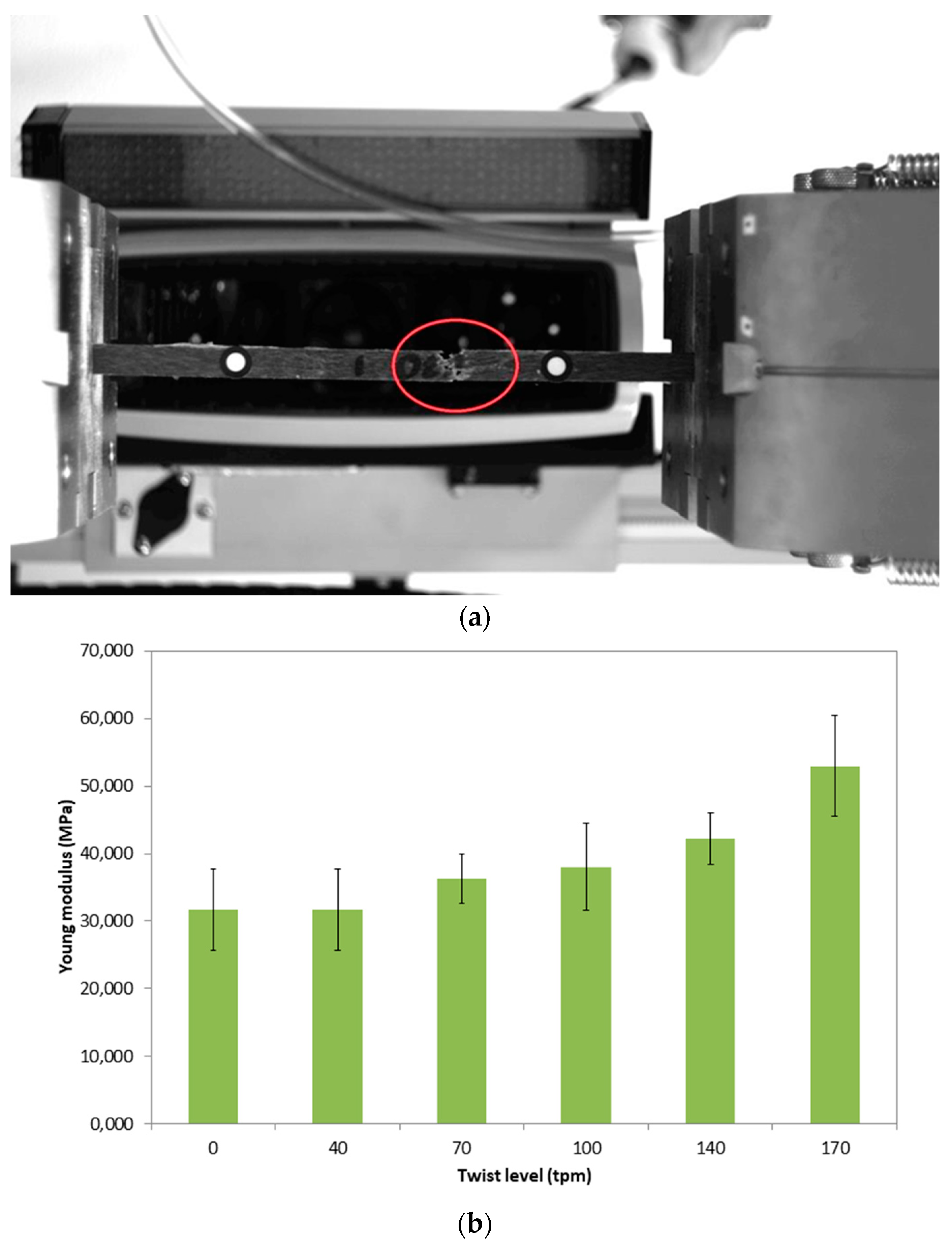
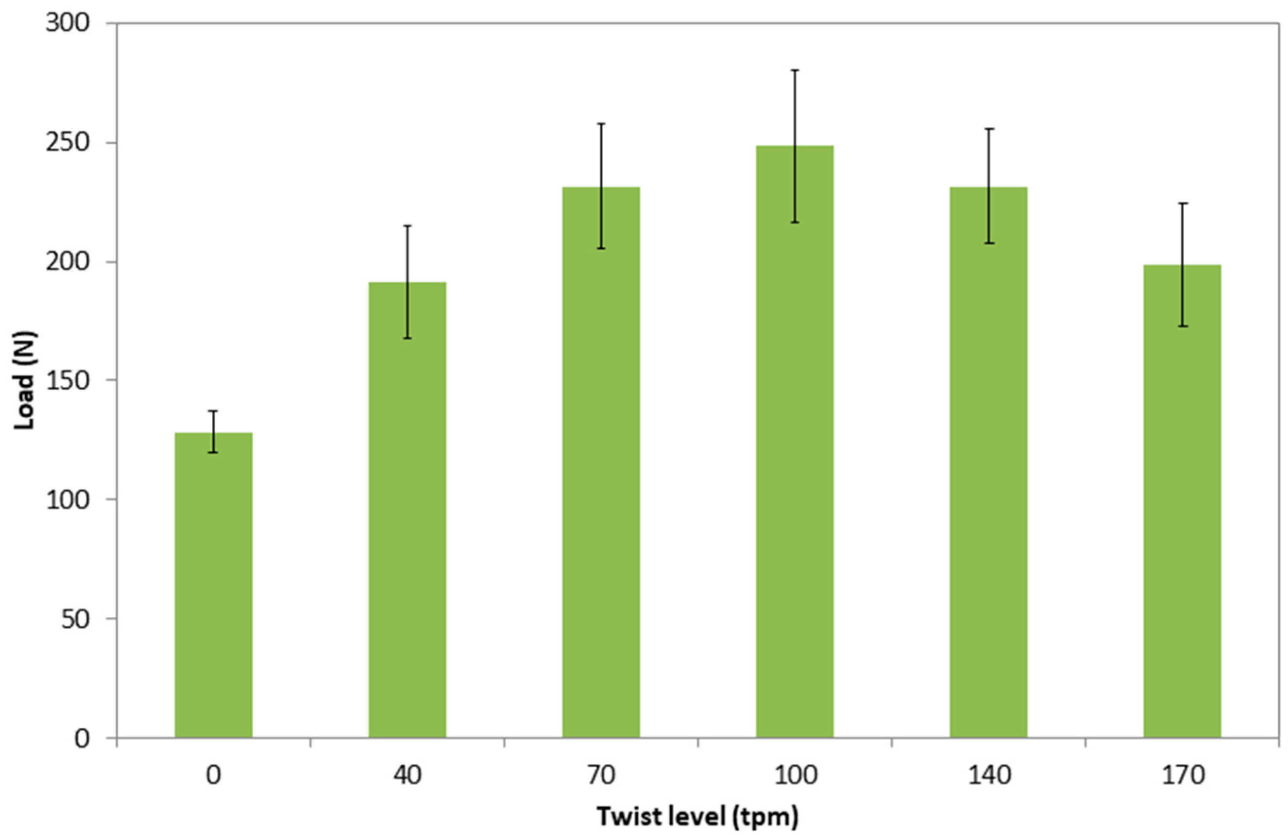
2.2. Roving Characterization

On the weaving loom, the dry rovings have to sustain an extensional effort necessary for the shed formation and avoid the inter-rovings sticking. Therefore, the tensile test was performed on the provided roving to analyze the influence of the twist on their mechanical properties and to determine the most adequate twist level to proceed to the weaving process. The prepared roving for the IFBT test with the announced twist level was tested again in the dry state on an MTS Criterion tensile machine with a load cell of 10 kN. The gauge length and the speed test were set to 200 mm and 100 mm/min, respectively. Twist levels were checked after the twisting process, according to the ISO 2061 standard.

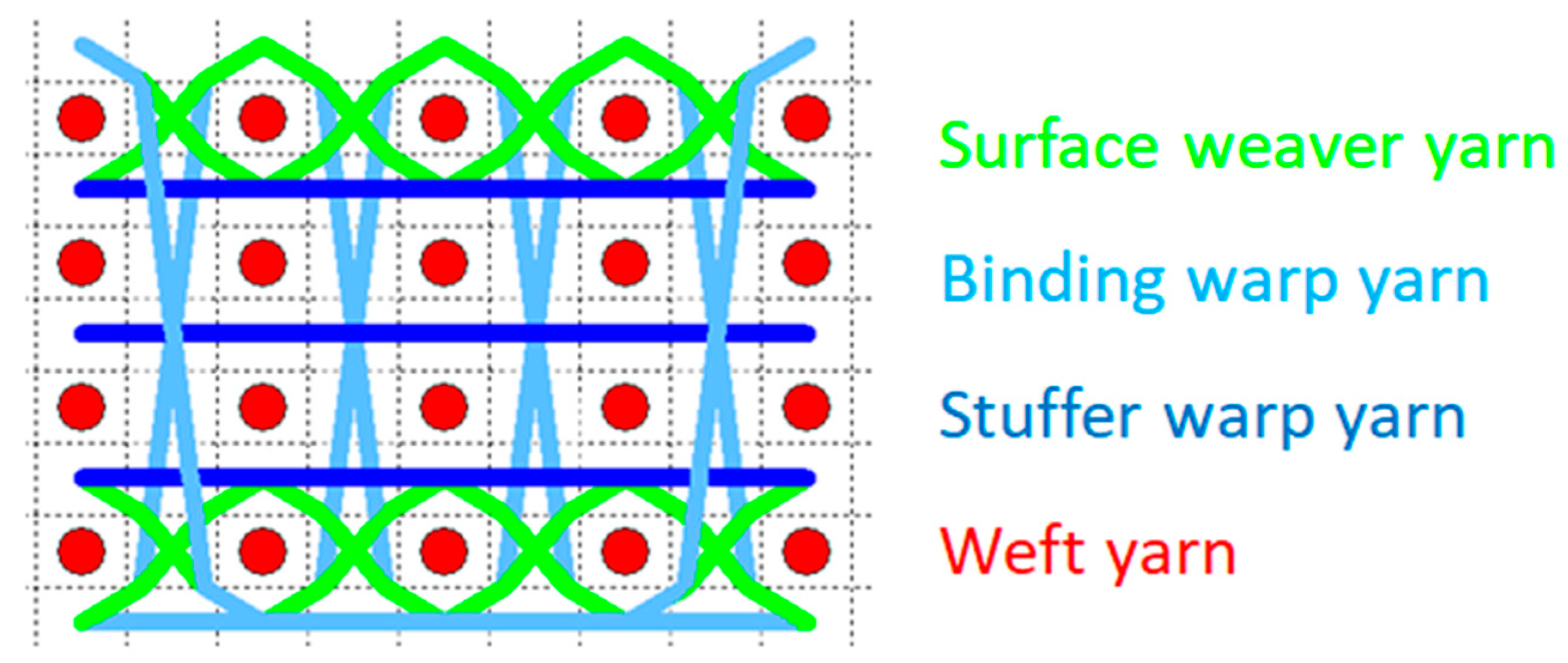
2.3. Architecture Selection
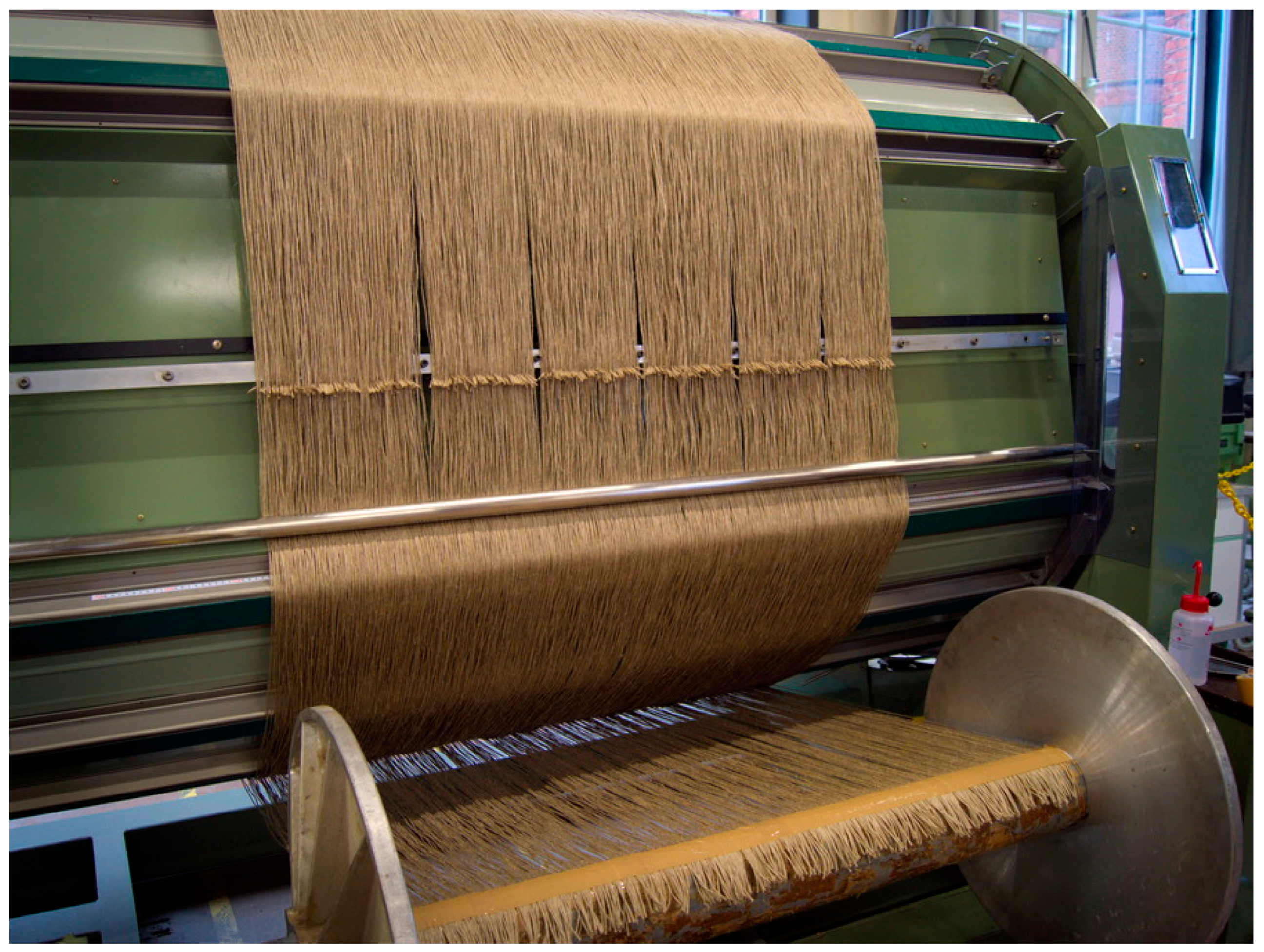
In order to analyze both effect of twill and depth of binding, a two-factor experimental design was established. The jaw effect was obtained by the coupling warp effect and weft effect. The jaw effect can be applied on twill and sateen fabric, as well as on 3D warp interlock, based on these two first combinations. Twill 4 weave for the binding warp yarns was considered for the six selected 3D warp interlock structures given in Table 1. Depth of binding varies from 5 to 3. When the depth of binding was equal to the number of layers, the weave pattern of the binding was named through-the-thickness (T5). Otherwise, when it was inferior, the weave pattern was named layer-to-layer (L4 and L3). The complete identification codes of the fabrics, according to the definition by Boussu et al. [13], are given in Appendix A.

2.4. Weaving

Two warp beams were produced with the selected level of twist on a Suzuki warping machine (Figure 2). One beam was dedicated for the binding warp roving and the other for the stuffer warp roving. The length of the rovings on the two beams was not the same, since the two rovings were consumed differently. The binding warp rovings were more consumed due to their longer path through the fabric thickness in comparison with the stuffer, which is kept relatively straight inside the structure. The final warp density, obtained after warping and drawing in, was 6 rovings/cm. The weaving was carried out on a Dornier dobby loom at a speed of 75 picks/min. The weft density was set to 10 rovings/cm (either 2 columns/cm).

2.5. Fabric Characterization

The produced 3D warp interlock fabrics were characterized at a dry state (un-impregnated with matrix). Warp and weft densities were checked after weaving, according to the ISO 4602 standard. Crimp of the constituting rovings inside the fabrics was measured separately for each layer, as defined in the ISO 7211-3 standard. Thickness and areal density of the produced fabrics were checked, according to ISO 4603 and ISO 12127 standards, respectively. Flexural rigidity of the fabric in the warp direction was evaluated via cantilever test, according to the ISO 9073-3 standard. This test was based on determining the bending length of the fabric, at which the horizontally-hanged sample fell under its own weight and touched a plane inclined at 41.5 ° . Flexural rigidity of the produced fabrics in the weft direction couldn’t be measured, because of their high rigidity brought by the high density of the weft rovings. At least 20 measurements were performed for each test described previously. The tensile test was performed on an Instron 5980 machine with a load cell of 250 kN. Five samples were tested in both fabric material directions (warp and weft) with the following dimensions: 300 × 50 mm2. The gauge length was 200 mm and the speed of machine crosshead was set to 100 mm/min.

3. Results and Discussion

3.1. Fiber Characterization

According to the linear density and the twist level of the roving, the fiber orientation efficiency factor η 0 was calculated and ranged from 0.50 (for a twist of 170 tpm) to 1 (for untwisted roving). The fiber length efficiency factor η 1 was set to 1, as reported in [25], and for fibers, their L D ratio exceeded 50, since the used flax fiber attained a ratio up to 2000 [27]. The porosity efficiency coefficient was set to 2, as confirmed by Madsen et al. [25] for the plant fiber composite. Figure 3a shows a sample at the end of the tensile test. The break is visible at the center of the sample. Figure 3b displays the average value, with standard deviation, of the back-calculated elastic modulus of the fibers, according to the modified rule of mixtures (Equation (1)). For the twist levels located between 0 and 100 tpm, the modified rule of mixture returns the same elastic modulus for the flax fiber (about 30 GPa) without a significant statistical difference. This result coincides with the published values in the literature [24,28]. However, the modified rule of mixtures reaches its limit for the samples twisted to 140 and 170 tpm. Once the twist level exceeded 140 tpm, η 1 led to overcompensating the stiffness of the fiber.

3.2. Roving Characterization

The linear density of the roving used in this study was 1000 Tex. Figure 4 shows the load at break of dry rovings submitted to the same twist levels of roving in the IFBT test. It can be concluded that by increasing the twist level, the load at break increases until at a critical threshold, from which the load decreases. Similar results were observed by Ma et al. [29] on sisal fibers. Below 100 tpm, the induced a twist to the roving leads to improve the cohesion between the fibers by compacting the roving and increasing the load at break. Beyond 100 tpm, the impact of misalignment of the fiber in the roving relative to the load axis manifests in decreasing of the breaking load. Based on these results and regarding the required tenacity for the roving on weaving loom without damaging the roving permeability properties for composite manufacture, 40 tpm was selected for preparing the roving to weave the six 3D warp interlock fabrics.

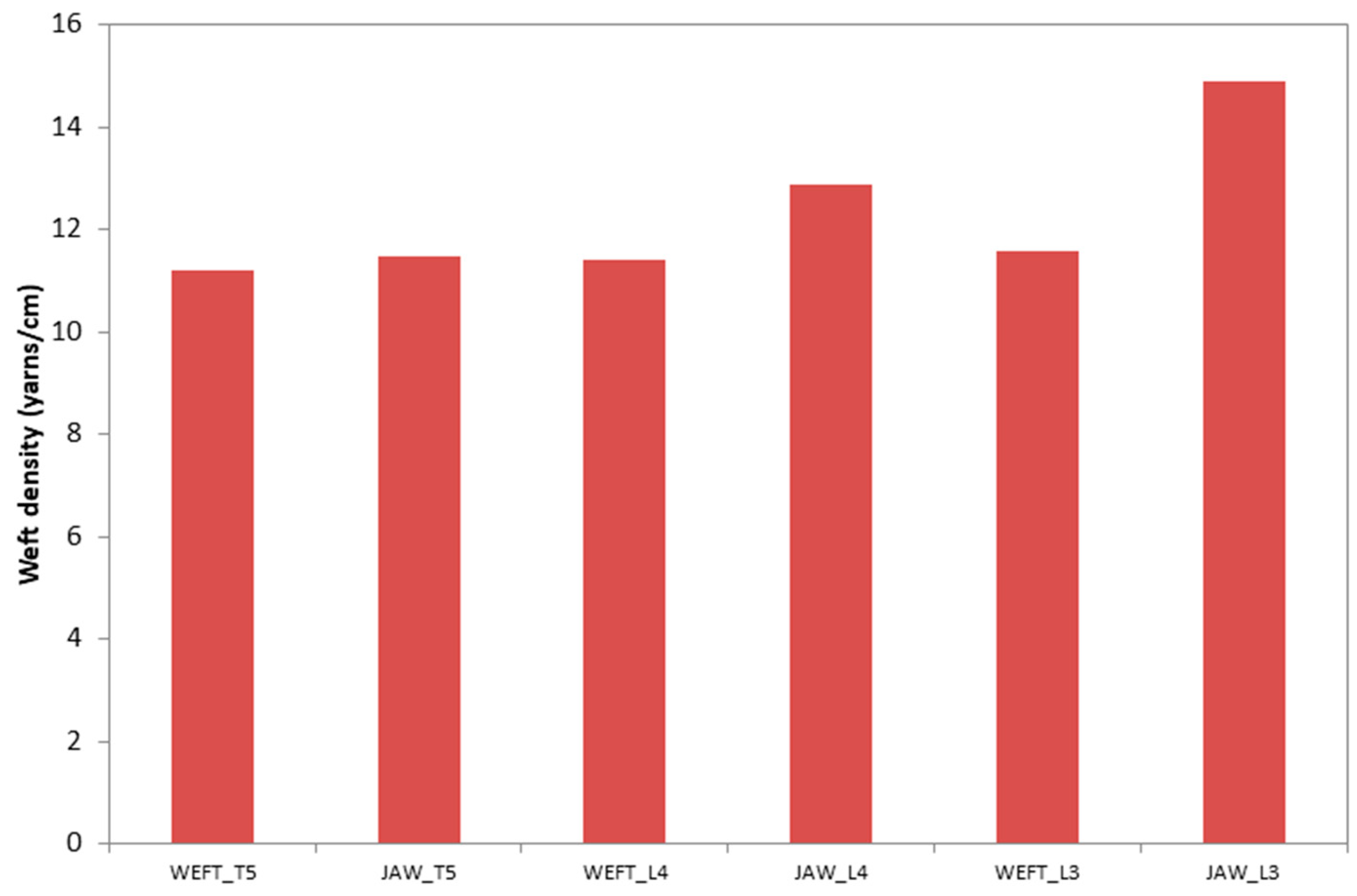
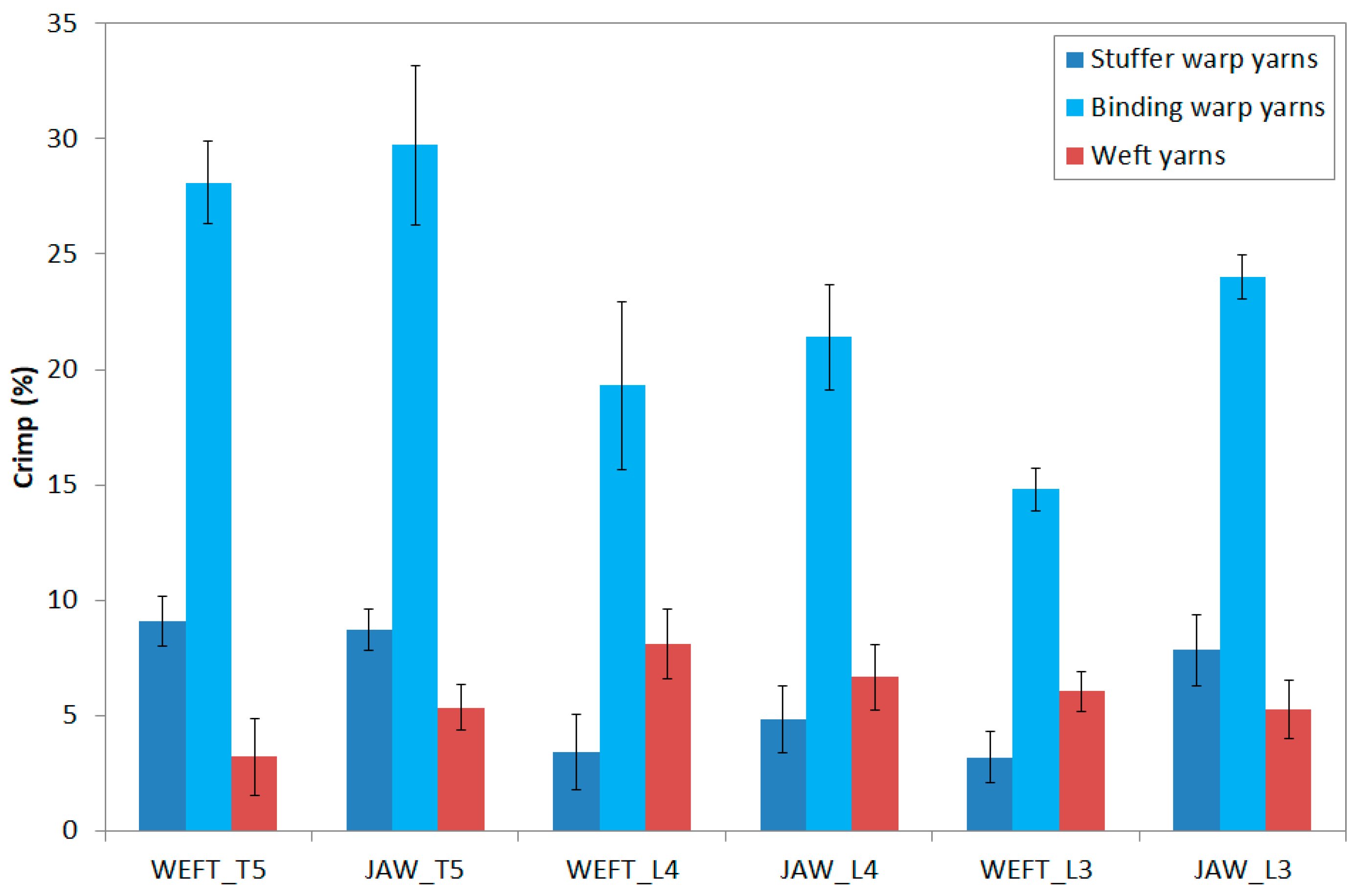
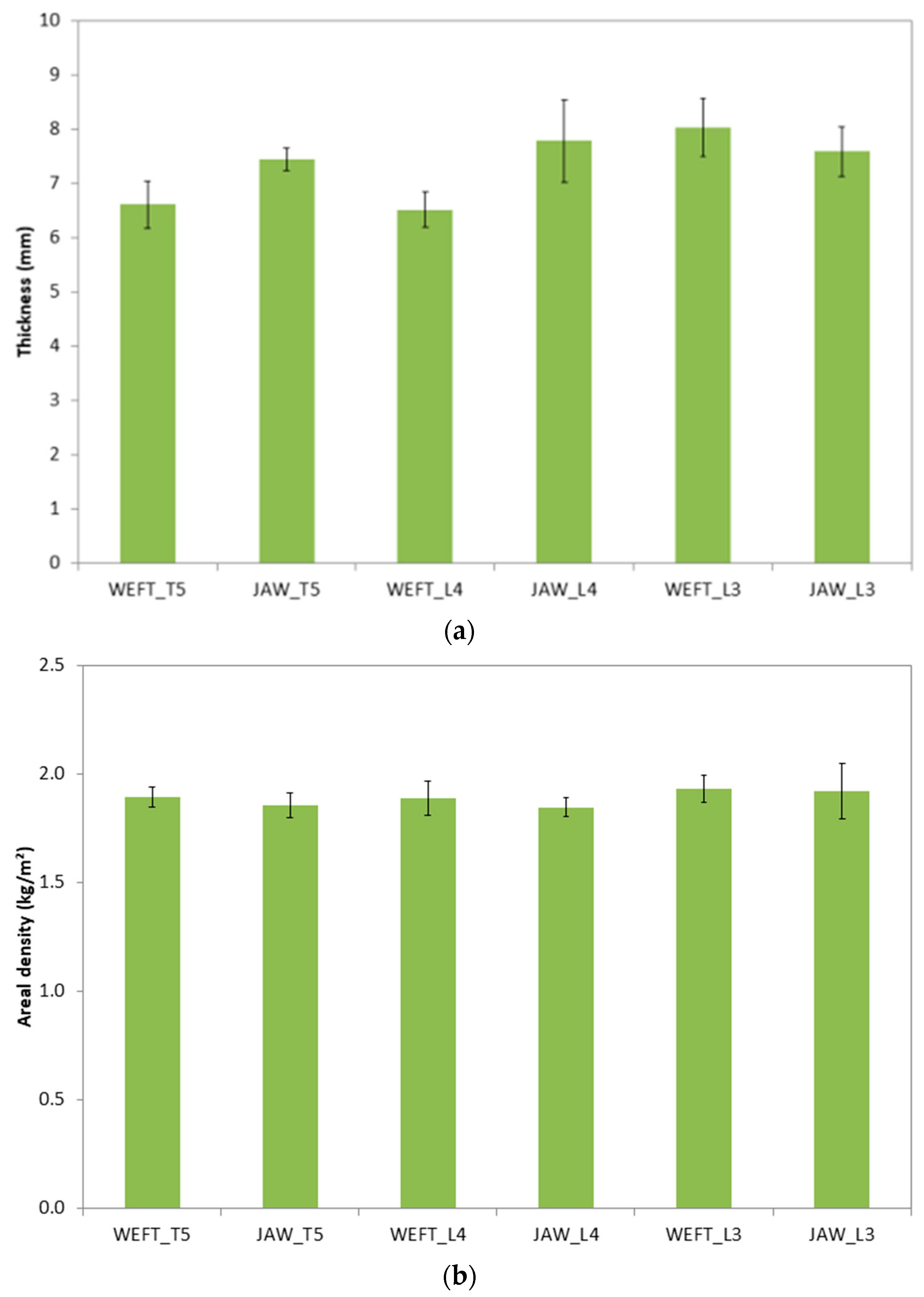
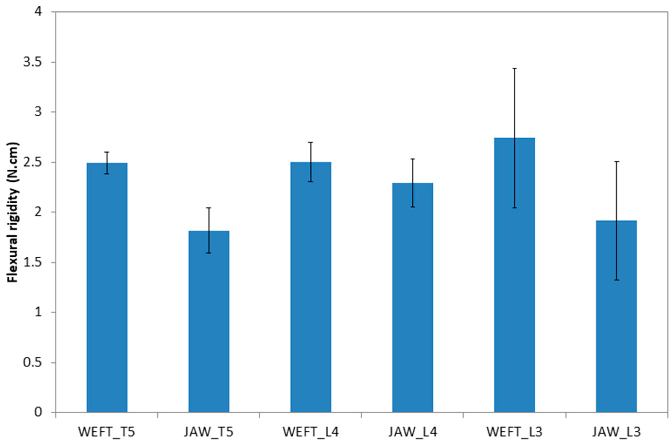
3.3. Fabric Characterization

Warp and weft densities results
Warp density is defined during the warping and confirmed with the weaving reed density and number of warp yarns per dent. On the weaving loom, the density of stuffer and binding warp yarns were set to 4 yarns/cm and 2 yarns/cm, respectively, while the density of the weft yarns was set on the loom to insert 10 yarns/cm (2 columns/cm). The weft density was measured on the six produced fabrics, as shown in Figure 5. A slight difference was observed in the measured values on the fabrics in comparison with the set value on the loom. This difference manifested in higher density of fabric after weaving was explained by the difficulties related to packing and taking up operations on the weaving loom for thick fabrics. Moreover, the jaw effect seemed to increase the yarn density by trapping the weft yarns. Depth of the binding warp yarns seemed to decrease the weft density. With increasing binding depth, the number of trapped weft yarns increased and, consequently, were able to deform more and reduce the place to fill with other yarns.
Warp and weft crimp results
Figure 6 displays crimps of the three types of yarns for the six fabrics. Crimp of the binding warp yarn increased by coupling the two effects on twill weave (JAW). In order to confine weft yarns, a more important length of binding warp yarns was required. Additionally, crimp of the binding warp increased with the depth of binding. This result was consistent with the literature [30] and a previous study [15]. The less the bound layers was, the less the required yarns quantity was. The crimp of stuffer warp yarns was slightly higher for the jaw effect. As binding warp yarns trapped weft yarns, the undulation of the stuffer warp yarn increased slightly. Additionally, crimp of the stuffer warp yarns differed with the binding depth. Through-the-thickness (T5) structure showed a higher crimp for the stuffer warp yarn than the layer-to-layer structure (L4 and L3). Finally, crimp of the weft yarn evolved in order to stabilize the structures.
Thickness and areal density results
Figure 7a,b displays, respectively, the thickness and the areal density of each structure. The jaw structures were slightly thicker than the weft effect. The coupling of warp and weft confined weft yarns, which were forced to keep their position in the structure (one over the other). With a lower depth of binding, thickness of the fabric increased, because float of the twill effect created an over-thickness through the layers. The only difference in areal density was caused by the difference in density of weft yarns (Figure 5) and crimp of the binding warp yarns (Figure 6), but was not significant.
Flexural rigidity results in warp direction
Figure 8 displays flexural rigidity of the produced fabrics in the warp direction. The jaw effect, by partitioning weft yarns, allowed decreasing of the flexural rigidity in the warp direction. Otherwise, no significant difference in flexural rigidity was noted between the fabrics, with varying binding depth in the warp direction, to the accuracy of the standard deviation. As mentioned above, the tests unfortunately could not be carried out in the weft direction, because the high rigidity of the fabric in this direction attributed to a high density and low crimp of the weft yarn.
Tensile test results
Figure 9a shows an example of load-elongation curves of textile tests performed on the dry fabrics. All samples were cut on the fabric with the same number of rovings in the test direction. Two peaks were observed on the obtained curve, indicating distinctive rupture of the two types of stuffer and binding warp yarns. This phenomenon was attributed to the difference in the crimp ratio of the two yarns. The stuffer warp yarn with a lower crimp broke at a lower elongation, whereas the binding warp yarn required higher elongation to be maximally extended in the structure before rupture. Bandaru et al. [31] noticed a similar shape for the load-elongation curve of the 3D warp interlock fabric made with para-aramid yarns (Kevlar ©).
The maximum loads at break of the two types of warp yarn in the different produced structures referred to the number of yarns crossover sample widths, which are displayed in Figure 9b. The difference in maximum load between stuffer and binding warp yarns was attributed to the different numbers of each type of yarns in the structures. To weave the structures, proportions of binding/stuffer warp was set to 1/2. The recorded maximum load seemed higher for structures bound using through the thickness pattern (T5). In the two woven structures with this pattern (WEFT_T5 and JAW_T5), the higher value of breaking load was induced by confining weft yarns by warp yarn on the two fabric surfaces, resulting in higher inter-yarns friction. Otherwise, structures bound with a lower depth of binding showed that lower loads at break decreased, resulting from less inter-yarns cohesion.
Elongation at break issued of the tensile test of the six produced fabrics executed in both fabric directions is given in Figure 10 for weft yarn and both type of warp yarns. As mentioned earlier, elongation at break of the binding warp yarns was higher than that of the stuffer warp yarns. This result was coherent with the measured crimp of these two yarns. The through-the-thickness pattern of the binding yarn in both WEFT_T5 and JAW_T5 structures led to a higher crimp for this yarn, resulting in higher elongation. This can be explained regarding the geometry of the binding warp yarn inside the structure with this pattern, as described in a previous study [15].
Figure 11a displays an example of the load-elongation curve obtained with the tensile test of the produced fabric in the weft direction, while Figure 11b displays the maximum load at break of each structure. In this direction, only one peak was observed reflecting the rupture of weft yarns. The difference in the obtained maximum load was principally caused by the difference in weft density, which varies slightly between the structures, as illustrated in Figure 5. No impact of binding depth and jaw effect were noticed on mechanical properties of the structures. The elongation at break in weft direction (Figure 10) follows the same trend of the weft crimp illustrated in Figure 6.

4. Conclusions

The stiffness of the flax fiber in twisted roving was identified using the IFBT test by following the back-calculation method, based on a modified rule of mixture, considering the effect of twisting. The obtained results fit with the published results in the literature for a twist level less than 100 tpm. The obtained plot of the maximum tensile load of the roving versus twist level displayed a typical bell-shape curve. Tests realized at fiber and roving scale provide relevant information to optimize the process of implementation of the reinforcement. Weaving of 3D warp interlock fabrics is a complex process. The different types of tested fabrics allow understanding of the influence of the binding weave diagram of warp yarns on the mechanical performance of fabrics. Results show that the binding warp yarn crimp, the thickness, and the flexural rigidity evolve independently of each other with the variation of the binding architecture. The flexural rigidity test highlighted the flexural behavior of 3D warp interlock structures. By partitioning weft yarns, the jaw effect decreases the flexural rigidity, which allows the structure to be more formable.

Author Contributions

Investigations were conducted by H.L. The original draft writing was written by the H.L. and D.S. The methodology and supervision were developed by H.L., D.S., F.B. and A.R.L. All authors have read and agreed to the published version of the manuscript.

Funding

This work was supported by Depestele Group, the French environmental agency (ADEME), and the Region Hauts-de-France.

Conflicts of Interest

The authors declare that no conflict of interest.

Appendix A

AbbreviationName
WEFT_T5OT 5 3–5Binding{Twill 4, weft effect}{1 7 13 19 - # - # - # - # - #}
{Twill 4, weft effect}{4 10 16 22 - # - # - # - # - #}
Stuffer{# - 2 8 14 20 - 3 9 15 21 - 5 11 17 22 - 6 12 18 24 - #}
JAW_T5OT 5 3–5Binding{Twill 4, weft effect}{1 7 13 19 - # - # - # - # - #}
{Twill 4, warp effect}{4 10 16 22 - # - # - # - # - #}
Stuffer{# - 2 8 14 20 - 3 9 15 21 - 5 11 17 22 - 6 12 18 24 - #}
WEFT_L4OL 5 3–4Binding{Twill 4, weft effect}{1 7 13 19 - # - # - # - # - #}
{Twill 4, weft effect}{# - 4 10 16 22 - # - # - # - #}
Stuffer{# - 2 8 14 20 - 3 9 15 21 - 5 11 17 22 - 6 12 18 24 - #}
JAW_L4OL 5 3–4Binding{Twill 4, weft effect}{1 7 13 19 - # - # - # - # - #}
{Twill 4, warp effect}{# - 4 10 16 22 - # - # - # - #}
Stuffer{# - 2 8 14 20 - 3 9 15 21 - 5 11 17 22 - 6 12 18 24 - #}
WEFT_L3OL 5 3–3Binding{Twill 4, weft effect}{1 7 13 19 - # - # - # - # - #}
{Twill 4, weft effect}{# - # - 4 10 16 22 - # - # - #}
Stuffer{# - 2 8 14 20 - 3 9 15 21 - 5 11 17 22 - 6 12 18 24 - #}
JAW_L3OL 5 3–4Binding{Twill 4, weft effect}{1 7 13 19 - # - # - # - # - #}
{Twill 4, warp effect}{# - # - 4 10 16 22 - # - # - #}
Stuffer{# - 2 8 14 20 - 3 9 15 21 - 5 11 17 22 - 6 12 18 24 - #}

References

  1. Komeili, M.; Milani, A. The effect of meso-level uncertainties on the mechanical response of woven fabric composites under axial loading. Comput. Struct. 2012, 90, 163–171. [Google Scholar] [CrossRef]
  2. Liu, T.; Fan, W.; Wu, X. Comparisons of influence of random defects on the impact compressive behavior of three different textile structural composites. Mater. Des. 2019, 181, 108073. [Google Scholar] [CrossRef]
  3. Warren, K.C.; Lopez-Anido, R.A.; Goering, J. Experimental investigation of three-dimensional woven composites. Compos. Part A Appl. Sci. Manuf. 2015, 73, 242–259. [Google Scholar] [CrossRef]
  4. Labanieh, A.R.; Liu, Y.; Vasiukov, D.; Soulat, D.; Panier, S. Influence of off-axis in-plane yarns on the mechanical properties of 3D composites. Compos. Part A Appl. Sci. Manuf. 2017, 98, 45–57. [Google Scholar] [CrossRef]
  5. Mahadik, Y.; Brown, K.R.; Hallett, S. Characterisation of 3D woven composite internal architecture and effect of compaction. Compos. Part A Appl. Sci. Manuf. 2010, 41, 872–880. [Google Scholar] [CrossRef] [Green Version]
  6. Fan, W.; Dang, W.; Liu, T.; Li, J.; Xue, L.; Yuan, L.; Dong, J. Fatigue behavior of the 3D orthogonal carbon/glass fibers hybrid composite under three-point bending load. Mater. Des. 2019, 183, 108112. [Google Scholar] [CrossRef]
  7. Dahale, M.; Neale, G.; Lupicini, R.; Cascone, L.; McGarrigle, C.; Kelly, J.; Archer, E.; Harkin-Jones, E.; McIlhagger, A. Effect of weave parameters on the mechanical properties of 3D woven glass composites. Compos. Struct. 2019, 223, 110947. [Google Scholar] [CrossRef]
  8. Mahadik, Y.; Hallett, S. Effect of fabric compaction and yarn waviness on 3D woven composite compressive properties. Compos. Part A Appl. Sci. Manuf. 2011, 42, 1592–1600. [Google Scholar] [CrossRef]
  9. Behera, B.; Dash, B. Mechanical behavior of 3D woven composites. Mater. Des. 2015, 67, 261–271. [Google Scholar] [CrossRef]
  10. Gnaba, I.; Legrand, X.; Wang, P.; Soulat, D. Through-the-thickness reinforcement for composite structures: A review. J. Ind. Text. 2018, 49, 71–96. [Google Scholar] [CrossRef]
  11. Mouritz, A. Review of z-pinned composite laminates. Compos. Part A Appl. Sci. Manuf. 2007, 38, 2383–2397. [Google Scholar] [CrossRef]
  12. Mouritz, A.; Cox, B. A mechanistic interpretation of the comparative in-plane mechanical properties of 3D woven, stitched and pinned composites. Compos. Part A Appl. Sci. Manuf. 2010, 41, 709–728. [Google Scholar] [CrossRef] [Green Version]
  13. Boussu, F.; Cristian, I.; Nauman, S. General definition of 3D warp interlock fabric architecture. Compos. Part B Eng. 2015, 81, 171–188. [Google Scholar] [CrossRef]
  14. Bessette, C.; Decrette, M.; Tourlonias, M.; Osselin, J.-F.; Charleux, F.; Coupé, D.; Bueno, M.-A. In-situ measurement of tension and contact forces for weaving process monitoring: Application to 3D interlock. Compos. Part A Appl. Sci. Manuf. 2019, 126, 105604. [Google Scholar] [CrossRef]
  15. Lansiaux, H.; Soulat, D.; Boussu, F.; Labanieh, A.R. Manufacture and characterization of 3D warp interlock fabric made of flax roving. IOP Publ. 2018, 406, 12–40. [Google Scholar] [CrossRef] [Green Version]
  16. Lansiaux, H.; Soulat, D.; Boussu, F.; Labanieh, A. Influence of the number of layer on mechnaical properties of 3D warp interlock fabric made with flax roving. In Proceedings of the 19th World Textile Conference on Textiles at the Crossroads, Ghent, Belgium, 11–15 June 2019. [Google Scholar]
  17. Bourmaud, A.; Beaugrand, J.; Shah, D.; Placet, V.; Baley, C. Towards the design of high-performance plant fiber composites. Prog. Mater. Sci. 2018, 97, 347–408. [Google Scholar] [CrossRef]
  18. Müssig, Industrial Applications of Natural Fibers Structures: Properties and Technical Applications; Wiley: Hoboken, NJ, USA, 2010.
  19. Jabbar, M.; Nawab, Y.; Karahan, M.; Ashraf, M.; Hussain, T. Mechanical Response of Novel 3D Woven Flax Composites with Variation in Z Yarn Binding. J. Nat. Fibers 2018, 10, 1–16. [Google Scholar] [CrossRef]
  20. Kashif, M.; Hamdani, S.T.A.; Nawab, Y.; Asghar, M.A.; Umair, M.; Shaker, K. Optimization of 3D woven preform for improved mechanical performance. J. Ind. Text. 2018, 48, 1206–1227. [Google Scholar] [CrossRef]
  21. Omrani, F.; Wang, P.; Soulat, D.; Ferreira, M. Mechanical properties of flax-fiber-reinforced preforms and composites: Influence of the type of yarns on multi-scale characterisations. Compos. Part A Appl. Sci. Manuf. 2017, 93, 72–81. [Google Scholar] [CrossRef]
  22. Corbin, A.-C.; Soulat, D.; Ferreira, M.; Labanieh, A.-R.; Gabrion, X.; Malécot, P.; Placet, V. Towards hemp fabrics for high-performance composites: Influence of weave pattern and features. Compos. Part B Eng. 2020, 181, 107582. [Google Scholar] [CrossRef]
  23. Baley, C.; Gomina, M.; Breard, J.; Bourmaud, A.; Davies, P. Variability of mechanical properties of flax fibers for composite reinforcement. A review. Ind. Crops Prod. 2019, 11. [Google Scholar] [CrossRef]
  24. Bensadoun, F.; Verpoest, I.; Baets, J.; Müssig, J.; Graupner, N.; Davies, P.; Gomina, M.; Kervoelen, A.; Baley, C. Impregnated fiber bundle test for natural fibers used in composites. J. Reinf. Plast. Compos. 2017, 36, 942–957. [Google Scholar] [CrossRef]
  25. Madsen, B.; Thygesen, A.; Lilholt, H. Plant fiber composites—Porosity and stiffness. Compos. Sci. Technol. 2009, 69, 1057–1069. [Google Scholar] [CrossRef]
  26. Shah, D.; Schubel, P.; Clifford, M. Modelling the effect of yarn twist on the tensile strength of unidirectional plant fiber yarn composites. J. Compos. Mater. 2012, 47, 425–436. [Google Scholar] [CrossRef]
  27. Baley, C. Analysis of the flax fibers tensile behaviour and analysis of the tensile stiffness increase. Compos. Part A Appl. Sci. Manuf. 2002, 33, 939–948. [Google Scholar] [CrossRef]
  28. Mahboob, Z.; el Sawi, I.; Zdero, R.; Fawaz, Z.; Bougherara, H. Tensile and compressive damaged response in Flax fiber reinforced epoxy composites. Compos. Part A Appl. Sci. Manuf. 2017, 92, 118–133. [Google Scholar] [CrossRef]
  29. Ma, H.; Li, Y.; Wang, D. Investigations of fiber twist on the mechanical properties of sisal fiber yarns and their composites. J. Reinf. Plast. Compos. 2014, 33, 687–696. [Google Scholar] [CrossRef]
  30. Rao, Y.S.; Mohan, N.S.; Shetty, N.; Shivamurthy, B. Drilling and structural property study of multi-layered fiber and fabric reinforced polymer composite—A review. Mater. Manuf. Process. 2019, 34, 1549–1579. [Google Scholar] [CrossRef]
  31. Bandaru, A.K.; Sachan, Y.; Ahmad, S.; Alagirusamy, R.; Bhatnagar, N. On the mechanical response of 2D plain woven and 3D angle-interlock fabrics. Compos. Part B Eng. 2017, 118, 135–148. [Google Scholar] [CrossRef]
Figure 1. Schematic representation of the three-dimensional (3D) warp interlock fabric.
Fibers 08 00015 g001
Figure 2. Stuffer warp yarns beam on sample warping machine.
Fibers 08 00015 g002
Figure 3. Impregnated fiber bundle test. (a) Sample at break; (b) fibers modulus Ef back-calculated from Equations (1) and (2).
Fibers 08 00015 g003
Figure 4. Load at break versus twist level of the flax roving.
Fibers 08 00015 g004
Figure 5. Measured weft densities of the six 3D warp interlock fabrics.
Fibers 08 00015 g005
Figure 6. Measured crimp values of the different yarns for the six different 3D warp interlock fabrics.
Fibers 08 00015 g006
Figure 7. (a) Measured thicknesses and (b) areal densities of the six different 3D warp interlock fabrics.
Fibers 08 00015 g007
Figure 8. Flexural rigidity of the six different 3D warp interlock fabrics.
Fibers 08 00015 g008
Figure 9. Tensile test in warp direction. (a) Example of structure WEFT_T5. (b) Maximum load of the six different 3D warp interlock structures.
Fibers 08 00015 g009aFibers 08 00015 g009b
Figure 10. Elongation at break of the different yarns for the six different 3D warp interlock fabrics.
Fibers 08 00015 g010
Figure 11. Tensile test in weft direction. (a) Example of structure WEFT_T5. (b) Maximum load of the six 3D warp interlock structures.
Fibers 08 00015 g011aFibers 08 00015 g011b
Table 1. Weft yarn cross section views of the six different 3D warp interlock architectures.
Effect Depth of Binding
T5L4L3
WEFT Fibers 08 00015 i001 Fibers 08 00015 i002 Fibers 08 00015 i003
JAW Fibers 08 00015 i004 Fibers 08 00015 i005 Fibers 08 00015 i006

