U-Jacketing Applications of Fiber-Reinforced Polymers in Reinforced Concrete T-Beams against Shear—Tests and Design


Abstract
1. Introduction
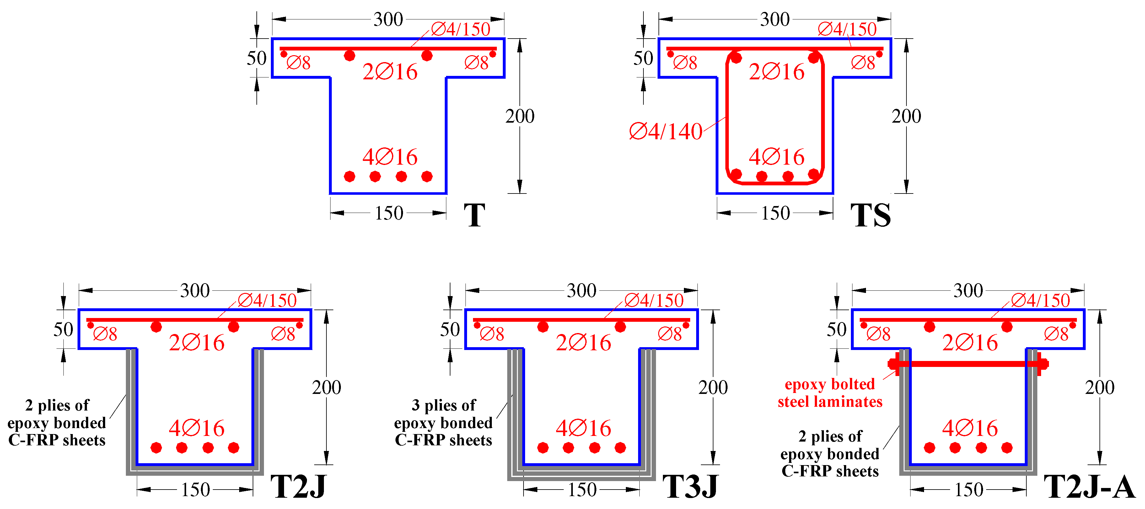
2. Experimental Program
2.1. Materials
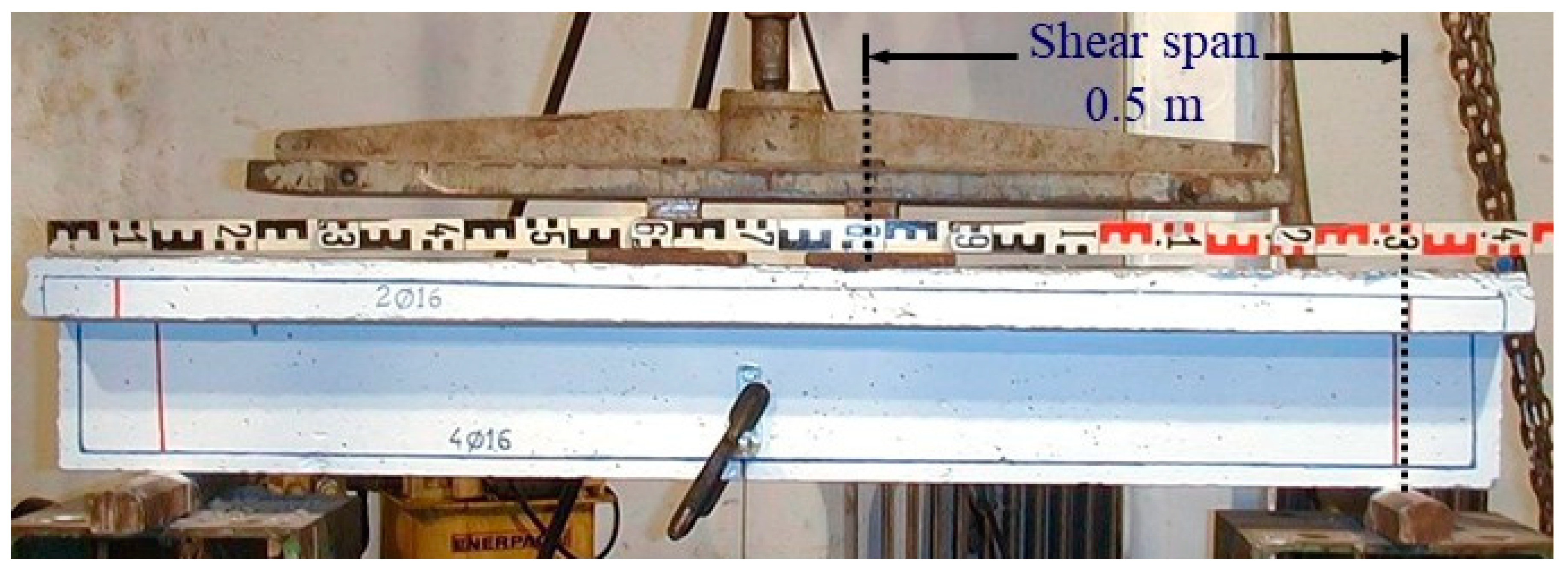
2.2. Test Setup and Instrumentation
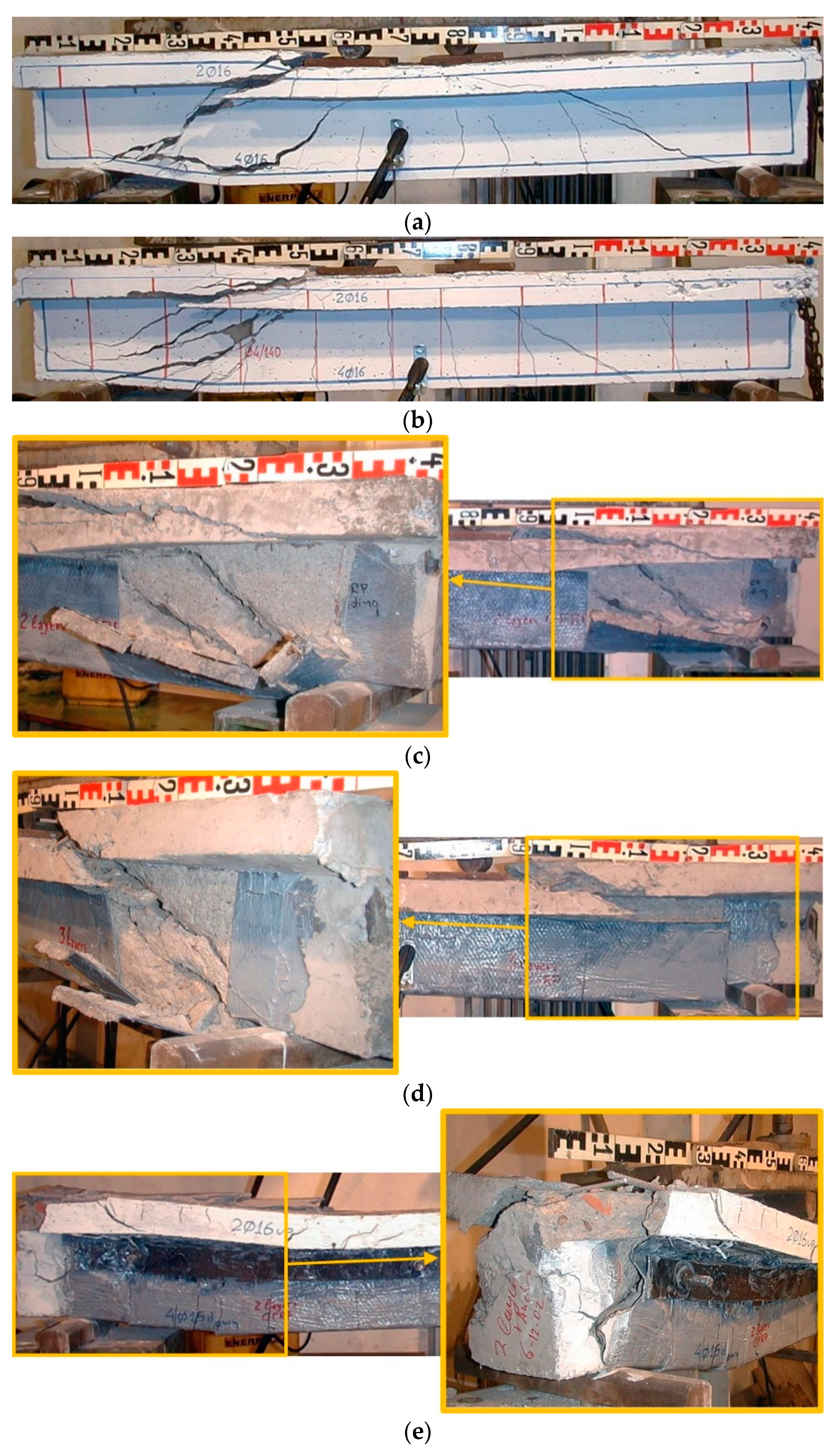
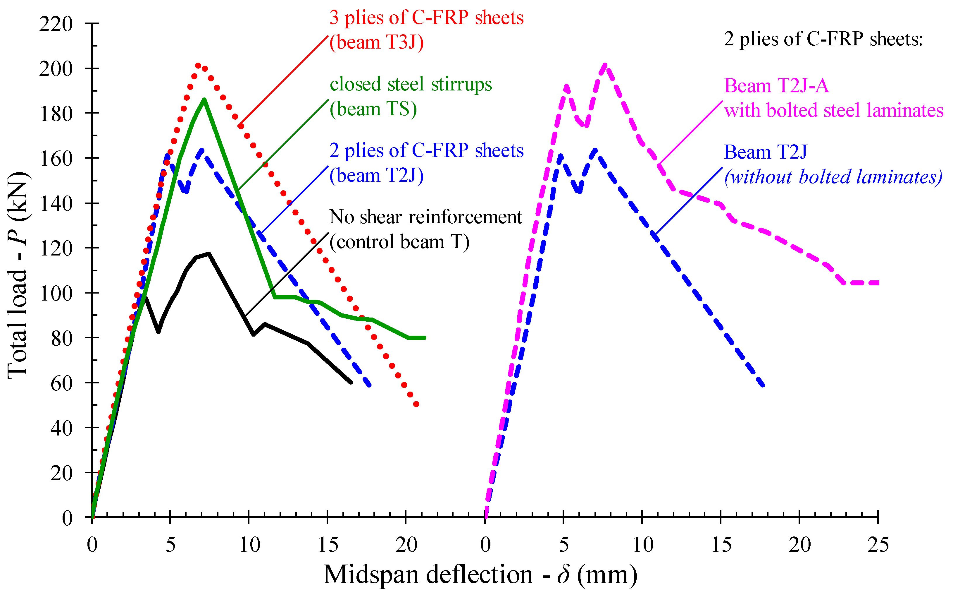
3. Test Results and Commentary
4. Design Provision
4.1. Greek Code of Interventions (KAN.EPE.)
4.2. Eurocode 8 Part 3
4.3. ACI Committee 440
5. Database Results and Discussion
6. Conclusions
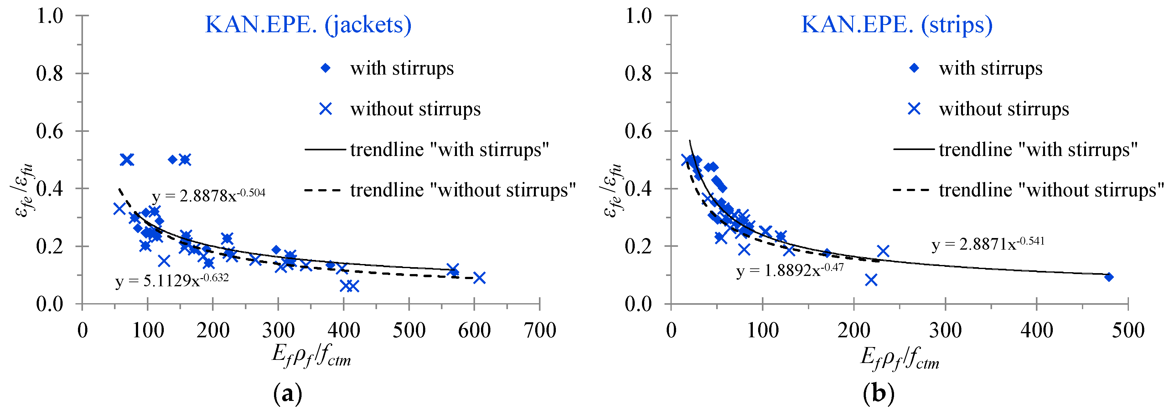
- U-jacketing is an open-form strengthening technique with inadequate anchorage at the edges of the externally applied EB-FRP sheet. The lack of any special anchorage system at these edges significantly affects the shear capacity and the overall behavior of the U-shaped retrofitted RC T-beams. Substantial low potential shear strength and low values of the effective strain of the applied EB-FRP materials are reported due to the occurrence of premature debonding failures.
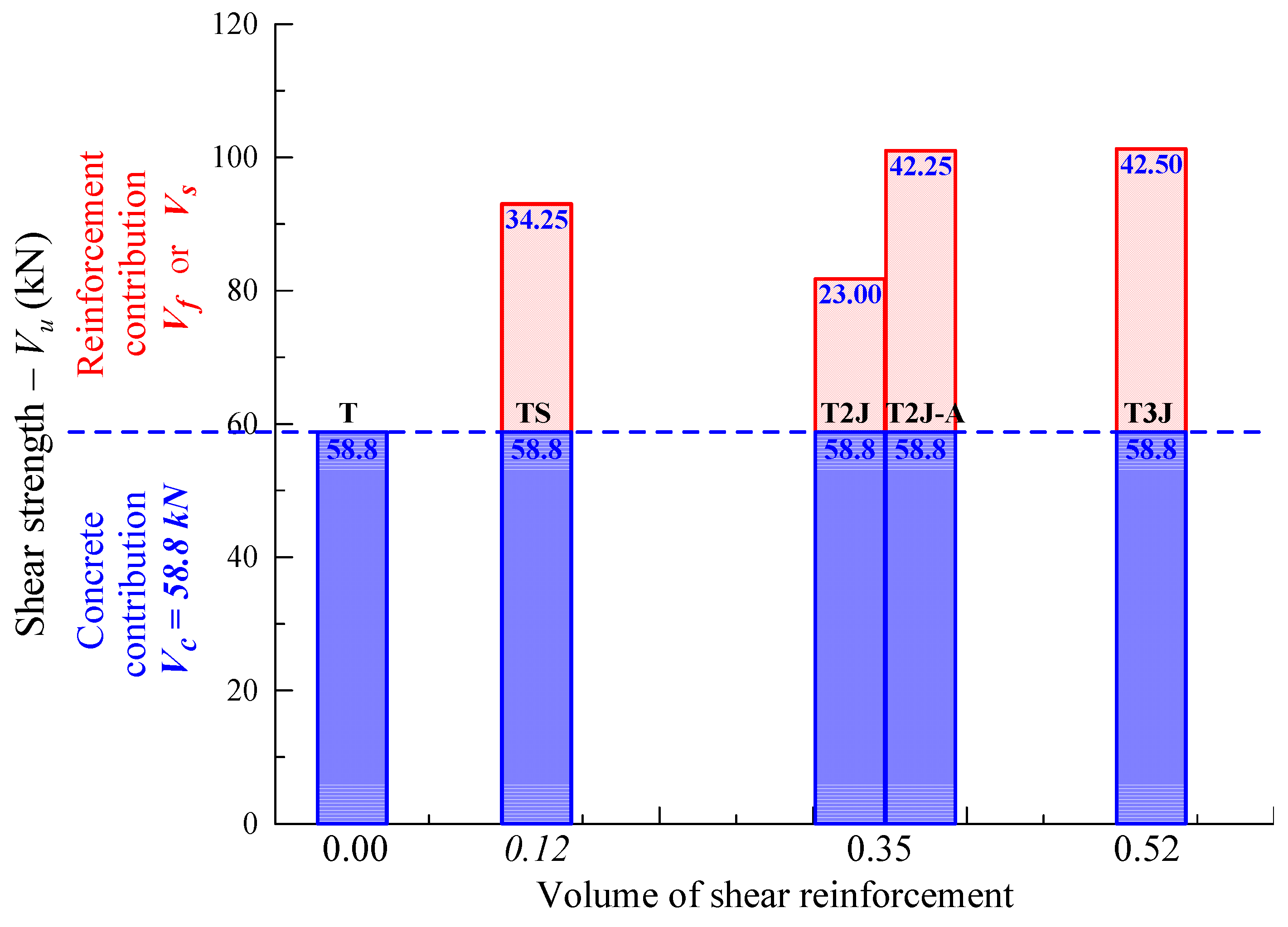
- U-jacketed beams failed due to brittle shear exhibiting severe diagonal cracking of concrete along with the debonding and the peeling-off of the C-FRP sheets from the concrete surface of the beam. However, the examined FRP-strengthened beams demonstrated higher shear strength values than the corresponding non-strengthened beams (control specimens). More specifically, the U-jacketed beams with 2 and 3 plies of C-FRP sheets exhibited 39% and 72% increased shear capacity with respect to the control specimen without transverse reinforcement.
- The failure of the strengthened beam with 2 plies of C-FRP sheets and an additional mechanical anchor of the sheets is also governed by brittle shear although the applied anchorage system prevented the peeling-off of the EB-FRP sheets and the concrete diagonal cracking was not visible since it was hidden behind the C-FRP sheets. Nevertheless, the applied mechanical anchor of the U-shaped C-FRP sheets delayed the debonding resulting in a 72% increase of the shear capacity with respect to the control specimen without transverse reinforcement.
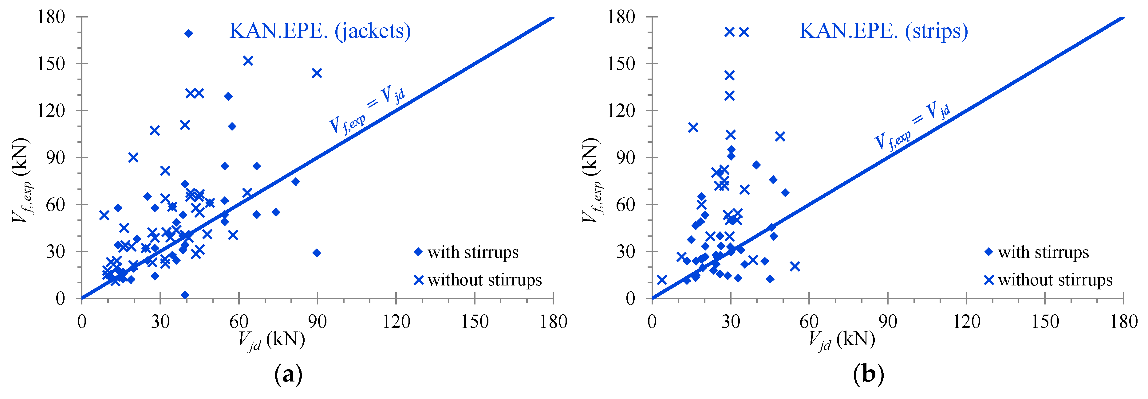
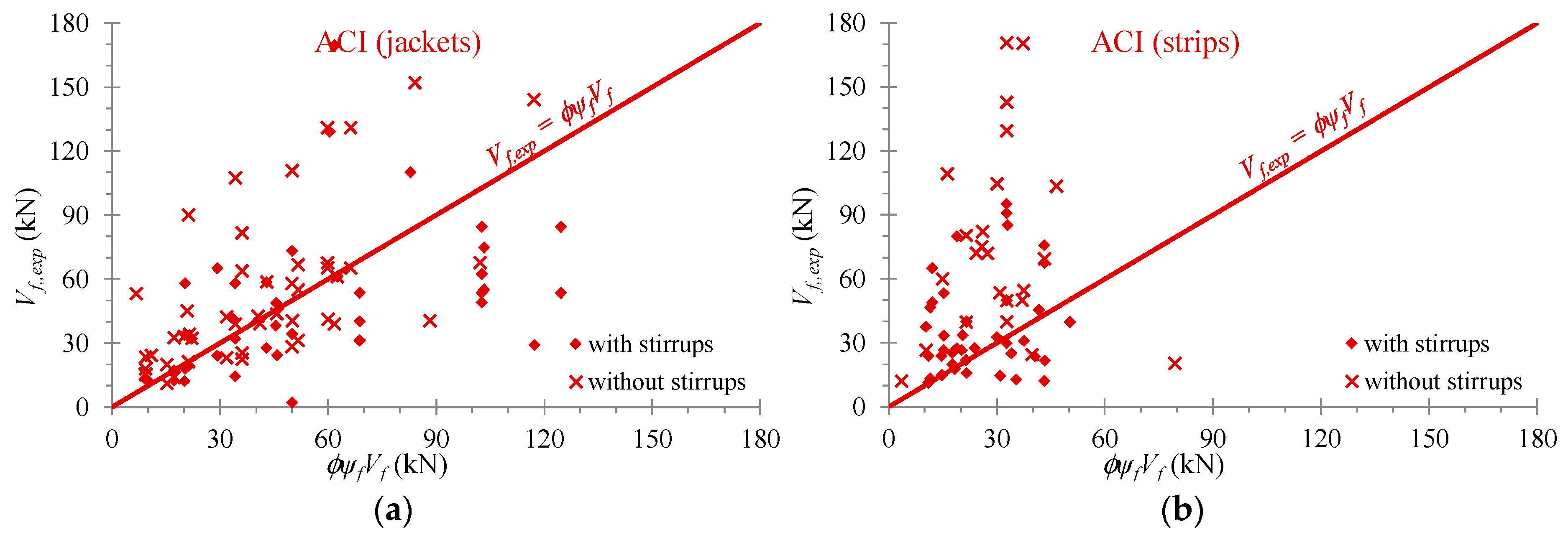
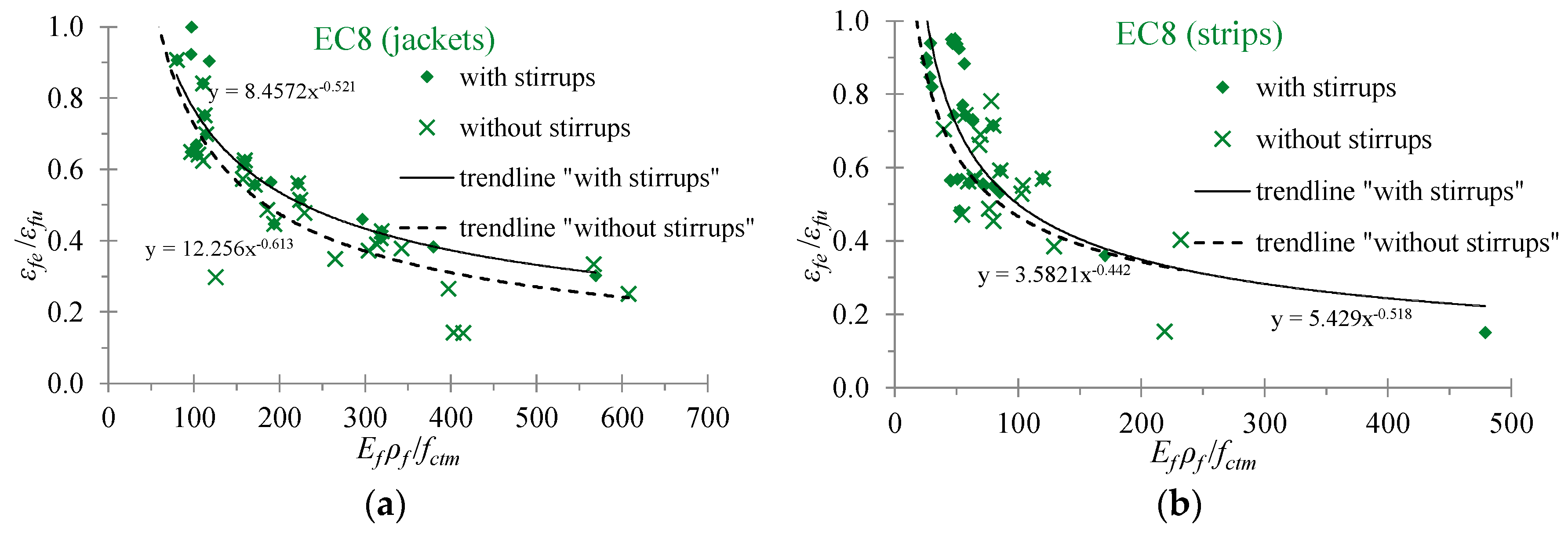
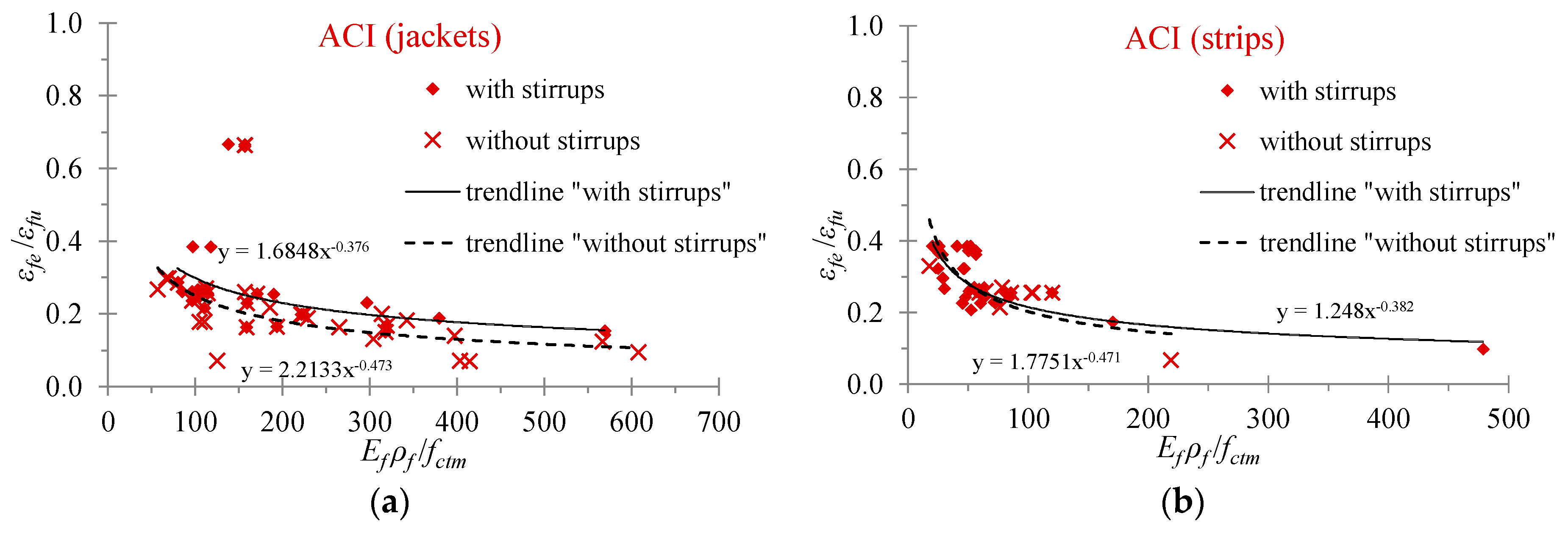
- The provisions and consequently the predictions of the Greek Code of Interventions (KAN.EPE.), Eurocode 8 part 3 and the ACI Committee 440 for shear strengthened RC T-beams using U-shaped EB-FRP jackets or strips vary. Different expressions for the estimation of the effective design strain or/and the corresponding stress are used. Comparisons between 165 test data of T-beams from existing studies and analytical design predictions derived from these provisions indicate that for the majority of the examined beams the Codes provide safe estimations. However, unsafe estimations of all three Codes are observed for certain specimens.
- The present and recent relative studies reveal that although a lot of analytical and experimental investigations on the shear strength of EB-FRP-retrofitted RC beams with rectangular cross-section have been conducted, there is a lack of research concerning the performance of T-beams. Furthermore, ongoing research aims to reduce the scatter in the predictions of the design models. However, additional questions concerning the effectiveness of these estimations also arise from the existing variety of the examined code provisions concerning the shear capacity of EB-FRP strengthened RC T-beams presented herein. The observed discrepancies between test results and analytical predictions and between the existing models are justified, up to a point, by the fact that the shear problem involves the influence of complex interacting phenomena and a number of parameters, such as the properties and the efficiency of the applied EB-FRP materials, the existence of the internal steel reinforcement, the effect of the slab on the shear performance and on the anchorage of the composite sheets among others. Thus, further research efforts are required to understand better the aforementioned issues, to obtain more and reliable experimental results, and to interpret them in order to refine the existing models and code standard provisions.
Author Contributions
Funding
Acknowledgments
Conflicts of Interest
Appendix A

| Ref. | Name | bs/bw/h/hs (mm) | fcm (MPa) | ρsl (%) | ρsw (%) | Ef (GPa) | εfu (%) | ffu (MPa) | FRP 1 | wf/sf | a (deg) | ρf (%) | Vn,exp (kN) | Vf,exp (kN) |
|---|---|---|---|---|---|---|---|---|---|---|---|---|---|---|
| [26] | T6S4-G90 | 400/140/600/150 | 44.1 | 2.8 | 0.10 | 17.7 | 0.60 | 106 | G | 1 | 90 | 2.57 | 297.5 | 109.9 |
| [26] | T6S4-Tri | 400/140/600/150 | 44.1 | 2.8 | 0.10 | 8.1 | 1.53 | 124 | G | 1 | 60 | 3.46 | 316.7 | 129.1 |
| [27] | T4S4-G90 | 400/140/400/150 | 38.0 | 2.1 | 0.10 | 17.7 | 0.60 | 106 | G | 1 | 90 | 2.57 | 205.6 | 48.6 |
| [27] | T4S2-G90 | 400/140/400/150 | 38.3 | 2.1 | 0.20 | 17.7 | 0.60 | 106 | G | 1 | 90 | 2.57 | 225.6 | 24.3 |
| [27] | T4S2-Tri | 400/140/400/150 | 38.4 | 2.1 | 0.20 | 8.1 | 1.53 | 124 | G | 1 | 60 | 3.46 | 242.7 | 41.4 |
| [49] | No.2 | 400/150/300/100 | 44.3 | 5.5 | 0.67 | 230 | 1.51 | 3480 | C | 1 | 90 | 0.15 | 264.0 | 65.0 |
| [49] | No.3 | 400/150/300/100 | 43.8 | 5.5 | 0.67 | 230 | 1.51 | 3480 | C | 1 | 90 | 0.15 | 223.0 | 24.0 |
| [52] | 5 | 300/100/300/50 | 33.4 | 3.6 | 0.75 | 240 | 1.42 | 3400 | C | 1 | 90 | 0.32 | 120.1 | 38.1 |
| [53] | G5.5-1L | 584/122/444.5/89 | 37.9 | 2.7 | 0.83 | 231 | 1.58 | 3650 | C-a | 1 | 90 | 0.24 | 320.3 | 31.2 |
| [53] | G5.5-2L | 584/122/444.5/89 | 37.9 | 2.7 | 0.83 | 231 | 1.58 | 3650 | C-a | 1 | 90 | 0.47 | 342.5 | 53.4 |
| [53] | G8.0-1L | 584/122/444.5/89 | 37.9 | 2.7 | 0.57 | 231 | 1.58 | 3650 | C-a | 1 | 90 | 0.24 | 298.0 | 31.1 |
| [53] | G8.0-2L | 584/122/444.5/89 | 37.9 | 2.7 | 0.57 | 231 | 1.58 | 3650 | C-a | 1 | 90 | 0.47 | 329.2 | 62.3 |
| [53] | G8.0-3L | 584/122/444.5/89 | 37.9 | 2.7 | 0.57 | 231 | 1.58 | 3650 | C-a | 1 | 90 | 0.71 | 351.4 | 84.5 |
| [53] | G16-1L | 584/122/444.5/89 | 37.9 | 2.7 | 0.29 | 231 | 1.58 | 3650 | C-a | 1 | 90 | 0.24 | 275.8 | 40.0 |
| [53] | G16-2L | 584/122/444.5/89 | 37.9 | 2.7 | 0.29 | 231 | 1.58 | 3650 | C-a | 1 | 90 | 0.47 | 320.3 | 84.5 |
| [53] | G24-1L | 584/122/444.5/89 | 37.9 | 2.7 | 0.19 | 231 | 1.58 | 3650 | C-a | 1 | 90 | 0.24 | 258.0 | 53.4 |
| [53] | G24-2L | 584/122/444.5/89 | 37.9 | 2.7 | 0.19 | 231 | 1.58 | 3650 | C-a | 1 | 90 | 0.47 | 253.5 | 48.9 |
| [53] | G24-3L | 584/122/444.5/89 | 37.9 | 2.7 | 0.19 | 231 | 1.58 | 3650 | C-a | 1 | 90 | 0.71 | 258.0 | 53.4 |
| [55] | DB-S1-1L | 270/95/220/55 | 25.5 | 3.6 | 0.38 | 231 | 1.58 | 3650 | C-a | 1 | 90 | 0.14 | 162.5 | 12.7 |
| [55] | DB-S1-2L | 270/95/220/55 | 25.5 | 3.6 | 0.38 | 231 | 1.58 | 3650 | C-a | 1 | 90 | 0.28 | 166.8 | 17.0 |
| [55] | SB-S1-1L | 270/95/220/55 | 25.5 | 3.6 | 0.38 | 231 | 1.58 | 3650 | C-a | 1 | 90 | 0.14 | 95.7 | 2.8 |
| [55] | SB-S1-2L | 270/95/220/55 | 25.5 | 3.6 | 0.38 | 231 | 1.58 | 3650 | C-a | 1 | 90 | 0.28 | 105.1 | 12.2 |
| [56] | DB_S1_1L | 508/152/406/102 | 25.0 | 3.8 | 0.38 | 231 | 1.40 | 3650 | C | 1 | 90 | 0.14 | 355.5 | 32.0 |
| [56] | DB_S1_2L | 508/152/406/102 | 25.0 | 3.8 | 0.38 | 231 | 1.40 | 3650 | C | 1 | 90 | 0.28 | 357.7 | 34.2 |
| [56] | DB_S2_1L | 508/152/406/102 | 25.0 | 3.8 | 0.75 | 231 | 1.40 | 3650 | C | 1 | 90 | 0.14 | 389.7 | 58.0 |
| [56] | DB_S2_2L | 508/152/406/102 | 25.0 | 3.8 | 0.75 | 231 | 1.40 | 3650 | C | 1 | 90 | 0.28 | 404.8 | 73.1 |
| [56] | SB_S1_05L | 508/152/406/102 | 25.0 | 3.8 | 0.38 | 231 | 1.40 | 3650 | C | 1 | 90 | 0.07 | 282.0 | 19.2 |
| [56] | SB_S1_1L | 508/152/406/102 | 25.0 | 3.8 | 0.38 | 231 | 1.40 | 3650 | C | 1 | 90 | 0.14 | 255.0 | 0.0 |
| [56] | SB_S1_2L | 508/152/406/102 | 25.0 | 3.8 | 0.38 | 231 | 1.40 | 3650 | C | 1 | 90 | 0.28 | 267.2 | 4.4 |
| [56] | SB_S2_1L | 508/152/406/102 | 25.0 | 3.8 | 0.75 | 231 | 1.40 | 3650 | C | 1 | 90 | 0.14 | 309.4 | 14.3 |
| [56] | SB_S2_2L | 508/152/406/102 | 25.0 | 3.8 | 0.75 | 231 | 1.40 | 3650 | C | 1 | 90 | 0.28 | 297.2 | 2.1 |
| [60] | S1-0.33R | 508/150/406/102 | 31.0 | 3.8 | 0.38 | 230 | 1.50 | 3450 | C | 1 | 90 | 0.15 | 378.3 | 27.7 |
| [63] | WT-SH-100 | 508/152/406/102 | 37.0 | 3.8 | 0.38 | 230 | 1.50 | 3450 | C | 1 | 90 | 0.21 | 250.6 | 169.4 |
| [65] | TB2 | 300/130/275/75 | 34.0 | 4.4 | 0.17 | 119 | 1.60 | 1400 | C | 1 | 90 | 0.23 | 140.0 | 18.0 |
| [65] | TB3 | 300/130/275/75 | 34.0 | 4.4 | 0.17 | 119 | 1.60 | 1400 | C-a | 1 | 90 | 0.23 | 180.0 | 58.0 |
| [65] | TB4 | 300/130/275/75 | 34.0 | 4.4 | 0.17 | 119 | 1.60 | 1400 | C-a | 1 | 90 | 0.23 | 156.0 | 34.0 |
| [67] | S.S1.1L | 270/95/220/55 | 30.0 | 3.6 | 0.37 | 231 | 1.40 | 3650 | C | 1 | 90 | 0.14 | 98.0 | 3.0 |
| [67] | M.S1.1L | 508/152/406/102 | 30.0 | 3.8 | 0.38 | 231 | 1.40 | 3650 | C | 1 | 90 | 0.14 | 260.0 | 0.0 |
| [67] | L.S1.1L | 745/275/605/150 | 30.0 | 3.6 | 0.41 | 231 | 1.40 | 3650 | C | 1 | 90 | 0.12 | 590.0 | 0.0 |
| [67] | S.S1.2L | 270/95/220/55 | 30.0 | 3.6 | 0.37 | 231 | 1.40 | 3650 | C | 1 | 90 | 0.28 | 107.0 | 12.0 |
| [67] | M.S1.2L | 508/152/406/102 | 30.0 | 3.8 | 0.38 | 231 | 1.40 | 3650 | C | 1 | 90 | 0.28 | 272.0 | 4.0 |
| [67] | L.S1.2L | 745/275/605/150 | 30.0 | 3.6 | 0.41 | 231 | 1.40 | 3650 | C | 1 | 90 | 0.24 | 629.0 | 29.0 |
| [70] | H3A | 600/200/550/150 | 44.7 | 2.1 | 0.12 | 263 | 1.04 | 2739 | C-a | 1 | 90 | 0.17 | 382.2 | 55.1 |
| [70] | H3B | 600/200/550/150 | 49.6 | 2.1 | 0.12 | 263 | 1.04 | 2739 | C-a | 1 | 90 | 0.17 | 408.6 | 74.6 |
| Ref. | Name | bs/bw/h/hs (mm) | fcm (MPa) | ρsl (%) | ρsw (%) | Ef (GPa) | εfu (%) | ffu (MPa) | FRP 1 | wf/sf | a (deg) | ρf (%) | Vn,exp (kN) | Vf,exp (kN) |
|---|---|---|---|---|---|---|---|---|---|---|---|---|---|---|
| p.s. | T2J | 300/150/200/50 | 35.2 | 3.1 | 0.00 | 230 | 1.50 | 3500 | C | 1 | 90 | 0.35 | 81.9 | 23.1 |
| p.s. | T3J | 300/150/200/50 | 35.2 | 3.1 | 0.00 | 230 | 1.50 | 3500 | C | 1 | 90 | 0.52 | 101.3 | 42.5 |
| p.s. | T2J-A | 300/150/200/50 | 35.2 | 3.1 | 0.00 | 230 | 1.50 | 3500 | C-a | 1 | 90 | 0.35 | 101.0 | 42.2 |
| [25] | BT2 | 380/150/405/100 | 35.0 | 2.3 | 0.00 | 228 | 1.66 | 3790 | C | 1 | 90 | 0.22 | 155.0 | 65.0 |
| [25] | BT3 | 380/150/405/100 | 35.0 | 2.3 | 0.00 | 228 | 1.66 | 3790 | C-a | 1 | 90 | 0.22 | 157.5 | 67.5 |
| [25] | BT6 | 380/150/405/100 | 35.0 | 2.3 | 0.00 | 228 | 1.66 | 3790 | C-a | 1 | 90 | 0.22 | 221.0 | 131.0 |
| [27] | T4NS-G90 | 400/140/400/150 | 38.2 | 2.1 | 0.00 | 17.7 | 0.60 | 106 | G | 1 | 90 | 2.57 | 159.0 | 43.6 |
| [48] | A1 | 140/64/191/64 | 59.6 | 2.1 | 0.00 | 13.2 | 2.25 | 296 | A | 1 | 90 | 3.28 | 38.7 | 19.7 |
| [48] | A2 | 140/64/191/64 | 55.0 | 2.1 | 0.00 | 13.2 | 2.25 | 296 | A | 1 | 90 | 3.28 | 30.0 | 11.0 |
| [48] | E1 | 140/64/191/64 | 56.8 | 2.1 | 0.00 | 12.8 | 1.34 | 172 | G | 1 | 90 | 2.08 | 36.7 | 17.7 |
| [48] | E2 | 140/64/191/64 | 53.3 | 2.1 | 0.00 | 12.8 | 1.34 | 172 | G | 1 | 90 | 2.08 | 34.0 | 15.0 |
| [50] | C-BT2 | 380/150/405/100 | 43.3 | 2.3 | 0.00 | 228 | 1.54 | 3790 | C | 1 | 90 | 0.22 | 155.0 | 65.0 |
| [50] | C-BT3 | 380/150/405/100 | 43.3 | 2.3 | 0.00 | 228 | 1.54 | 3790 | C | 1 | 90 | 0.44 | 157.5 | 67.5 |
| [50] | C-BT6 | 380/150/405/100 | 43.3 | 2.3 | 0.00 | 228 | 1.54 | 3790 | C | 1 | 90 | 0.22 | 221.0 | 131.0 |
| [51] | JS2A | 660/152/381/76 | 20.6 | 0.5 | 0.00 | 228 | 1.66 | 3790 | C | 1 | 90 | 0.22 | 237.1 | 25.2 |
| [51] | JS2B | 660/152/381/76 | 20.6 | 0.5 | 0.00 | 228 | 1.66 | 3790 | C | 1 | 90 | 0.22 | 234.2 | 22.3 |
| [51] | JS3A | 660/152/381/76 | 20.6 | 0.5 | 0.00 | 228 | 1.66 | 3790 | C | 1 | 90 | 0.22 | 293.4 | 81.5 |
| [51] | JS3B | 660/152/381/76 | 20.6 | 0.5 | 0.00 | 228 | 1.66 | 3790 | C | 1 | 90 | 0.22 | 275.7 | 63.8 |
| [51] | JS4A | 660/152/381/76 | 20.6 | 0.5 | 0.00 | 228 | 1.66 | 3790 | C | 1 | 90 | 0.43 | 243.1 | 31.2 |
| [51] | JS4B | 660/152/381/76 | 20.6 | 0.5 | 0.00 | 228 | 1.66 | 3790 | C | 1 | 90 | 0.43 | 207.5 | 0.0 |
| [51] | JS5A | 660/152/381/76 | 20.6 | 0.5 | 0.00 | 228 | 1.66 | 3790 | C | 1 | 90 | 0.43 | 278.6 | 66.7 |
| [51] | JS5B | 660/152/381/76 | 20.6 | 0.5 | 0.00 | 228 | 1.66 | 3790 | C | 1 | 90 | 0.43 | 266.8 | 54.9 |
| [51] | JS6A | 660/152/381/76 | 20.6 | 0.5 | 0.00 | 117 | 1.30 | 1517 | A | 1 | 90 | 0.79 | 269.7 | 57.8 |
| [51] | JS6B | 660/152/381/76 | 20.6 | 0.5 | 0.00 | 117 | 1.30 | 1517 | A | 1 | 90 | 0.79 | 240.1 | 28.2 |
| [55] | DB-S0-1L | 270/95/220/55 | 25.5 | 3.6 | 0.00 | 231 | 1.58 | 3650 | C-a | 1 | 90 | 0.14 | 162.2 | 15.4 |
| [55] | DB-S0-2L | 270/95/220/55 | 25.5 | 3.6 | 0.00 | 231 | 1.58 | 3650 | C-a | 1 | 90 | 0.28 | 160.6 | 13.8 |
| [55] | SB-S0-1L | 270/95/220/55 | 25.5 | 3.6 | 0.00 | 231 | 1.58 | 3650 | C-a | 1 | 90 | 0.14 | 59.3 | 23.2 |
| [55] | SB-S0-2L | 270/95/220/55 | 25.5 | 3.6 | 0.00 | 231 | 1.58 | 3650 | C-a | 1 | 90 | 0.28 | 68.5 | 32.4 |
| [56] | DB_S0_05L | 508/152/406/102 | 25.0 | 3.8 | 0.00 | 231 | 1.40 | 3650 | C | 1 | 90 | 0.07 | 268.2 | 90.0 |
| [56] | DB_S0_1L | 508/152/406/102 | 25.0 | 3.8 | 0.00 | 231 | 1.40 | 3650 | C | 1 | 90 | 0.14 | 285.5 | 107.3 |
| [56] | DB_S0_2L | 508/152/406/102 | 25.0 | 3.8 | 0.00 | 231 | 1.40 | 3650 | C | 1 | 90 | 0.28 | 289.0 | 110.8 |
| [56] | SB_S0_05L | 508/152/406/102 | 25.0 | 3.8 | 0.00 | 231 | 1.40 | 3650 | C | 1 | 90 | 0.07 | 102.4 | 21.2 |
| [56] | SB_S0_1L | 508/152/406/102 | 25.0 | 3.8 | 0.00 | 231 | 1.40 | 3650 | C | 1 | 90 | 0.14 | 120.0 | 38.8 |
| [56] | SB_S0_2L | 508/152/406/102 | 25.0 | 3.8 | 0.00 | 231 | 1.40 | 3650 | C | 1 | 90 | 0.28 | 121.7 | 40.5 |
| [60] | S0-0.17R2 | 508/150/406/102 | 31.0 | 3.8 | 0.00 | 230 | 1.50 | 3450 | C | 1 | 90 | 0.07 | 154.7 | 32.0 |
| [60] | S0-0.33R | 508/150/406/102 | 31.0 | 3.8 | 0.00 | 230 | 1.50 | 3450 | C | 1 | 90 | 0.15 | 181.2 | 58.5 |
| [60] | S0-0.66R | 508/150/406/102 | 31.0 | 3.8 | 0.00 | 230 | 1.50 | 3450 | C | 1 | 90 | 0.29 | 183.8 | 61.1 |
| [62] | SB1 | 350/150/175/50 | 27.9 | 3.4 | 0.00 | 68.3 | 2.53 | 172.79 | G | 1 | 90 | 1.30 | 115.0 | 34.0 |
| [62] | SB8 | 350/150/175/50 | 27.1 | 3.4 | 0.00 | 68.3 | 2.53 | 172.79 | G-a | 1 | 90 | 1.30 | 126.0 | 45.0 |
| [62] | SB9 | 350/150/175/50 | 26.1 | 3.4 | 0.00 | 77.9 | 2.68 | 209.09 | G-a | 1 | 90 | 0.33 | 134.0 | 53.0 |
| [63] | NT-SH-100 | 508/152/406/102 | 37.0 | 3.8 | 0.00 | 230 | 1.50 | 3450 | C | 1 | 90 | 0.21 | 120.0 | 38.8 |
| [63] | NT-SH-200 | 508/152/406/102 | 37.0 | 3.8 | 0.00 | 230 | 1.50 | 3450 | C | 1 | 90 | 0.42 | 121.7 | 40.5 |
| [67] | S.S0.1L | 270/95/220/55 | 30.0 | 3.6 | 0.00 | 231 | 1.40 | 3650 | C | 1 | 90 | 0.14 | 62.0 | 24.0 |
| [67] | M.S0.1L | 508/152/406/102 | 30.0 | 3.8 | 0.00 | 231 | 1.40 | 3650 | C | 1 | 90 | 0.14 | 125.0 | 39.0 |
| [67] | L.S0.1L | 745/275/605/150 | 30.0 | 3.6 | 0.00 | 231 | 1.40 | 3650 | C | 1 | 90 | 0.12 | 334.0 | 152.0 |
| [67] | S.S0.2L | 270/95/220/55 | 30.0 | 3.6 | 0.00 | 231 | 1.40 | 3650 | C | 1 | 90 | 0.28 | 71.0 | 33.0 |
| [67] | M.S0.2L | 508/152/406/102 | 30.0 | 3.8 | 0.00 | 231 | 1.40 | 3650 | C | 1 | 90 | 0.28 | 127.0 | 41.0 |
| [67] | L.S0.2L | 745/275/605/150 | 30.0 | 3.6 | 0.00 | 231 | 1.40 | 3650 | C | 1 | 90 | 0.24 | 326.0 | 144.0 |
| Ref. | Name | bs/bw/h/hs (mm) | fcm (MPa) | ρsl (%) | ρsw (%) | Ef (GPa) | εfu (%) | ffu (MPa) | FRP 1 | wf/sf | a (deg) | ρf (%) | Vn,exp (kN) | Vf,exp (kN) |
|---|---|---|---|---|---|---|---|---|---|---|---|---|---|---|
| [26] | T6S4-C90 | 400/140/600/150 | 44.1 | 2.8 | 0.10 | 230 | 1.48 | 3400 | C | 0.50 | 90 | 0.08 | 272.8 | 85.2 |
| [26] | T6S2-C90 | 400/140/600/150 | 44.1 | 2.8 | 0.20 | 230 | 1.48 | 3400 | C | 0.50 | 90 | 0.08 | 309.8 | 0.0 |
| [27] | T4S2-C45 | 400/140/400/150 | 37.4 | 2.2 | 0.20 | 230 | 1.48 | 3400 | C | 0.35 | 45 | 0.08 | 219.1 | 17.8 |
| [52] | 6 | 300/100/300/50 | 33.4 | 3.6 | 0.75 | 155 | 1.55 | 2400 | G | 0.33 | 90 | 0.80 | 107.2 | 25.1 |
| [54] | 2S_4M(1) | 450/180/400/100 | 38.1 | 2.8 | 0.11 | 240 | 1.50 | 3600 | C | 0.33 | 90 | 0.07 | 186.7 | 4.4 |
| [54] | 2S_7M(1) | 450/180/400/100 | 38.1 | 2.8 | 0.11 | 240 | 1.50 | 3600 | C | 0.53 | 90 | 0.10 | 195.1 | 12.8 |
| [54] | 2S_7M(2) | 450/180/400/100 | 38.1 | 2.8 | 0.11 | 240 | 1.50 | 3600 | C | 0.53 | 90 | 0.21 | 222.1 | 39.8 |
| [54] | 4S_4M(1) | 450/180/400/100 | 41.0 | 2.8 | 0.18 | 240 | 1.50 | 3600 | C | 0.33 | 90 | 0.07 | 250.4 | 27.6 |
| [54] | 4S_7M(1) | 450/180/400/100 | 41.0 | 2.8 | 0.18 | 240 | 1.50 | 3600 | C | 0.53 | 90 | 0.10 | 253.8 | 31.0 |
| [57] | TT1-1 | 400/120/340/100 | 38.0 | 1.7 | 0.79 | 230 | 1.65 | 3800 | C | 0.53 | 90 | 0.08 | 120.6 | 33.3 |
| [57] | TT1-1I | 400/120/340/100 | 38.0 | 1.7 | 0.79 | 230 | 1.65 | 3800 | C | 0.53 | 90 | 0.08 | 140.5 | 53.2 |
| [57] | TT1-2 | 400/120/340/100 | 38.0 | 1.7 | 0.79 | 230 | 1.65 | 3800 | C | 0.40 | 90 | 0.06 | 133.9 | 46.6 |
| [57] | TS1-1 | 400/120/340/100 | 38.0 | 1.7 | 0.40 | 230 | 1.65 | 3800 | C | 0.53 | 90 | 0.08 | 94.0 | 26.6 |
| [57] | TS1-1I | 400/120/340/100 | 38.0 | 1.7 | 0.40 | 230 | 1.65 | 3800 | C | 0.53 | 90 | 0.08 | 60.7 | 0.0 |
| [57] | TS1-2 | 400/120/340/100 | 38.0 | 1.7 | 0.40 | 230 | 1.65 | 3800 | C | 0.40 | 90 | 0.06 | 80.7 | 13.3 |
| [58] | 2 | 360/120/360/75 | 33.2 | 2.4 | 0.16 | 231 | 1.70 | 4100 | C | 0.40 | 90 | 0.08 | 50.7 | 19.7 |
| [58] | 3 | 360/120/360/75 | 32.9 | 2.4 | 0.16 | 231 | 1.70 | 4100 | C | 0.33 | 90 | 0.07 | 45.8 | 14.8 |
| [58] | 4 | 360/120/360/75 | 32.8 | 2.4 | 0.16 | 231 | 1.70 | 4100 | C | 0.25 | 90 | 0.05 | 42.3 | 11.3 |
| [58] | 5 | 360/120/360/75 | 32.8 | 2.4 | 0.16 | 231 | 1.70 | 4100 | C | 0.40 | 90 | 0.08 | 56.3 | 25.3 |
| [58] | 6 | 360/120/360/75 | 33.0 | 2.4 | 0.16 | 231 | 1.70 | 4100 | C | 0.33 | 90 | 0.07 | 54.9 | 23.9 |
| [58] | 7 | 360/120/360/75 | 32.9 | 2.4 | 0.16 | 231 | 1.70 | 4100 | C | 0.25 | 90 | 0.05 | 54.9 | 23.9 |
| [59] | VTC1 | 400/120/300/80 | 68.0 | 2.0 | 0.11 | 221 | 1.24 | 2728 | C | 0.33 | 90 | 0.06 | 110.0 | 37.5 |
| [59] | VTC3 | 400/120/300/80 | 68.5 | 2.0 | 0.11 | 219 | 1.24 | 2730 | C | 0.40 | 90 | 0.11 | 100.0 | 27.5 |
| [59] | VTC4 | 400/120/300/80 | 67.6 | 2.0 | 0.11 | 219 | 1.24 | 2730 | C | 0.40 | 90 | 0.11 | 152.5 | 80.0 |
| [59] | VTC5 | 400/120/300/80 | 68.0 | 2.0 | 0.11 | 221 | 1.50 | 2915 | C | 0.29 | 90 | 0.07 | 121.5 | 49.0 |
| [59] | VTC6 | 400/120/300/80 | 65.6 | 2.0 | 0.11 | 221 | 1.35 | 2915 | C | 0.29 | 90 | 0.07 | 137.5 | 65.0 |
| [60] | S1-0.17R1 | 508/150/406/102 | 31.0 | 3.8 | 0.38 | 230 | 1.50 | 3450 | C | 0.50 | 90 | 0.07 | 365.9 | 15.3 |
| [60] | S1-0.17R2 | 508/150/406/102 | 31.0 | 3.8 | 0.38 | 230 | 1.50 | 3450 | C | 0.50 | 90 | 0.07 | 372.5 | 21.9 |
| [60] | S1-0.23R | 508/150/406/102 | 31.0 | 3.8 | 0.38 | 230 | 1.50 | 3450 | C | 0.70 | 90 | 0.10 | 383.4 | 32.8 |
| [63] | WT-ST-50 | 508/152/406/102 | 37.0 | 3.8 | 0.38 | 230 | 1.50 | 3450 | C | 0.50 | 90 | 0.11 | 246.7 | 14.5 |
| [63] | WT-ST-70 | 508/152/406/102 | 37.0 | 3.8 | 0.38 | 230 | 1.50 | 3450 | C | 0.70 | 90 | 0.15 | 253.9 | 21.7 |
| [64] | S8-U | 500/200/400/100 | 46.1 | 3.8 | 0.25 | 226 | 1.93 | 4361 | C | 0.50 | 90 | 0.08 | 300.8 | 29.7 |
| [64] | S8-UFA1 | 500/200/400/100 | 46.1 | 3.8 | 0.25 | 226 | 1.93 | 4361 | C-a | 0.50 | 90 | 0.08 | 321.0 | 49.9 |
| [64] | S8-UFA2 | 500/200/400/100 | 46.1 | 3.8 | 0.25 | 226 | 1.93 | 4361 | C-a | 0.50 | 90 | 0.08 | 366.3 | 95.1 |
| [64] | S8-UEA1 | 500/200/400/100 | 46.1 | 3.8 | 0.25 | 226 | 1.93 | 4361 | C-a | 0.50 | 90 | 0.08 | 361.9 | 90.8 |
| [70] | M1-a | 600/200/550/150 | 42.8 | 1.6 | 0.12 | 263 | 1.04 | 2739 | C | 0.21 | 90 | 0.04 | 349.4 | 40.0 |
| [70] | M1-b | 600/200/550/150 | 42.8 | 1.6 | 0.12 | 263 | 1.04 | 2739 | C | 0.21 | 90 | 0.04 | 324.7 | 15.7 |
| [70] | M2-a | 600/200/550/150 | 39.8 | 1.6 | 0.12 | 263 | 1.04 | 2739 | C | 0.42 | 90 | 0.07 | 284.9 | 0.0 |
| [70] | M2-b | 600/200/550/150 | 39.8 | 1.6 | 0.12 | 263 | 1.04 | 2739 | C | 0.42 | 90 | 0.07 | 259.1 | 0.0 |
| [70] | M1A | 600/200/550/150 | 39.0 | 1.6 | 0.12 | 263 | 1.04 | 2739 | C-a | 0.21 | 90 | 0.04 | 335.8 | 33.5 |
| [70] | M1B | 600/200/550/150 | 38.5 | 1.6 | 0.12 | 263 | 1.04 | 2739 | C-a | 0.21 | 90 | 0.04 | 328.1 | 26.5 |
| [70] | M2A | 600/200/550/150 | 39.0 | 1.6 | 0.12 | 263 | 1.04 | 2739 | C-a | 0.42 | 90 | 0.07 | 348.0 | 45.4 |
| [70] | M2B | 600/200/550/150 | 38.5 | 1.6 | 0.12 | 263 | 1.04 | 2739 | C-a | 0.42 | 90 | 0.07 | 325.0 | 23.6 |
| [70] | H1-a | 600/200/550/150 | 44.4 | 2.1 | 0.12 | 263 | 1.04 | 2739 | C | 0.21 | 90 | 0.04 | 333.8 | 8.1 |
| [70] | H1-b | 600/200/550/150 | 49.7 | 2.1 | 0.12 | 263 | 1.04 | 2739 | C | 0.21 | 90 | 0.04 | 335.8 | 1.1 |
| [70] | H2-a | 600/200/550/150 | 44.4 | 2.1 | 0.12 | 263 | 1.04 | 2739 | C | 0.42 | 90 | 0.07 | 338.1 | 12.2 |
| [70] | H2-b | 600/200/550/150 | 49.7 | 2.1 | 0.12 | 263 | 1.04 | 2739 | C | 0.42 | 90 | 0.07 | 340.4 | 6.9 |
| [70] | H2A | 600/200/550/150 | 44.7 | 2.1 | 0.12 | 263 | 1.04 | 2739 | C-a | 0.42 | 90 | 0.07 | 402.9 | 75.8 |
| [70] | H2B | 600/200/550/150 | 49.6 | 2.1 | 0.12 | 263 | 1.04 | 2739 | C-a | 0.42 | 90 | 0.07 | 401.6 | 67.6 |
| Ref. | Name | bs/bw/h/hs (mm) | fcm (MPa) | ρsl (%) | ρsw (%) | Ef (GPa) | εfu (%) | ffu (MPa) | FRP 1 | wf/sf | a (deg) | ρf (%) | Vn,exp (kN) | Vf,exp (kN) |
|---|---|---|---|---|---|---|---|---|---|---|---|---|---|---|
| [25] | BT4 | 380/150/405/100 | 35.0 | 2.3 | 0.00 | 228 | 1.66 | 3790 | C | 0.40 | 90 | 0.09 | 162.0 | 72.0 |
| [26] | T6NS-C45 | 400/140/600/150 | 44.1 | 2.8 | 0.00 | 230 | 1.48 | 3400 | C | 0.50 | 45 | 0.11 | 213.6 | 103.5 |
| [50] | C-BT4 | 380/150/405/100 | 43.3 | 2.3 | 0.00 | 228 | 1.54 | 3790 | C | 0.40 | 90 | 0.09 | 162.0 | 72.0 |
| [60] | S0-0.12R | 508/150/406/102 | 31.0 | 3.8 | 0.00 | 230 | 1.50 | 3450 | C | 0.35 | 90 | 0.05 | 182.6 | 59.9 |
| [60] | S0-0.17R1 | 508/150/406/102 | 31.0 | 3.8 | 0.00 | 230 | 1.50 | 3450 | C | 0.50 | 90 | 0.07 | 203.1 | 80.4 |
| [60] | S0-0.17R2 | 508/150/406/102 | 31.0 | 3.8 | 0.00 | 230 | 1.50 | 3450 | C | 0.61 | 90 | 0.09 | 204.9 | 82.2 |
| [60] | S0-0.20R1 | 508/150/406/102 | 31.0 | 3.8 | 0.00 | 230 | 1.50 | 3450 | C | 0.60 | 90 | 0.09 | 197.9 | 75.2 |
| [60] | S0-0.20R2 | 508/150/406/102 | 31.0 | 3.8 | 0.00 | 230 | 1.50 | 3450 | C | 0.70 | 90 | 0.10 | 227.3 | 104.6 |
| [61] | S0-1L-ST-U-90 | 250/100/260/60 | 40.0 | 2.8 | 0.00 | 13.2 | 1.21 | 160 | G | 0.50 | 90 | 0.36 | 62.0 | 12.0 |
| [62] | SB3 | 350/150/175/50 | 26.3 | 3.4 | 0.00 | 68.3 | 2.53 | 172.79 | G | 0.50 | 90 | 0.67 | 107.5 | 26.5 |
| [63] | NT-ST-35 | 508/152/406/102 | 37.0 | 3.8 | 0.00 | 230 | 1.50 | 3450 | C | 0.35 | 90 | 0.07 | 120.9 | 39.7 |
| [63] | NT-ST-50 | 508/152/406/102 | 37.0 | 3.8 | 0.00 | 230 | 1.50 | 3450 | C | 0.50 | 90 | 0.11 | 134.5 | 53.3 |
| [63] | NT-ST-60 | 508/152/406/102 | 37.0 | 3.8 | 0.00 | 230 | 1.50 | 3450 | C | 0.60 | 90 | 0.13 | 131.1 | 49.9 |
| [63] | NT-ST-61 | 508/152/406/102 | 37.0 | 3.8 | 0.00 | 230 | 1.50 | 3450 | C | 0.61 | 90 | 0.13 | 135.7 | 54.5 |
| [63] | NT-ST-70 | 508/152/406/102 | 37.0 | 3.8 | 0.00 | 230 | 1.50 | 3450 | C | 0.70 | 90 | 0.15 | 150.6 | 69.4 |
| [64] | S0-U | 500/200/400/100 | 43.0 | 3.8 | 0.00 | 226 | 1.93 | 4361 | C | 0.50 | 90 | 0.08 | 223.7 | 39.7 |
| [64] | S0-UFA1 | 500/200/400/100 | 43.0 | 3.8 | 0.00 | 226 | 1.93 | 4361 | C-a | 0.50 | 90 | 0.08 | 233.9 | 49.9 |
| [64] | S0-UFA2 | 500/200/400/100 | 43.0 | 3.8 | 0.00 | 226 | 1.93 | 4361 | C-a | 0.50 | 90 | 0.08 | 313.5 | 129.5 |
| [64] | S0-UEA1 | 500/200/400/100 | 43.0 | 3.8 | 0.00 | 226 | 1.93 | 4361 | C-a | 0.50 | 90 | 0.08 | 326.7 | 142.7 |
| [64] | S0-UEA12 | 500/200/400/100 | 43.0 | 3.8 | 0.00 | 226 | 1.93 | 4361 | C-a | 0.50 | 90 | 0.08 | 354.5 | 170.5 |
| [66] | 1 | 360/120/360/80 | 23.0 | 2.4 | 0.00 | 236 | 1.50 | 3450 | C | 0.50 | 90 | 0.11 | 166.8 | 109.4 |
| [68] | Single Layer | 450/150/420/100 | 70.0 | 3.8 | 0.00 | 230 | 1.80 | 4800 | C | 0.56 | 90 | 0.12 | 221.0 | 24.4 |
| [68] | Double Layers | 450/150/420/100 | 70.0 | 3.8 | 0.00 | 230 | 1.80 | 4800 | C | 0.56 | 90 | 0.25 | 217.0 | 20.4 |
| [69] | BSU | 450/180/350/100 | 45.9 | 1.4 | 0.00 | 228 | 2.10 | 4830 | C | 0.67 | 90 | 0.13 | 318.6 | 170.3 |
References
- Karayannis, C.G.; Chalioris, C.E. Shear tests of reinforced concrete beams with continuous rectangular spiral reinforcement. Constr. Build. Mater. 2013, 46, 86–97. [Google Scholar] [CrossRef]
- Chalioris, C.E.; Sfiri, E.F. Shear performance of steel fibrous concrete beams. Procedia Eng. 2011, 14, 2064–2068. [Google Scholar] [CrossRef]
- Lantsoght, E.O.L. Database of Shear Experiments on Steel Fiber Reinforced Concrete Beams without Stirrups. Materials 2019, 12, 917. [Google Scholar] [CrossRef] [PubMed]
- Torres, J.A.; Lantsoght, E.O.L. Influence of Fiber Content on Shear Capacity of Steel Fiber-Reinforced Concrete Beams. Fibers 2019, 7, 102. [Google Scholar] [CrossRef]
- Lantsoght, E.O.L. How do steel fibers improve the shear capacity of reinforced concrete beams without stirrups? Compos. Part B Eng. 2019, 175, 107079. [Google Scholar] [CrossRef]
- Gribniak, V.; Tamulenas, V.; Ng, P.-L.; Arnautov, A.K.; Gudonis, E.; Misiunaite, I. Mechanical behavior of steel fiber-reinforced concrete beams bonded with external carbon fiber sheets. Materials 2017, 10, 666. [Google Scholar] [CrossRef]
- Taha, M.R. FRP for Infrastructure Applications: Research Advances. Fibers 2018, 6, 1. [Google Scholar] [CrossRef]
- Naser, M.Z.; Hawileh, R.A.; Abdalla, J.A. Fiber-reinforced polymer composites in strengthening reinforced concrete structures: A critical review. Eng. Struct. 2019, 198, 109542. [Google Scholar] [CrossRef]
- Chalioris, C.E. Shear Performance of RC Beams Using FRP Sheets Covering Part of the Shear Span. In Proceedings of the 1st International Conference on Concrete Repair, St–Malo, Brittany, France, 15–17 July 2003; pp. 809–816. [Google Scholar]
- Chalioris, C.E. Analytical model for the torsional behaviour of reinforced concrete beams retrofitted with FRP materials. Eng. Struct. 2007, 29, 3263–3276. [Google Scholar] [CrossRef]
- Ferreira, D.; Oller, E.; Marí, A.; Bairán, J. Numerical Analysis of Shear Critical RC Beams Strengthened in Shear with FRP Sheets. J. Compos. Constr. 2013, 17, 04013016. [Google Scholar] [CrossRef]
- Manos, G.C.; Theofanous, M.; Katakalos, K. Numerical simulation of the shear behaviour of reinforced concrete rectangular beam specimens with or without FRP-strip shear reinforcement. Adv. Eng. Softw. 2014, 67, 47–56. [Google Scholar] [CrossRef]
- Karayannis, C.G.; Chalioris, C.E. Strengthening of Shear T–Beams Using Carbon FRP. In Proceedings of the 1st International Conference on Concrete Repair, St–Malo, Brittany, France, 15–17 July 2003; pp. 775–782. [Google Scholar]
- Karayannis, C.G.; Chalioris, C.E. Experimental Investigation of the Contribution of Bonded C–FRP Jackets to Shear Capacity of RC Beams. In Proceedings of the International Symposia Celebrating Concrete: People and Practice, Vol. Role of Concrete in Sustainable Development, University of Dundee, Scotland, UK, 3–4 September 2003; pp. 689–696. [Google Scholar]
- Chalioris, C.E. Torsional strengthening of rectangular and flanged beams using carbon fibre–reinforced–polymers—Experimental study. Constr. Build. Mater. 2008, 22, 21–29. [Google Scholar] [CrossRef]
- Belarbi, A.; Bae, S.-W.; Brancaccio, A. Behavior of full-scale RC T-beams strengthened in shear with externally bonded FRP sheets. Constr. Build. Mater. 2012, 32, 27–40. [Google Scholar] [CrossRef]
- Afefy, H.M.E.D.; Mahmoud, M.H.; Fawzy, T.M. Rehabilitation of defected RC stepped beams using CFRP. Eng. Struct. 2013, 49, 295–305. [Google Scholar] [CrossRef]
- Panigrahi, S.K.; Deb, A.; Bhattacharyya, S.K. Modes of Failure in Shear Deficient RC T–Beams Strengthened with FRP. J. Compos. Constr. 2016, 20, 04015029. [Google Scholar] [CrossRef]
- Ferreira, D.; Oller, E.; Marí, A.; Bairán, J. Analysis of FRP Shear Strengthening Solutions for Reinforced Concrete Beams Considering Debonding Failure. J. Compos. Constr. 2016, 20, 04016018. [Google Scholar] [CrossRef]
- Chalioris, C.E.; Kosmidou, P.M.; Papadopoulos, N.A. Investigation of a new strengthening technique for RC deep beams using carbon FRP ropes as transverse reinforcements. Fibers 2018, 6, 52. [Google Scholar] [CrossRef]
- Chaallal, O.; Nollet, M.-J.; Perraton, D. Shear Strengthening of RC Beams by Externally Bonded Side CFRP Strips. J. Compos. Constr. 1998, 2, 111–113. [Google Scholar] [CrossRef]
- Triantafillou, T.C. Shear Strengthening of Reinforced Concrete Beams Using Epoxy–Bonded FRP Composites. Aci. Sj 1998, 95, 107–115. [Google Scholar]
- Triantafillou, T.C.; Antonopoulos, C.P. Design of Concrete Flexural Members Strengthened in Shear with FRP. J. Compos. Constr. 2000, 4, 198–205. [Google Scholar] [CrossRef]
- Khalifa, A.; Gold, W.J.; Nanni, A.; Abdel Aziz, M.I. Contribution of Externally Bonded FRP to Shear Capacity of RC Flexural Members. J. Compos. Constr. 1998, 2, 195–202. [Google Scholar] [CrossRef]
- Khalifa, A.; Nanni, A. Improving shear capacity of existing RC T–section beams using CFRP composites. Cem. Concr. Compos. 2000, 22, 165–174. [Google Scholar] [CrossRef]
- Deniaud, C.; Cheng, J.J.R. Shear behavior of reinforced concrete T-beams with externally bonded fiber-reinforced polymer sheets. Aci. Sj 2001, 98, 386–394. [Google Scholar]
- Deniaud, C.; Cheng, J.J.R. Reinforced Concrete T–Beams Strengthened in Shear with Fiber Reinforced Polymer Sheets. J. Compos. Constr. 2003, 7, 302–310. [Google Scholar] [CrossRef]
- Pellegrino, C.; Modena, C. Fiber Reinforced Polymer Shear Strengthening of Reinforced Concrete Beams with Transverse Steel Reinforcement. J. Compos. Constr. 2002, 6, 104–111. [Google Scholar] [CrossRef]
- Chen, J.F.; Teng, J.G. Shear Capacity of Fiber–Reinforced Polymer–Strengthened Reinforced Concrete Beams: Fiber Reinforced Polymer Rupture. J. Struct. Eng. 2003, 129, 615–625. [Google Scholar] [CrossRef]
- Chen, J.F.; Teng, J.G. Shear capacity of FRP–strengthened RC beams: FRP debonding. Constr. Build. Mater. 2003, 17, 27–41. [Google Scholar] [CrossRef]
- Carolin, A.; Täljsten, B. Theoretical Study of Strengthening for Increased Shear Bearing Capacity. J. Compos. Constr. 2005, 9, 497–506. [Google Scholar] [CrossRef]
- Monti, G.; Liotta, M. Tests and design equations for FRP-strengthening in shear. Constr. Build. Mater. 2007, 21, 799–809. [Google Scholar] [CrossRef]
- National Research Council. Guide for the Design and Construction of Externally Bonded FRP Systems for Strengthening Existing Structures; CNR-DT 200 R1/2013; National Research Council: Roma, Italy, 2014. [Google Scholar]
- Fédération Internationale du Béton (Fib). Externally Applied FRP Reinforcement for Concrete Structures; Fib Bulletin 90; International Federation for Structural Concrete: Lausanne, Switzerland, 2019. [Google Scholar]
- Lavorato, D.; Nuti, C.; Santini, S. Experimental Investigation of the Shear Strength of RC Beams Extracted from an Old Structure and Strengthened by Carbon FRP U-Strips. Appl. Sci. 2018, 8, 1182. [Google Scholar] [CrossRef]
- Tsonos, A.G. Effectiveness of CFRP–jackets in post–earthquake and pre–earthquake retrofitting of beam–column subassemblages. Struct. Eng. Mech. 2007, 27, 393–408. [Google Scholar] [CrossRef]
- Karayannis, C.G.; Sirkelis, G.M. Strengthening and rehabilitation of RC beam–column joints using carbon–FRP jacketing and epoxy resin injection. Earthq. Eng. Struct. Dyn. 2008, 37, 769–790. [Google Scholar] [CrossRef]
- Kakaletsis, D.J.; David, K.N.; Karayannis, C.G. Effectiveness of some conventional seismic retrofitting techniques for bare and infilled R/C frames. Struct. Eng. Mech. 2011, 39, 499–520. [Google Scholar] [CrossRef]
- Kabir, M.R.; Alam, M.S.; Said, A.M.; Ayad, A. Performance of Hybrid Reinforced Concrete Beam Column Joint: A Critical Review. Fibers 2016, 4, 13. [Google Scholar] [CrossRef]
- Ercan, E.; Arisoy, B.; Ertem, O.B. Experimental Assessment of RC Beam-Column Connections with Internal and External Strengthening Techniques. Adv. Civ. Eng. 2019, 2019, 12. [Google Scholar]
- KAN.EPE. 2017 Greek Code of Interventions; Team for development of code of interventions on reinforced concrete buildings, Harmonization team of code of interventions to Eurocodes: Council of Europe, European Centre on Prevention and Forecasting of Earthquakes (E.C.P.F.E.), Earthquake Planning and Protection Organization (E.P.P.O.): Athens, Greece, 2017. [Google Scholar]
- European Committee for Standardization. Eurocode 8: Design of Structures for Earthquake Resistance—Part 3: Assessment and Retrofitting of Buildings (EN 1998-3); CEN: Brussels, Belgium, 2005. [Google Scholar]
- ACI Committee 440. Guide for the Design and Construction of Externally Bonded FRP Systems for Strengthening Concrete Structures; American Concrete Institute: Hong Hua, MI, USA, 2017; ISBN 978–1–945487–59–0. [Google Scholar]
- Bae, S.-W.; Belarbi, A. Behavior of Various Anchorage Systems Used for Shear Strengthening of Concrete Structures with Externally Bonded FRP Sheets. J. Bridge Eng. 2013, 18, 837–847. [Google Scholar] [CrossRef]
- Neubauer, U.; Rostasy, F.S. Design Aspects of Concrete Structures Strengthened with Externally Bonded CFRP-Plates. In Proceedings of the 7th International Conference on Structural Faults and Repair, Edinburgh, UK, 8 July 1997; Volume 2, pp. 109–118. [Google Scholar]
- Chen, J.F.; Teng, J.G. Anchorage Strength Models for FRP and Steel Plates Bonded to Concrete. ASCE J. Struct. Eng. 2001, 127, 784–791. [Google Scholar] [CrossRef]
- Biscaia, H.C.; Chastre, C.; Silva, M.A.G. Nonlinear Numerical Analysis of the Debonding Failure Process of FRP-to-Concrete Interfaces. Compos. Part B Eng. 2013, 50, 210–223. [Google Scholar] [CrossRef]
- Chajes, M.J.; Januszka, T.F.; Mertz, D.R.; Thomson, T.A.; Finch, W.W. Shear strengthening of reinforced concrete beams using externally applied composite fabrics. Aci. Sj 1995, 92, 295–303. [Google Scholar]
- Sato, Y.; Ueda, T.; Kakuta, Y.; Ono, S. Ultimate Shear Force Capacity of Reinforced Concrete Beams with Carbon Fibre Sheet. In Proceedings of the 3rd International Symposium on Non–Metallic (FRP) Reinforcement for Concrete Structures, Sapporo, Japan, 14–16 October 1997; pp. 499–505. [Google Scholar]
- Khalifa, A.; Tumialan, G.; Nanni, A.; Belarbi, A. Shear Strengthening of Continuous RC Beams Using Externally Bonded CFRP Sheets. SP–188, American Concrete Institute. In Proceedings of the 4th International Symposium on FRP for Reinforcement of Concrete Structures (FRPRCS4), Baltimore, MD, USA, 31 October–5 November 1999; pp. 995–1008. [Google Scholar]
- Annaiah, R.H.; Myers, J.J.; Nanni, A. Shear Performances of RC Beams Strengthened In Situ with FRP Composites; Report for CIES 99-11; University of Missouri: Rolla, MO, USA, 2001. [Google Scholar]
- Park, S.Y.; Namaan, A.E.; Lopez, M.M.; Till, R.D. Shear Strengthening Effect of RC Beams Using Glued CFRP Sheets. In Proceedings of the International Conference on FRP Composites in Civil Engineering, Hong Kong, China, 12–15 December 2001; pp. 669–676. [Google Scholar]
- Chaallal, O.; Shahawy, M.; Hassan, M. Performance of Reinforced Concrete T–Girders Strengthened in Shear with Carbon Fiber–Reinforced Polymer Fabric. Aci. Sj 2002, 99, 335–343. [Google Scholar]
- Dias, S.J.E.; Barros, J.A.O. Influência da Percentagem e Orientação de Laminados de CFRP no Reforço ao Corte de Vigas de Betão Armado. In Proceedings of the Anais do VIº Simpósio EPUSP Sobre Estruturas de Concreto, São Paulo, Brazil, 8–11 April 2006. [Google Scholar]
- Bousselham, A.; Chaallal, O. Effect of transverse steel and shear span on the performance of RC beams strengthened in shear with CFRP. Compos. Part B Eng. 2006, 37, 37–46. [Google Scholar] [CrossRef]
- Bousselham, A.; Chaallal, O. Behavior of Reinforced Concrete T–Beams Strengthened in Shear with Carbon Fiber–Reinforced Polymer—An Experimental Study. Aci. Sj 2006, 103, 339–347. [Google Scholar]
- Jayaprakash, J.; Samad, A.A.A.; Abbasovich, A.A.; Ali, A.A.A. Repair of precracked RC rectangular shear beams using CFRP strip technique. Struct. Eng. Mech. 2007, 26, 427–439. [Google Scholar] [CrossRef]
- Altin, S.; Anil, Ö.; Kopraman, Y.; Mertoğlu, Ç.; Kara, M.E. Improving Shear Capacity and Ductility of Shear–deficient RC Beams Using CFRP Strips. J. Reinf. Plast. Compos. 2010, 29, 2975–2991. [Google Scholar] [CrossRef]
- Gamino, A.L.; Sousa, J.L.A.O.; Manzoli, O.L.; Bittencourt, T.N. Estruturas de concreto reforçadas com PRFC Parte II: Análise dos modelos de cisalhamento. Rev. Ibracon Estrut. Mater. 2010, 3, 24–49. [Google Scholar] [CrossRef]
- Mofidi, A.; Chaallal, O. Shear Strengthening of RC Beams with Externally Bonded FRP Composites: Effect of Strip–Width–to–Strip–Spacing Ratio. J. Compos. Constr. 2011, 15, 732–742. [Google Scholar] [CrossRef]
- Panda, K.C.; Bhattacharyya, S.K.; Barai, S.V. Strengthening of RC T–beams with shear deficiencies using GFRP strips. J. Civ. Eng. Archit. 2011, 5, 56–67. [Google Scholar]
- Panigrahi, A.K.; Biswal, K.C.; Barik, M.R. Strengthening of shear deficient RC T–beams with externally bonded GFRP sheets. Constr. Build. Mater. 2014, 57, 81–91. [Google Scholar] [CrossRef]
- Mofidi, A.; Chaallal, O. Tests and Design Provisions for Reinforced–Concrete Beams Strengthened in Shear Using FRP Sheets and Strips. Int. J. Concr. Struct. Mater. 2014, 8, 117–128. [Google Scholar] [CrossRef]
- Chen, G.M.; Zhang, Z.; Li, Y.L.; Li, X.Q.; Zhou, C.Y. T–section RC beams shear–strengthened with anchored CFRP U–strips. Compos. Struct. 2016, 144, 57–79. [Google Scholar] [CrossRef]
- Frederick, F.F.R.; Sharma, U.K.; Gupta, V.K. Influence of End Anchorage on Shear Strengthening of Reinforced Concrete Beams Using CFRP Composites. Curr. Sci. 2017, 112, 973–981. [Google Scholar] [CrossRef]
- Manos, G.; Katakalos, K.; Mpalaskas, G. Experimental Measurements and Numerical Simuation of Novel Anchoring Devices for Open Hoop Fiber Reinforcing Polymer Strips Used in the Shear Upgrade Of R/C T–Beams. In Proceedings of the 6th International Conference on Computational Methods in Structural Dynamics and Earthquake Engineering (COMPDYN 2015), Rhodes Island, Greece, 15–17 June 2017; pp. 120–141. [Google Scholar]
- Benzeguir, Z.E.A.; El–Saikaly, G.; Chaallal, O. Size Effect in RC T–Beams Strengthened in Shear with Externally Bonded CFRP Sheets: Experimental Study. J. Compos. Constr. 2019, 23, 04019048. [Google Scholar] [CrossRef]
- Ibrahim, B.; Leblouba, M.; Al–Toubat, S.; Barakat, S. Shear strength of FRP–Externally strengthened High Strength RC T–Beams. IOP Conf. Ser. Mater. Sci. Eng. 2019, 601, 012018. [Google Scholar] [CrossRef]
- Mhanna, H.H.; Hawileh, R.A.; Abdalla, J.A. Shear Strengthening of Reinforced Concrete Beams Using CFRP Wraps. Procedia Struct. Integr. 2019, 17, 214–221. [Google Scholar] [CrossRef]
- Oller, E.; Pujol, M.; Marí, A. Contribution of externally bonded FRP shear reinforcement to the shear strength of RC beams. Compos. Part B Eng. 2019, 164, 235–248. [Google Scholar] [CrossRef]
- Chalioris, C.E.; Argiriou, C.A. Shear Strengthening of Reinforced Concrete T-beams with EB-FRP Sheets. In Proceedings of the 6th International Conference on Concrete Repair, Thessaloniki, Greece, 20–23 June 2016; pp. 479–486. [Google Scholar]
- Pellegrino, C.; Vasic, M. Assessment of design procedures for the use of externally bonded FRP composites in shear strengthening of reinforced concrete beams. Compos. Part B Eng. 2013, 45, 727–741. [Google Scholar] [CrossRef]
- Sas, G.; Täljsten, B.; Barros, J.; Lima, J.; Carolin, A. Are Available Models Reliable for Predicting the FRP Contribution to the Shear Resistance of RC Beams? J. Compos. Constr. 2009, 13, 514–534. [Google Scholar] [CrossRef]


| Beam | Shear Reinforcement | Pcr (kN) | δPcr (mm) | Pu (kN) | δPu (mm) |
|---|---|---|---|---|---|
| T | − | 97.5 | 3.45 | 117.5 | 7.45 |
| T2J | 2 plies of C-FRP sheets | 161.0 | 4.80 | 163.5 | 7.00 |
| T3J | 3 plies of C-FRP sheets | 202.5 | 6.98 | 202.5 | 6.98 |
| T2J-A | 2 plies of C-FRP sheets anchored with bolted steel laminates | 192.0 | 5.20 | 202.0 | 7.70 |
| TS | closed steel stirrups Ø4/140 mm | 186.0 | 7.15 | 186.0 | 7.15 |
| Beam Code Name | Ratio of Shear Reinforcement 1 | Vu (kN) | Vf (or Vs) (kN) | Increase of Shear Strength |
|---|---|---|---|---|
| T | – | 58.75 | – | – |
| T2J | 0.347% | 81.75 | Vf = 23.00 | 39% |
| T3J | 0.520% | 101.25 | Vf = 42.50 | 72% |
| T2J-A | 0.347% | 101.00 | Vf = 42.25 | 72% |
| TS | 0.120% (stirrups) | 93.00 | Vs = 34.25 | 58% |
| bs/bw/h/hs (mm) | fcm (MPa) | ρsl (%) | ρsw (%) | Ef (GPa) | ρf (%) | Vf,exp (kN) |
|---|---|---|---|---|---|---|
| T-beams with stirrups and U-jackets (44 specimens) | ||||||
| min: 270/95/220/50 | 25.0 | 2.1 | 0.10 | 8.1 | 0.07 | 2.1 |
| max: 745/275/605/150 | 49.6 | 5.5 | 0.83 | 263 | 3.46 | 169.4 |
| T-beams without stirrups and U-jackets (48 specimens) | ||||||
| min: 140/64/175/50 | 20.6 | 0.5 | − | 12.8 | 0.07 | 11.0 |
| max: 745/275/605/150 | 59.6 | 3.8 | − | 231 | 3.28 | 152.0 |
| T-beams with stirrups and U-strips (49 specimens) | ||||||
| min: 300/100/300/50 | 31.0 | 1.6 | 0.10 | 155 | 0.04 | 1.1 |
| max: 600/200/600/150 | 68.5 | 3.8 | 0.79 | 263 | 0.80 | 95.1 |
| T-beams without stirrups and U-strips (24 specimens) | ||||||
| min: 250/100/175/50 | 23.0 | 1.4 | − | 13.2 | 0.05 | 12.0 |
| max: 508/200/600/150 | 70.0 | 3.8 | − | 236 | 0.67 | 170.5 |
| Parameters | KAN.EPE. | EC8-3 | ACI-440 |
|---|---|---|---|
| Safe factor: | 1.20 | 1.50 | 1.38 |
| T-beams with stirrups and retrofitted with continuous U-jackets (44 specimens) | |||
| mean value: | 1.35 | 1.06 | 1.00 |
| standard deviation/coefficient of variation: | 0.86/0.64 | 0.72/0.69 | 0.64/0.64 |
| T-beams without stirrups and retrofitted with continuous U-jackets (48 specimens) | |||
| mean value: | 1.74 | 1.44 | 1.53 |
| standard deviation/coefficient of variation: | 1.07/0.61 | 0.86/0.60 | 1.19/0.78 |
| T-beams with stirrups and retrofitted with U-strips (49 specimens) | |||
| mean value: | 1.45 | 1.46 | 1.73 |
| standard deviation/coefficient of variation: | 0.85/0.58 | 1.03/0.71 | 1.22/0.70 |
| T-beams without stirrups and retrofitted with U-strips (24 specimens) | |||
| mean value: | 2.86 | 1.96 | 2.81 |
| standard deviation/coefficient of variation: | 1.60/0.56 | 1.18/0.60 | 1.54/0.55 |
© 2020 by the authors. Licensee MDPI, Basel, Switzerland. This article is an open access article distributed under the terms and conditions of the Creative Commons Attribution (CC BY) license (http://creativecommons.org/licenses/by/4.0/).
Share and Cite
Chalioris, C.E.; Zapris, A.G.; Karayannis, C.G. U-Jacketing Applications of Fiber-Reinforced Polymers in Reinforced Concrete T-Beams against Shear—Tests and Design. Fibers 2020, 8, 13. https://doi.org/10.3390/fib8020013
Chalioris CE, Zapris AG, Karayannis CG. U-Jacketing Applications of Fiber-Reinforced Polymers in Reinforced Concrete T-Beams against Shear—Tests and Design. Fibers. 2020; 8(2):13. https://doi.org/10.3390/fib8020013
Chicago/Turabian StyleChalioris, Constantin E., Adamantis G. Zapris, and Chris G. Karayannis. 2020. "U-Jacketing Applications of Fiber-Reinforced Polymers in Reinforced Concrete T-Beams against Shear—Tests and Design" Fibers 8, no. 2: 13. https://doi.org/10.3390/fib8020013
APA StyleChalioris, C. E., Zapris, A. G., & Karayannis, C. G. (2020). U-Jacketing Applications of Fiber-Reinforced Polymers in Reinforced Concrete T-Beams against Shear—Tests and Design. Fibers, 8(2), 13. https://doi.org/10.3390/fib8020013