Abstract
The effectiveness of hybrid fibre-reinforced polymer (FRP) strengthening is evaluated for rapid repair of the pre-damaged plain concrete (PC) and reinforced concrete (RC) columns. The objective of this study is to understand the efficiency of hybrid technique for completely restoring the initial stiffness, load carrying capacity and ductility of pre-damaged columns under cyclic compression loads. Two series of PC and RC square columns were cast. The columns were pre-damaged by loading up to 80% of peak load capacity for three cycles under pure compression. After cyclic damage, the columns were strengthened with two techniques, namely (a) near-surface mounted (NSM) carbon FRP (CFRP) laminates and (b) hybrid FRP technique, which uses a combination of NSM and externally bonded (EB) CFRP fabric. Analytical modelling was carried out for predicting the behaviour of columns with initial cyclic pre-damage. Additionally, a phased three-dimensional nonlinear finite element (FE) analysis was performed to validate the behaviour of pre-damaged columns with different strengthening techniques. Test results show that cyclic pre-loading and resulting damage causes a reduction in axial stiffness of all damaged specimens. Hybrid strengthening completely restored the stiffness and strength under compression. Prediction of analytical and FE analysis correlated well with the tests.
1. Introduction
A vast number of the existing buildings in the earthquake-prone areas across the globe are in urgent need of repair and retrofitting. Additionally, the repair and retrofit interventions after the occurrence of seismic events are of vital importance to return to normalcy. Moreover, it is worth mentioning that most of the existing structures in earthquake prone-areas do not meet the revised code recommendations and hence requires strengthening. Typical strengthening practices followed includes steel jacketing and concrete enlargement, which possess several disadvantages due to an increase in dead weight, high labour costs, need for specialised equipment and increased downtime while strengthening. The utilisation of fibre-reinforced polymer (FRP) materials has become increasingly feasible strengthening alternative due to their fast installation and superior mechanical properties.
Building columns are predominantly subjected to axial compression loading and the proposed repair/strengthening technique must be highly effective in improving the overall behaviour of columns. Externally bonded (EB) strengthening is highly efficient in improving the strength and ductility of columns under axial compression [,,]. However, the confinement effect reduces with increase in aspect ratio for non-circular specimens (cross-section changes from circular to rectangular) [,,]. The effect of confinement reduces for a high strength concrete column due to reduced lateral dilation when compared to normal strength concrete columns. Moreover, the external confinement provides no strength improvement for columns subjected to a combination of compression and bending loads [,]. Moreover, increasing the number of plies of FRP is also found to have no significant effect on strength improvement []. All these factors necessitate the use of an alternate strengthening solution that is efficient under all combinations of compression and bending.
In the past, only very few studies have shown the effect of pre-damage on the performance of reinforced concrete (RC) members under predominant compression dominant loads. Ghernouti et al. [] studied the behaviour of RC columns that were initially damaged with significant cracking. The columns were repaired using concrete enlargement and EB CFRP confinement. The columns strengthened using CFRP confinement had large stress concentration at the corners and failed by local debonding. Al-Nirmy and Ghanem [] researched the behaviour of pre-damaged RC columns due to high temperatures and shown that the damaged columns when retrofitted using CFRP were able to increase the axial load but with the reduced ductility. Fukuyama et al. [] investigated the behaviour of RC columns under cyclic shear loading and concluded that CFRP strengthening was able to improve the performance of the damaged column than the control specimens. Li et al. [] researched the behaviour of fast curing resins for FRP retrofitting the behaviour of damaged RC members. They observed more or less similar performance improvement for different resins. Ferroto et al. [,] investigated the behaviour of circular plain concrete columns with different levels of pre-damage (40% to 90% of peak strength) under axial compression. They concluded that columns with initial damage when further strengthened using EB confinement had a similar peak strength compared to the undamaged EB strengthened columns. However, the initial stiffness and ductility of the member are compromised.
2. Research Motivation
Although numerous studies in the past have focused on the strengthening of the RC (or plain concrete) members through FRP materials; only a handful of research work has focused on the strengthening of pre-damaged columns under axial compression [,,,]. Moreover, FRP strengthening and rehabilitation of concrete members with non-circular sections is still a challenging issue for researchers because of the reduced efficiency of confinement (EB) through FRP wrapping [,,]. Additionally, EB strengthening alone cannot improve the performance of columns under flexure-dominated loading [,,]. This work investigates the behaviour of hybrid strengthening using a combination of NSM CFRP strips confined by carbon FRP fabrics for improving the performance of pre-damaged columns under compression. Both plain concrete and RC columns were pre-damaged and retrofitted with only NSM technique and hybrid strengthening to understand their efficacy in the performance improvement. It is worth mentioning that no previous studies have been carried out in understanding the behaviour of pre-damaged columns strengthened using a hybrid combination of NSM and EB under axial loads and is the focus of the current study.
3. Experimental Program
In total, 12 square short columns of cross-sectional dimension 230 mm were cast in which six specimens were plain concrete columns, and the rest of them were reinforced with standard internal steel rebars. The length of the specimen was limited to 450 mm due to constraints in test equipment. Eight bars of 12 mm diameter (As = 904 mm2) and 10 mm diameter bars at a spacing of 100 mm were used as longitudinal and tie reinforcements, respectively. The specimen details are illustrated in Figure 1, and the test matrix with the corresponding strengthening schemes are provided in Table 1.
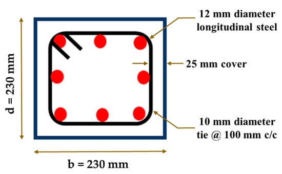
Figure 1.
Sectional details of RC column elements.

Table 1.
Test matrix and strengthening schemes for the proposed work.
3.1. Material Properties
3.1.1. Concrete
The concrete mix design was carried out as per IS10262 -2009 [] to have a target mean cubic compressive strength of 48 MPa (M40) after 28 days of water curing. The mix proportions arrived for this study are: cement = 360 kg/m3; river sand = 752 kg/m3; gravel (blended) = 1196 kg/m3; water = 144 kg/m3 and admixture = 3.6 kg/m3. The average cube compressive strength of concrete was found to be 55 MPa after 28 days of curing.
3.1.2. Steel and FRP Composites
Steel rebars of Fe500 grade were used as both longitudinal and transverse reinforcements. Coupon specimens of steel are prepared and tested under uniaxial tension. The yield strength, ultimate strength and strain were found to be 512 MPa, 620 MPa and 7.8%, respectively. For NSM strengthening, pre-cured CFRP strips of 50 mm × 1.4 mm was availed from the supplier. Three FRP strips of dimensions 12.5 × 1.4 mm were bonded together as a single strip to increase the thickness to 4.2 mm. The surface of the laminates was bonded with the help of two-component epoxy of resin and hardener. For external confinement, unidirectional CFRP fabric was used in this study. Coupon samples were prepared [,] to determine the tensile and compressive properties of the specimen. The test results obtained from the material characterization are reported in Table 2. The details of the test setup for CFRP laminate in tension and compression can be found in other paper of authors [,].

Table 2.
Material characteristics of FRP laminates.
3.2. Test Setup and Instrumentation Details
The test setup of columns under axial compression is shown in Figure 2. The column elements were tested in a compression testing machine of 5000 kN capacity in a displacement controlled mode. The rate of loading was 0.5 mm/min. Capping with the high strength non-shrink grout was provided at the top and bottom surface of the specimens to ensure uniform load distribution and to avoid stress concentrations. The surface undulations in the specimens were removed by loading and unloading the specimens, up to 10% of its expected peak load capacity. The specimens were loaded through displacement control with the help of two Linear Variable Differential Transducers (LVDTs) of 10 mm stroke length. In addition to that, a 50 mm LVDT is added to control the loading protocol when the overall displacement of the specimen exceeded 10 mm. The surface of the column was attached with four LVDT’s of 20 mm stroke and 180 mm gauge length to measure the surface strains and displacements, as shown in Figure 2. Data Acquisition System (DAQ) was used to acquire the test data from LVDT’s and strain gauges. The data of the test specimens were collected at a sampling frequency of 5 Hz.
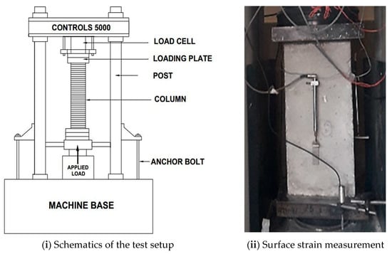
Figure 2.
Test setup and surface strain measurement for RC columns under axial loading.
3.3. Pre-Damaging of Columns
Very few investigations have emphasised to understand the behaviour of pre-damaged concrete members under axial loads [,,,]. In this study, the columns were loaded initially under load control mode up to 80% of the expected peak load for three cycles, which corresponds to a strain close to the peak compressive strain of concrete (εc = 0.002). The rate of loading was kept as 5.2 kN/sec. This type of loading mechanism was chosen so that the stable micro-cracks and bond cracks develop in the concrete column elements with/without longitudinal reinforcement yielding (RC columns). One control specimen of plain and reinforced concrete type was tested until final failure to understand its capacity and failure mechanism. The behaviour of plain and reinforced concrete columns under three cycles of 80% loading are illustrated in Figure 3. The plain concrete columns were loaded until 1600 kN for three cycles whereas the reinforced concrete columns were loaded until 1800 kN. The first cycle of loading represents a stable behaviour. In the subsequent cycles of loading, a reduction in the slope of the specimen indicating degradation in the stiffness. There was a reduction in the initial stiffness of the specimen when compared to the control specimen (C-PC). The columns developed some stable micro-cracks in the specimen. However, there were no major visible cracks found in both the plain and reinforced concrete column elements during cyclic loading. After that, the specimens were strengthened using the near-surface mounting (NSM) technique and hybrid FRP technique.
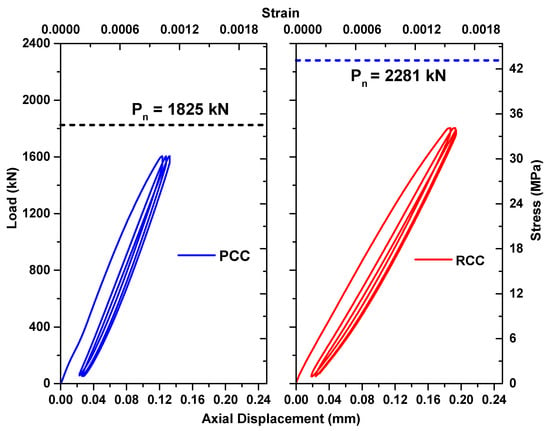
Figure 3.
Cyclic pre-damage of plain concrete and reinforced concrete columns.
3.4. Hybrid FRP Strengthening
The column specimens pre-damaged by cyclic compression were strengthened using two different techniques, namely (a) near-surface mounting strengthening (b) hybrid technique. The concept of hybrid strengthening is used for pre-damaged concrete columns because only external confinement cannot be an ideal solution for (a) columns where combinations of combined compression and bending are dominant and (b) non-circular columns. The hybrid strengthening of columns was carried out as per ACI 440.2R [] provisions. First, the columns are strengthened using the NSM technique followed by external CFRP confinement. The complete details of performing hybrid strengthening were already documented elsewhere [,,,,] and are not repeated for brevity. A schematic illustration of a hybrid FRP technique is shown in Figure 4.
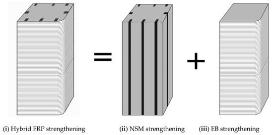
Figure 4.
Schematics of Hybrid FRP strengthening of column.
4. Results and Discussion
Twelve short columns were tested under axial compression out of which six columns were plain concrete columns and the remaining six were reinforced with conventional longitudinal and transverse reinforcements. The failure displacement corresponds to the load level in the post-peak regime when the load drops by 25% (or more) of the peak load. Ductility (µ) is defined as the ratio of displacement at the ultimate load (∆u) to the displacement at yield load (∆y).
4.1. Plain Concrete Columns
Six pre-damaged plain concrete (PC) columns were tested under axial compression. The experimental results are summarised in Table 3.

Table 3.
Test results of pre-damaged PC and RC columns under axial compression.
4.1.1. Load—Displacement Behavior
The plain concrete column (C–PC) represents the behaviour of the control column tested without any pre-damage under axial compression. The specimen had a peak load of 1825 kN corresponding to a displacement of 0.25 mm. The control plain concrete columns were pre-damaged by subjecting to a load of 1600 kN for three cycles. After cyclic pre-damage, no significant reduction in strength of the specimen was observed (Figure 5). However, a good reduction in stiffness and ultimate displacement was witnessed. From Table 3, it can be witnessed that the plain control column (P-PC) had a 14% reduction in axial stiffness. The peak load of specimen P-PC was observed as 1724 kN, which is only 6% lesser when compared to the control specimen (C-PC). The column failed at an ultimate displacement of 0.38 mm, which is about 55.3% lower than the control PC specimen.
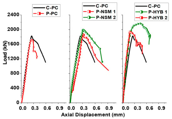
Figure 5.
Overall load-displacement behaviour of pre-damaged PC columns.
NSM strengthening technique improved the behaviour of specimens by providing additional load resistance. The axial stiffness reduced due to pre-damage was restored only up to 96% by NSM strengthening of PC columns. However, the peak load was completely restored to 100% (1941 kN) when compared to the control specimens (C-PC). The column failed at a displacement of 0.84 mm, which was 42.4% higher when compared to the control PC column. The hybrid FRP strengthened specimens were able to restore the axial stiffness, peak strength and ultimate displacement when compared to the control PC columns (C-PC). The columns had an average peak load of 2055 kN. The column failed at an ultimate displacement of 0.59 mm. Using hybrid FRP technique, the restoration in strength was found to be maximum, which is about 12.6% higher than the control column. However, the peak strength was slightly different for both the similar specimens, which can be attributed to the difference in damage that might have arisen due to pre-damage. However, both the specimens completely restored the control capacity when compared to the control column (C-PC). The ultimate displacement was also fully restored with the hybrid FRP technique.
4.1.2. Load—CFRP Strain Behavior
FRP strengthening was able to reduce the overall strain in the specimens when compared to damaged RC specimens (R-RC). Moreover, the hybrid strengthening was able to provide a simultaneous contribution in both longitudinal, transverse reinforcements and CFRP due to which the improvement in overall behaviour was achieved. The transverse strain contribution of CFRP is significant in the case of hybrid strengthening (Figure 6). The effective confinement of NSM laminates using CFRP fabrics helped in resisting the applied additional strain and thereby improved the overall behaviour of the specimen when compared to the only NSM strengthening Scheme.
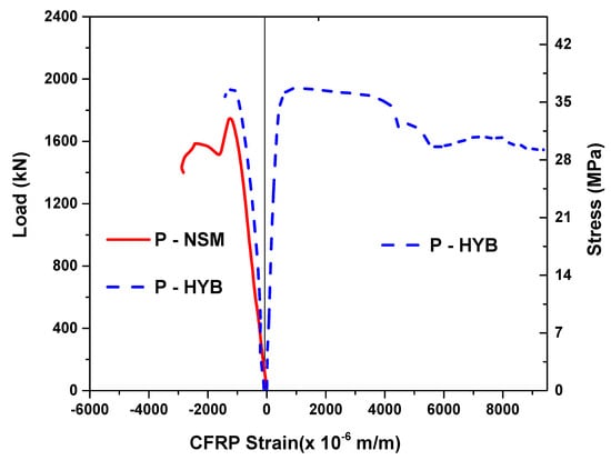
Figure 6.
Load-CFRP strain behaviour of FRP strengthened PC columns.
4.1.3. Failure Mode of PC Columns
In the case of PC columns, initial cracks occurred due to tensile stresses from the Poisson effect in the lateral direction. These cracks widened further towards the corners. The failure occurred due to larger crack width formation and spalling of concrete cover (Figure 7i). The failure of NSM strengthened pre-damaged columns initiated due to cracking between the FRP laminates. The failure was sudden due to compression dominant behaviour (Figure 7iii). The column failure of hybrid pre-damaged specimens initiated due to rupture of FRP followed by propagation of rupture on the corners of the specimen. The failure occurred due to de-lamination of FRP with the cover concrete from the core in a sudden brittle manner (Figure 7iv).
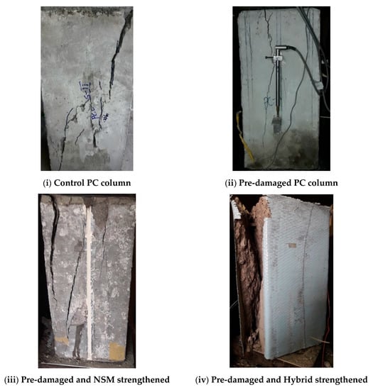
Figure 7.
Failure Modes of Pre-damaged PC Columns with and without FRP Strengthening.
4.2. Reinforced Concrete Columns
4.2.1. Load—Displacement Behavior of RC Columns
The overall behaviour comparison of pre-damaged RC column elements with and without FRP strengthening is illustrated in Figure 8. The horizontal dotted line in the figure refers to the actual load capacity of RC column without any damage (C-RC). RC columns which were pre-damaged by loading up to 1800 kN for three cycles under axial compression are compared with the undamaged control columns (C-RC). The control columns had an average peak load-carrying capacity of 2281 kN corresponding to a displacement of 0.42 mm. The pre-damaged RC column had a peak load of 2006 kN which is 13.6% lesser than the control specimen with the reduced stiffness. The specimen had an ultimate displacement of 1.31 mm.
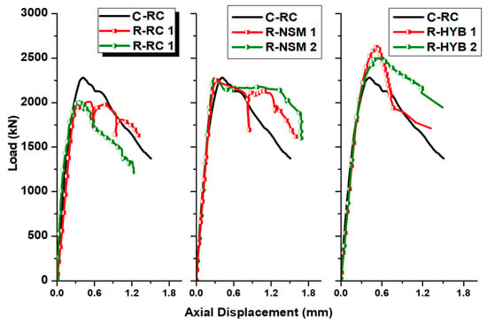
Figure 8.
Overall load-displacement behaviour of pre-damaged RC columns.
The pre-damaged RC columns, which are strengthened using the NSM technique. completely restore the initial stiffness, load carrying capacity and axial ductility when compared to the control un-damaged specimens under pure compression. The average load-carrying capacity of the specimen was found to be 2261 kN, which shows that the peak strength was fully recovered. The displacement ductility at failure was found to be 1.63, which was 8.6% higher than the control RC column (C-RC). The pre-damaged hybrid FRP strengthened RC columns had an average peak load of 2555 kN corresponding to the displacement of 0.53 mm. The hybrid RC specimen was able to increase the peak load capacity by 12% and reached the ultimate displacement up to 90% of control reinforced concrete (C-RC) column without any damage. The confinement pressure supplied by external confinement helps to close the compression cracks and enhance the confined compression strength of pre-damaged columns. The confinement of concrete core also helped the NSM laminates in hybrid specimens to undergo larger strains before failure resulting in the more effective use of the laminates when compared to only NSM strengthening.
4.2.2. Load—Strain Behaviour of RC Columns
FRP strengthening was able to reduce the overall strain in the specimens when compared to damaged RC specimens (R-RC). Moreover, the hybrid strengthening was able to provide a simultaneous contribution in both longitudinal, transverse reinforcements and CFRP due to which the improvement in overall behaviour was achieved. The transverse strain contribution of CFRP is significant in the case of hybrid strengthening (Figure 9). The effective confinement of NSM laminates using CFRP fabrics helped in resisting the applied additional strain and thereby improved the overall behaviour of the specimen when compared to the only NSM strengthening Scheme.
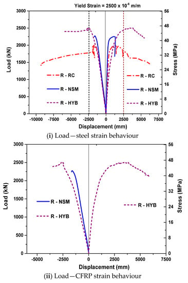
Figure 9.
Load—strain behaviour of Pre-damaged RC columns.
4.2.3. Failure Mode of Pre-Damaged RC Columns
The failure of un-strengthened RC columns initiated due to yielding of the longitudinal bar followed by intense cracking throughout the specimen. The ultimate failure of the specimen occurred due to severe spalling of cover concrete and large crack propagation, as shown in Figure 10. The failure occurred due to local spalling of concrete cover and widened cracks at the increased load levels. The failure of NSM strengthened specimens initiated due to cracking between the NSM FRP laminates, which propagated towards the edges. The failure mode was ductile with a good amount of ductility due to hybrid strengthening scheme irrespective of the initial damage condition of the specimen. The hybrid strengthened specimen had the initiation of failure due to rupture of FRP followed by rapid progression of damage. The control hybrid strengthened specimens failed due to de-bonding of FRP from the concrete cover, whereas the pre-damaged hybrid strengthened specimens failed due to delamination of FRP fabric with the concrete cover. The failure mode was sudden and brittle for the pre-damaged hybrid strengthened specimens.
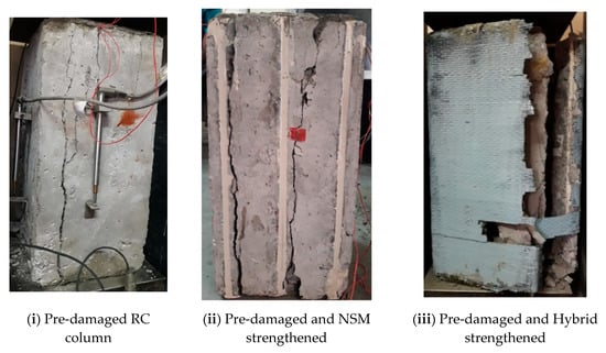
Figure 10.
Failure mode of pre-damaged RC specimens after strengthening.
5. Analytical Studies for Pre-Damaged Columns
Axial load-displacement behaviour of pre-damaged plain and reinforced concrete columns with different strengthening techniques are predicted using sectional level analysis. The contribution of the analytical work from this study includes (i) use of discrete fibre element approach for the analysis of unconfined (plain, control and NSM) and FRP strengthened columns under axial compression, (ii) understanding the contribution of NSM and hybrid FRP technique for both plain and reinforced concrete columns with pre-damage.
5.1. Unconfined Concrete Specimens
The predictions of unconfined specimens (plain, RC and NSM strengthened columns) with initial pre-damage were obtained using the procedure mentioned below.
- (i)
- The cross-section of the specimen was divided into several layers known as fibres. Fibre discretization approach helps in the use of an actual parabolic stress-strain model of concrete rather than the use of idealised rectangular stress block method.
- (ii)
- The nonlinear behaviour of concrete is considered through the Hognestad’s parabolic model [], where the concrete cylinder compressive strength was obtained from the material characterization discussed earlier. In this context, the pre-damaged concrete specimens were assumed to have a significant reduction in strength and stiffness. Therefore, the original constitutive law was modified to represent the behaviour of the pre-damaged concrete columns.
- (iii)
- The stress-strain behaviour of the steel was considered linear until yielding. After that, the strain value increases until the hardening point without an increase in stress (fst). Thus, the increase in both stress and strain was observed after yielding until it reached its ultimate strength.
- (iv)
- Stress in FRP (fN) for a given strain was arrived based on their corresponding stress-strain behavior.
- (v)
- The total load resistance of the specimen was calculated as the sum of resistance from concrete, steel reinforcement and CFRP.
- (vi)
- The axial displacement was computed from the value of initial strain multiplied by the gage length of LVDTs used in the experiments.
For pre-peak region (0 < εc < 0.002), the stress (fc) can be estimated using the Hognestad’s parabolic model [], as given by Equation (1):
where fcm′ = compressive strength of pre-damaged concrete considered to be 0.75 times the compressive strength of actual undamaged concrete under pure compression [,].
For the post-peak region, (0.002< εc < 0.0035), stress (fc) can be calculated by Equation (2):
The total load resistance of the pre-damaged specimen was calculated using Equation (3):
5.2. FRP Confined Concrete Specimens
Stress-strain models for FRP confined concrete were developed by various researchers [,,]. In this study, Lam and Teng’s model [] was used for predicting the confined concrete behaviour. However, to represent the effect of pre-damage, an improvisation in the existing equation is carried out. The step-by-step procedure used in the analysis is as mentioned below.
- (i)
- The cross-section was discretised into a large number of fibres, and the initial strain value was fixed.
- (ii)
- The axial stress in each concrete fibre was calculated using a modified Lam and Teng model, where fcm′ correspond to the compressive strength of pre-damaged concrete considered to be 0.75 times the compressive strength of undamaged concrete. The maximum confined compressive strength of concrete (fcc′) can be calculated in terms of maximum confinement pressure (fl), as mentioned in Equations (4)–(8).
- (iii)
- The contribution of NSM laminates (fN) under compression can be estimated from their respective stress-strain relationship (fN = Ef x εc).
- (iv)
- The total axial load contribution (PT) can be calculated from the load resistance of the concrete, steel and FRP laminates using axial force equilibrium condition.
To estimate the reduction in confinement effect for columns of non-circular section, Lam and Teng [] proposed two critical parameters called as the shape factors (ka and kb) for the strength and strain enhancement calculated using Equation (9). Equation (10) was used to estimate the ratio of effectively confined area to the total gross area of the FRP confined section:
5.3. Comparison of Analytical and Test Results
The analytical predictions are compared with the experimental results and shown in Table 4. Moreover, the overall behaviour predictions are compared with the tests for both plain and reinforced concrete columns and shown in the next section. It is clear that the analytical model was able to closely predict the initial stiffness and peak strength of both the unconfined and confined PC and RC columns. Additionally, the pre-damage index used for including the effect of initial cyclic loads effectively captured the overall load-displacement response of PC and RC columns. The existence of pre-damage results in a significant reduction in the stiffness of the column and a similar response was predicted by the analytical model. The ratio of confined to the unconfined concrete stress ratio (fcc′/fcm′) for pre-damaged and hybrid strengthened specimen was found to be 1.09. For this particular (fcc′/fcm′), the ratio of load carrying capacity for PC (PHYB/PPC) and RC (PHYB/PRC) specimens were 1.25 and 1.23, respectively, which indicates that hybrid strengthening technique is highly effective even for lesser lateral confinement. From the previous studies, it is well established that the efficiency of confinement reduces for non-circular sections due to non-uniform stress re-distribution. In addition to the above non-uniform stress variation, the presence of initial damage can reduce the effectiveness of strengthening procedure adopted. However, hybrid strengthening technique using NSM and EB combinations was very effective in improving the overall performance of pre-damaged square columns of both plain and reinforced concrete type. Comparing the peak strength of both experimental and analytical results, a close match was witnessed for most of the specimen series with the variation of less than 10%. Moreover, the peak strength was under-predicted for most of the specimen series when compared to the tests.

Table 4.
Comparison of peak strength from tests with the analytical and FEM.
6. Three-Dimensional Finite Element Analysis
A phased three-dimensional (3D) nonlinear finite element study for pre-damaged RC columns with and without FRP techniques was carried out using a commercial finite element software ABAQUS []. The nonlinear behaviour of concrete in both tension and compression were modelled using concrete damage plasticity (CDP) model [,,]. The predictions obtained from the FE model are validated with the experimental results. The details of the FE modelling are discussed in the following sections.
6.1. Material Properties
6.1.1. Concrete
Modelling damage in concrete is anisotropic. The damage in concrete can be attributed due to the different mechanisms such as micro-cracking, de-cohesion and coalescence. The plasticity behaviour in concrete was characterised by different parameters such as strain softening, volumetric expansion and progressive deterioration, which in turn leads to the reduction in stiffness and strength. In the concrete damage plasticity model, the degradation in stiffness is initially isotropic and defined by the degradation variables in the compression (dc) and tension zone (dt). The damage factor (d), which accounts for the reduction in stiffness varies between the value of 0 (no damage) and 1 (completely damaged). These damage parameters corresponding to the peak stress to quantify the extent of damage under compression loading. It is worth mentioning that the use of damage variables (dt or dc) with values more than 0.99 can result in convergence issues. Therefore, the damage parameters used in tension (dt) and compression (dc) were given less than 0.99, which correspond to the stiffness reduction of 99%.
Concrete is a non-homogenous material with a high degree of variability. Each loading surface is characterised with the hardening parameter (ku), which controls the evolution of yield surface and degradation of stiffness. In the CDP model, plastic flow is governed by a flow potential G() as per the non-associative flow rule. A modified Hognestad’s equation [] to represent the stress-strain behaviour of concrete in compression and linear-exponential model [] for tension behaviour of concrete is used.
6.1.2. Steel Reinforcement and CFRP
The stress-strain behaviour of the steel reinforcement was modelled using a tri-linear curve considering its strain hardening behaviour. The post-yielding behaviour is defined until the rupture strain of steel. Linear elastic behaviour of FRP strips is provided as input for modelling. In the case of CFRP fabric, the elastic properties are defined using the lamina. Damage properties of NSM laminates are defined using the Hashin’s damage criteria [,].
6.2. Modelling Procedure and Interface Properties
A dynamic explicit modelling procedure was used, since it is capable of yielding a close convergence with the actual value. To ensure the stability of static problem analysed in this study, the ratio of kinetic energy to internal energy obtained was kept less than 0.1. Moreover, the CDP model in ABAQUS considers the non-linear model, which includes the interpolation part of the displacement field and the discontinuous displacement field.
Regarding the interface modelling for the surface between the concrete—steel and between the concrete—NSM reinforcement was modelled as an embedded region, neglecting the effect of bond-slip [,,]. The interface between the concrete surface and FRP fabric was modelled as a surface to surface explicitly where the normal and tangential stiffness properties of epoxy are defined [].
6.3. Boundary Conditions and Meshing
The meshing of concrete and FRP shell elements are shown in Figure 11. Mesh converge study was carried out to determine the optimum mesh size. The mesh size was modified again to have optimum predictions to ensure the convergence. A mesh of size 25 mm was chosen for all the columns tested under axial compression. Concrete is modelled using C3D8R element, i.e., a three-dimensional eight-node element with three translational degrees of freedom at each node. S4R element is used to model the behaviour of CFRP fabric. T3D2 (Three Dimensional Two Node Truss) element is used to model the steel reinforcements and CFRP laminates. To simulate the boundary conditions similar to the experiment, all the base nodes are completely constrained to achieve required numerical stability. The load is applied on a top of the column using a rigid steel plate. The load is applied in the form of incremental displacement (strain controlled procedure) similar to the experiments to capture the complete post-peak behaviour of the column. The displacement limits are provided in a tabular form with the amplitude varying from 0 and 1 mm, which corresponds to the minimum and maximum displacement limits.
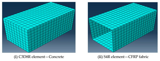
Figure 11.
Meshing of concrete and CFRP fabric using ABAQUS.
6.4. Phased Analysis for Columns with Cyclic Damage
For including the effect of initial cyclic damage in the finite element analysis, staged nonlinear modelling of columns was carried out. Therefore, the modelling procedure for pre-damaged column involves two different stages. The results obtained from the first stage acts as the input for the next stage. In Stage I, compression loads were applied on the columns to induce pre-damage in a load controlled mode up to 80% of its peak load for three cycles. The initial loading induces several micro-cracks and stable mortar cracks in the specimen. These cracks are carried forward to the subsequent stages of analysis using the restart command, i.e., the inputs from the first stage are brought into the next ones. In Stage II of the FE analysis, the FRP materials were modelled for the specimens and loaded in a displacement controlled mode till failure. This means the effect of stable cracks developed during the initial cyclic loading on the strengthening efficacy was taken into consideration by the developed FE model. To improve the rate of convergence in the post-peak regime, the viscosity parameter in CDP model is considered as a smaller value of 0.001, which can help the tangent stiffness of the softening material to become positive for sufficiently smaller time increments.
6.5. Comparison of FE and Test Results
The experimental and FE load-displacement behaviour comparison of PC and RC columns with and without FRP strengthening are shown in Figure 12 and Figure 13, respectively. Table 4 provides the value of peak strength comparisons for different specimen series with pre-damage. Comparing the peak loads, the predictions from the FE analyses were within the difference of 10% when compared to the experiments. The control specimens (PC and RC columns with pre-damage), the FE results were over-predicting the experiments by a small margin of 5% discrepancy. For all the FRP strengthened specimens (NSM and Hybrid), the FE results under-predicted the experimental values. Nevertheless, the overall behaviour in terms of initial stiffness, peak strength and post-peak degradation were better predicted by the developed phased finite element model.
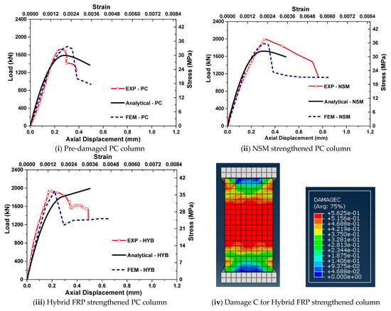
Figure 12.
Comparison of pre-damaged PC columns under axial compression.
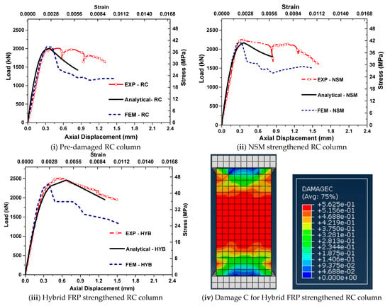
Figure 13.
Comparison of pre-damaged RC columns under axial compression.
From the results shown in Figure 12 and Figure 13, it is clear that the developed FE model was able to predict the overall behaviour of pre-damaged concrete columns in terms of their initial stiffness, peak strength and failure displacement. The post-peak behaviour obtained from the FE model was slightly different from the experiments in some of the cases. It was due to the sudden drop in load observed in the peak due to the crushing of concrete. Nevertheless, the developed FE model captured the overall trend effectively. The damage mechanism and failure modes were represented in terms of damage index in compression (Figure 12iv and Figure 13iv). Damage index corresponds to the level of damage in the member and varies from 0 to 1. The failure modes obtained from FE analyses were similar to the experiments for all the specimen series.
6.6. Parametric Investigation from Validated FE Model
From the finite element model validated with the tests, a detailed parametric study was performed to determine the influence of pre-damage levels, and FRP reinforcement ratios in hybrid strengthened PC and RC columns.
6.6.1. Effect of Pre-Damage Levels in Hybrid FRP Strengthening
The first parametric study was performed to understand different pre-damage levels in hybrid FRP strengthening. The initial pre-damage levels in both PC and RC columns are varied as 40%, 60% and 80% of the maximum peak loads. From Figure 14, it is clear that the increase in the damage level has no significant reduction in the efficiency of hybrid FRP strengthening in terms of their compressive strength and displacement. However, for the columns with 80% pre-damage (0.8 Po), a significant reduction in the axial stiffness was observed when compared with the hybrid specimens with low pre-damage levels (0.4 Po, 0.6 Po). Moreover, the peak strength of hybrid PC and RC columns with 80% preload was slightly high compared to the low pre-damaged specimens, which show the increase in contribution from NSM laminates and confinement with the higher levels of initial damage.
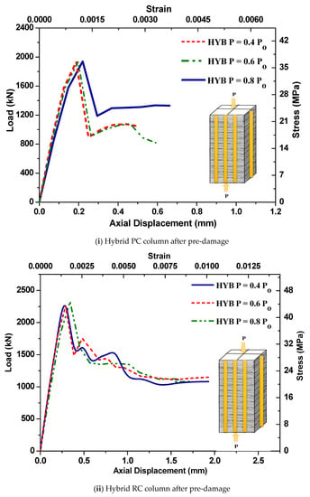
Figure 14.
Effect of pre-damage levels on hybrid FRP strengthening.
6.6.2. Effect of FRP Reinforcement Ratios in Hybrid FRP Strengthening
The second parametric study was to investigate the effect of FRP reinforcement ratios in the hybrid strengthening of PC and RC columns with pre-damage. For a constant FRP confinement ratio of 0.7%, the NSM laminate ratio was varied from 0.4% to 1.2%. The ratios were selected to provide optimum strengthening practices considering the levels of additional reinforcements required from external FRP strengthening. From Figure 15, it is clear that the increase in NSM laminate ratio improved the peak strength for both PC and RC hybrid columns with 80% pre-damage. However, when the FRP laminate ratio (ρfl) was increased more than 1.2%, no significant improvement in strength was observed.
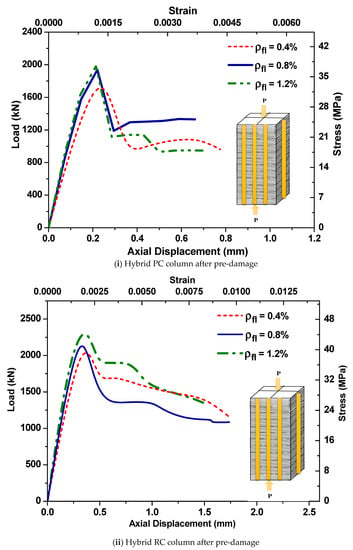
Figure 15.
Effect of FRP reinforcement ratios on the hybrid strengthening of pre-damaged columns.
7. Summary and Conclusions
The pre-damaged columns under cyclic compression were strengthened using a hybrid FRP composite system and tested to failure. The compression behaviour of the hybrid FRP-retrofitted pre-damaged columns was investigated in detail. Various factors that influence the effectiveness of hybrid FRP-retrofitted pre-damaged columns were analysed. Based on the results presented in this study, the following significant conclusions can be drawn:
- Both the FRP strengthening schemes (NSM and Hybrid) effectively restored the initial stiffness and load-carrying capacity of the columns after cyclic compressive damage.
- NSM strengthening of plain concrete columns increased the overall performance in terms of its load-carrying capacity and ultimate displacement. Moreover, the failure occurred in a ductile manner through the propagation of cracks in the concrete between the NSM FRP laminates.
- In the hybrid FRP strengthening of plain concrete columns, NSM laminates acted effectively as longitudinal reinforcement. The load contribution of NSM laminates was found to be significant from the measured load-strain diagram. Moreover, the effectiveness of NSM laminates significantly increased due to external confinement of CFRP fabric.
- RC columns strengthened using the NSM strengthening technique fully restored the capacity lost due to the initial cyclic damage. The increase in strength and ultimate displacement of NSM strengthened RC column was negligible and 10%, respectively, when compared to the control column element (C-RC).
- Hybrid FRP strengthening technique was able to increase the strength up to 12% and ultimate displacement was restored to 94% of its control capacity when compared to the column without any initial damage (C-RC).
- The analytical approach used in this work closely predicted the behaviour of both plain and reinforced concrete columns strengthened using NSM and hybrid FRP techniques.
- The results from the staged FE modelling exhibited a good correlation with the test results showing the reliability of the FE modelling approach to include the effect of pre-damage. The detailed parametric investigation from this study highlights an important observation, namely that the different levels of pre-damage have no significant impact on strength improvement due to hybrid FRP strengthening.
Author Contributions
M.C., S.J., S.S.P. and A.S. designed the test matrix. M.C. and S.J. performed the experiments. M.C., S.J., S.S.P. and A.S. wrote the paper.
Funding
This research was funded by the FAST-Center for Sustainable Development, Ministry of Human Resource Development, Government of India.
Acknowledgments
The authors would also like to acknowledge the help of P. Amrudha, Project Assistant, Indian Institute of Technology Hyderabad for her inputs and help with the finite element modelling.
Conflicts of Interest
The authors declare no conflict of interest.
Abbreviations
The following symbols are used in this paper:
| Ac = total area of the concrete section (mm2). |
| Ae = total area of the effectively confined concrete section (mm2). |
| Ag = total gross area of the concrete section (mm2). |
| b = breadth of the member (mm) |
| d = sectional depth excluding the concrete cover (mm). |
| d′ = thickness of concrete cover (mm). |
| di = distance of steel reinforcement with respect to the position (mm). |
| dN,i = distance of NSM reinforcement with respect to the position (mm). |
| E2 = slope of linear portion in the stress-strain curve for the concrete confined with FRP (MPa). |
| Ec = modulus of elasticity of concrete (MPa). |
| Ef = modulus of elasticity of FRP in tension (MPa). |
| εc = compressive strain in the top face of the section. |
| εc′ = maximum compressive strain of concrete without confinement. |
| εcu = failure strain level in concrete without confinement. |
| εcm = ultimate strain of unconfined concrete with pre-damage. |
| εccu = failure strain level in concrete with FRP confinement. |
| εfu = strain in FRP corresponding to rupture. |
| εfe = effective strain level in FRP reinforcement at failure. |
| εs,i = strain in the steel at different levels of the section. |
| εt′ = transition strain in the stress-strain curve of CFRP confined concrete. |
| εy = yield strain of steel reinforcement in tension. |
| fc = average cylinder compressive strength of concrete without confinement (MPa). |
| fc′ = compressive stress in concrete (MPa). |
| fcc′ = compressive strength of FRP confined concrete (MPa). |
| fcm′ = modified compressive strength of unconfined concrete with pre-damage (MPa). |
| fl = maximum confining pressure owing to CFRP fabric (MPa). |
| fst = overall stress contribution from steel reinforcement (MPa). |
| fN = overall stress contribution from NSM laminates (MPa). |
| κε = strain efficiency factor of FRP. |
| n = number of plies of FRP reinforcement. |
| PT = total sectional capacity in terms of load (kN). |
| rc = corner radius of non-circular sections confined using FRP (mm). |
| ψf = Reduction factor for FRP. |
| tf = nominal thickness of FRP for one ply (mm). |
References
- Parvin, A.; Brighton, A. Fiber reinforced polymer composites strengthening of the concrete column under various loading conditions. Polymers 2014, 6, 1040–1056. [Google Scholar] [CrossRef]
- Herwig, A.; Motavalli, M. Axial behavior of square reinforced concrete columns strengthened with lightweight concrete elements and unbonded GFRP wrapping. J. Compos. Constr. 2016, 16, 747–752. [Google Scholar] [CrossRef]
- Song, X.; Gu, X.; Li, Y.; Chen, T.; Zhang, W. Mechanical behavior of FRP strengthened concrete columns subjected to concentric and eccentric compression. J. Compos. Constr. 2013, 17, 336–346. [Google Scholar] [CrossRef]
- Maaddawy, T.; Sayed, M.; Magid, B.A. Effect of cross-sectional shape and loading condition on the performance of reinforced concrete members confined with carbon fiber reinforced polymers. Mater. Des. 2013, 31, 2330–2341. [Google Scholar] [CrossRef]
- Chellapandian, M.; Prakash, S.S.; Sharma, A. Experimental investigation on the effectiveness of Hybrid FRP strengthened RC columns on axial compression—Bending interaction behavior. J. Compos. Constr. 2019, 23, 04019025. [Google Scholar] [CrossRef]
- Chellapandian, M.; Prakash, S.S.; Mahadik, V.; Sharma, A. Experimental and Numerical Studies on the Effectiveness of Hybrid FRP Strengthening on Behavior of RC Columns under High Eccentric Compression. J. Bridge Eng. 2019, 24, 04019048. [Google Scholar] [CrossRef]
- Hadi, M.N.S. Behavior of FRP strengthened concrete columns under eccentric compression loading. Compos. Struct. 2007, 77, 92–96. [Google Scholar] [CrossRef]
- Hadi, M.N.S.; Zhao, H. Experimental study of high strength concrete columns confined with different types of mesh under eccentric and concentric loading. J. Mater. Civ. Eng. 2013, 23, 823–832. [Google Scholar] [CrossRef]
- Ghernouti, Y.; Li, A.; Rabehi, B. Effectiveness of repair on damaged concrete columns by using fiber-reinforced polymer composite and increasing concrete section. J. Reinf. Plast. Compos. 2012, 31, 1616–1629. [Google Scholar] [CrossRef]
- Al-Nimry, H.S.; Ghanem, A.M. FRP confinement of heat-damaged circular RC columns. Int. J Concr. Struct. Mater. 2017, 11, 1–19. [Google Scholar] [CrossRef]
- Fukuyama, K.; Higashibata, Y.; Miyauchi, Y. Studies on repair and strengthening methods of damaged reinforced concrete columns. Cem. Concr. Compos. 2000, 22, 81–88. [Google Scholar] [CrossRef]
- Li, G.; Hedlund, S.; Pang, S.S.; Alaywan, W.; Eggers, J.; Abadie, C. Repair of damaged RC columns using fast curing FRP composites. Compos. Part B Eng. 2003, 34, 261–271. [Google Scholar] [CrossRef]
- Ferrotto, M.F.; Fischer, O.; Niedermeier, R. Experimental investigation on the compressive behavior of short term preloaded CFRP-confined concrete columns. Struct. Concr. 2017, 19, 1–14. [Google Scholar]
- Ferrotto, M.F.; Fischer, O.; Niedermeier, R. Analysis-oriented stress–strain model of CRFP-confined circular concrete columns with applied preload. Mater. Struct. 2018, 51, 44. [Google Scholar] [CrossRef]
- Montuori, R.; Piluso, V.; Tisi, A. Ultimate behaviour of FRP wrapped sections under axial force and bending: Influence of stress-strain confinement model. Compos. Part. B Eng. 2013, 54, 85–96. [Google Scholar] [CrossRef]
- Chellapandian, M.; Prakash, S.S.; Sharma, A. Experimental and finite element studies on the flexural behavior of reinforced concrete elements strengthened with Hybrid FRP technique. Compos. Struct. 2019, 208, 466–478. [Google Scholar] [CrossRef]
- Chellapandian, M.; Prakash, S.S. Axial compression—Flexure interaction behavior of hybrid fiber-reinforced polymer-strengthened columns. ACI Struct. J. 2019, 116, 125–138. [Google Scholar] [CrossRef]
- Indian Standards 10262. Recommended Guidelines for Concrete Mix Design; Bureau of Indian Standards: New Delhi, India, 2009. [Google Scholar]
- ASTM D3039. Standard Test Method for Tensile Properties of Polymer Matrix Composite Materials; ASTM 2000; ASTM International: West Conshohocken, PA, USA, 2017. [Google Scholar]
- ASTM. D 6484M. Standard Test Method for Compressive Strength of Polymer Matrix Composite Laminates; ASTM 1999; ASTM International: West Conshohocken, PA, USA, 2014. [Google Scholar]
- Chellapandian, M.; Prakash, S.S.; Sharma, A. Strength and ductility of innovative hybrid NSM reinforced and FRP confined short RC columns under axial compression. Compos. Struct. 2017, 176, 205–216. [Google Scholar] [CrossRef]
- Chellapandian, M.; Prakash, S.S. Behavior of FRP strengthened RC columns under pure compression—Experimental and numerical studies. In Recent Advances in Structural Engineering: Select Proceedings of SEC 2016; Springer: Singapore, 2019; pp. 663–673. [Google Scholar]
- Dalgic, K.D.; Ispir, M.; Binbir, E.; Ilki, A. Effects of pre-damage on axial behavior of CFRP jacketed non-circular members. In Proceedings of the Conference on Civil Engineering Infrastructure based on Polymer Composites 2012, Krakpw, Poland, 22–23 November 2012. [Google Scholar]
- Ilki, A.; Kumbasar, N. Behavior of damaged and undamaged concrete strengthened by carbon fiber composite sheets. Struct. Eng. Mech. 2002, 13, 75–90. [Google Scholar] [CrossRef]
- Manos, G.C.; Stavroy, D.S.; Dimosthenous, M.A.; Kourtides, B. Experimental and analytical investigation of repaired and strengthened reinforced concrete structural elements utilizing CFRP. In Proceedings of the 13th World Conference on Earthquake Engineering, Vancouver, BC, Canada, 1–6 August 2004; p. 91. [Google Scholar]
- Ilki, A.; Peker, O.; Karamuk, E.; Demir, C.; Kumbasar, N. FRP retrofit of low and medium strength circular and rectangular reinforced concrete columns. J. Mater. Civ. Eng. 2008, 20, 169–188. [Google Scholar] [CrossRef]
- ACI 440.2R. Guide for the Design and Construction of Externally Bonded FRP System for Strengthening Concrete Structures; ACI Committee 440; American Concrete Institute: Farmington Hills, MI, USA, 2017; p. 45. [Google Scholar]
- Hognestad, E.; Hanson, N.W.; McHenry, D. Concrete stress distribution in ultimate strength design. ACI J. Proc. 1955, 52, 475–479. [Google Scholar]
- Chellapandian, M.; Prakash, S.S. Rapid repair of severely damaged reinforced concrete columns under combined axial compression and flexure: An experimental study. Constr. Build. Mater. 2018, 173, 368–380. [Google Scholar] [CrossRef]
- Chellapandian, M.; Prakash, S.S.; Sharma, A. Axial compression—Bending Interaction behavior of severely damaged RC columns rapid repaired and strengthened using Hybrid FRP composites. Constr. Build. Mater. 2019, 195, 390–404. [Google Scholar] [CrossRef]
- Lam, L.; Teng, J.G. Design-oriented stress-strain model for FRP confined concrete. Constr. Build. Mater. 2003, 17, 471–489. [Google Scholar] [CrossRef]
- Cavaleri, L.; Trapani, F.D.; Ferrotto, M.F.; Davì, L. Stress-strain models for normal and high strength confined concrete: Test and comparison of literature models reliability in reproducing experimental results. Ingegneria Sismica 2017, 34, 114–137. [Google Scholar]
- Montuori, R.; Piluso, V.; Tisi, A. Comparative analysis and critical issues of the main constitutive laws for concrete elements confined with FRP. Compos. Part. B Eng. 2012, 43, 3219–3230. [Google Scholar] [CrossRef]
- ABAQUS User’s Manual 6.11 Providence; SIMULIA; RJ Parker Publisher: Toronto, ON, Canada, 2011.
- Chellapandian, M.; Prakash, S.S.; Rajagopal, A. Analytical and finite element studies on Hybrid FRP strengthened RC column elements under axial and eccentric compression. Compos. Struct. 2018, 184, 234–248. [Google Scholar] [CrossRef]
- Mondal, T.G.; Prakash, S.S. Non-linear finite element analysis of RC bridge columns under torsion with and without axial compression. J. Bridge. Eng. 2015, 13, 04015037. [Google Scholar]
- Yu, T.; Teng, J.G.; Wong, Y.L.; Dong, S.L. Finite Element Modeling of Confined Concrete-II Plastic Damage Model. Eng. Struct. 2010, 32, 680–691. [Google Scholar] [CrossRef]
© 2019 by the authors. Licensee MDPI, Basel, Switzerland. This article is an open access article distributed under the terms and conditions of the Creative Commons Attribution (CC BY) license (http://creativecommons.org/licenses/by/4.0/).