Review

3D Printed Hollow-Core Terahertz Fibers

by
Alice L. S. Cruz
1,2,*,
Cristiano M. B. Cordeiro
3 and
Marcos A. R. Franco
1,2
1
Instituto Tecnológico de Aeronáutica—ITA, São José dos Campos 12228-900, Brazil
2
Instituto de Estudos Avançados—IEAv, São José dos Campos 12.228-001, Brazil
3
Instituto de Física Gleb Wataghin, Universidade Estadual de Campinas—UNICAMP, Campinas 13083-970, Brazil
*
Author to whom correspondence should be addressed.
Fibers 2018, 6(3), 43; https://doi.org/10.3390/fib6030043
Submission received: 22 May 2018 / Revised: 14 June 2018 / Accepted: 15 June 2018 / Published: 21 June 2018
(This article belongs to the Special Issue Hollow Core Optical Fibers)

Abstract

:
This paper reviews the subject of 3D printed hollow-core fibers for the propagation of terahertz (THz) waves. Several hollow and microstructured core fibers have been proposed in the literature as candidates for low-loss terahertz guidance. In this review, we focus on 3D printed hollow-core fibers with designs that cannot be easily created by conventional fiber fabrication techniques. We first review the fibers according to their guiding mechanism: photonic bandgap, antiresonant effect, and Bragg effect. We then present the modeling, fabrication, and characterization of a 3D printed Bragg and two antiresonant fibers, highlighting the advantages of using 3D printers as a path to make the fabrication of complex 3D fiber structures fast and cost-effective.

1. Introduction

The terahertz (THz) spectral range is the part of the electromagnetic spectrum between 0.1–10 THz or 0.03–3 mm wavelength. For a long period, the terahertz band was relatively unexplored due to the unavailability of cost-effective and powerful sources. Due to the evolution of these devices in the mid-1980s, however, terahertz radiation has attracted much more attention. Since this part of the spectrum is between the infrared (IR) and microwave frequency ranges, the development of waveguides [1,2,3,4,5,6], filters [7,8], polarizers [9,10], lenses [11,12], and other optical components benefits from the well-established technologies [13,14,15]. The characteristic of terahertz waves to penetrate most dielectric materials offers the possibility of many applications. The shorter wavelengths than microwave and millimeter waves allow much greater resolution in imaging, making it suitable for security scanning, imaging, and non-destructive testing [16,17]. Because of the non-ionizing characteristic of terahertz, it can pass through organic tissue without causing damage, and it can be safely applied in biomedical sensing [18,19]. In addition, it is possible to detect many chemicals and biological agents because they exhibit well defined spectral signatures in the terahertz range [20,21]. Radio astronomy and wireless communication are also fields with great interest in this spectral range. For example, terahertz waves could be used to detect cold bodies and debris in space or to increase data transmission using the larger bandwidth of the terahertz band [22,23,24,25].
Most terahertz systems are based on free-space propagation, which can control the high losses that occur as a result of absorption by water vapor. However, most terahertz sources and detectors are power inefficient and, in a free-space configuration, path power loss is a significant limitation. Moreover, free-space systems handicap integration with other components. In order to upgrade these systems to use guided waves one needs low-loss and low dispersion propagation waveguides as basic components. These waveguides can provide the transference of electromagnetic waves/information between two points and interconnect systems [4,5,26,27,28,29,30,31]. Furthermore, they can also be explored as sensors and imaging probes [21,32,33].
Over the last decade, a substantial amount of effort has been directed towards achieving significant low-loss terahertz fibers and waveguides. Some works show metal rods being used as terahertz waveguides, but finite conductivity limits their applications [34,35]. An alternative is to fabricate dielectric waveguides. Polymer optical fiber technology and simple designs, such as a rod or a dielectric tube, were initially investigated [36,37,38]. However, dielectric waveguides are lossy due to the bulk material absorption. Polymers, such as Zeonex® and Topas® (Cyclic Olefin Polymers), have losses with typical values of approximately 1 dB/cm [36] while silica, an usual glass used in optical fibers, has a typical loss of approximately 9 dB/cm [39,40]. The first terahertz dielectric waveguide designs tried to explore the concept of reducing the losses by increasing the air filling fraction of porous polymer fibers [41,42,43,44]. Many different configurations have been demonstrated: periodically microstructured fibers [36,37]; bandgap fibers [43]; fibers with elliptical air-holes; and fibers with rectangular slot air-holes to increase the birefringence [5,26,27]. Some waveguide designs have shown interesting results in terms of low-loss and low dispersion over certain frequency ranges [4,6,30,33]. For example, in [4] the authors achieved an effective material loss of 0.034 cm−1 at 1.0 THz. In spite of these results, issues such as broadband transmission, lower losses, low bending losses, easier cutting and splicing procedures, and availability in long lengths are still a challenge [1,30,41,43,45].
However, even with these achievements, the material losses are still high in porous terahertz fibers and the best option to overcome this issue is to move on to hollow-core fibers. Hollow-core fibers are good candidates for low-loss guidance because the material absorption loss can be significantly minimized. This reduction is mostly due to the modal energy being located within the cladding air-holes or air-core, reducing the effective material loss to less than 1/20th of the characteristic loss of the host material. The mentioned fibers and fibers’ preforms can be fabricated via extrusion, stack-and-draw, and drilling and molding, but the fabrication of more complex structures, with higher air filling fraction, can be greatly simplified with more advanced manufacturing techniques.
The recent developments in rapid prototyping, from jewelry to food, have been shown as a path to meet the fabrication of complex 3D structures quickly and cost-effectively. Not only fibers but antennas, couplers, and metallic waveguides have been investigated and fabricated for GHz and THz frequencies [46,47]. The additive manufacturing technique creates structures layer by layer. Among the different additive manufacturing methods, polymer jetting (Polyjet) is the most commonly applied for the fabrication of millimetric and sub-millimetric components due to its superior spatial resolution around 100 μ m .
This paper reviews the evolution of 3D printed hollow-core terahertz fibers, from the first terahertz fiber fabricated using knowledge from photonic crystal fibers (PCF) to the most recent achievements using additive manufacturing (3D printing). The paper is organized as follows: Section 2 outlines the evolution of additive manufacturing and its challenges. Section 3 relies on 3D printed hollow-core terahertz fibers. Section 4 focuses on numerical modeling and experimental characterization of a hollow-core terahertz Bragg fiber and two antiresonant fibers and, in Section 5, concluding remarks are presented as well as a brief discussion on the future.

2. Additive Manufacturing Technology

The first three-dimensional object created layer by layer via additive manufacturing (or 3D printing) was in the 1980’s on the rapid prototyping field. Since then, this technology has revolutionized the manufacturing industry as well as research. Now, cost-effective, customizable, and quick fabrication is enabling the creation of prototypes or finished products with more efficiency. Additive manufacturing builds these objects by adding layers of material instead of removing material from a bulk, as in the milling process for example. Many different materials can be used in additive manufacturing such as polymers, metal [48], biocompatible material [49], ceramic [50] and organic compounds. Therefore, many different industries such as food [51], medical [52], pharmaceutical [53], mechanical [54], and microwaves [46] benefit from the technology.
Additive manufacturing can be split into several branches depending on the fabrication method. These branches include Fused Deposition Modeling (FDM), Stereolithography (SLA), Electron Beam Melting (EBM), Selective Laser Sintering (SLS), Polymer Jetting (Polyjet), and so on [55]. The common process of these methods is the model design, generally drawn in CAD software, converted to a STL file, and sent to the printer.
In the microwave and sub-millimetric wave fields, the use of additive manufacturing has grown. Recent works report the fabrication of waveguides, beam splitters, plasmonic devices, lenses, and antennas [56,57,58,59]. This great interest is due to the compatibility of the fabrication scale, the availability of several materials, fast processes, reproducibility, and low cost. For terahertz devices, the most common methods are fused deposition modelling (FDM), stereolithography apparatus (SLA) and Polyjet. In the FDM process, thermoplastic filaments are heated, extruded through a nozzle and subsequently deposited on the building bed. Its spatial resolution is given by the nozzle opening. The common materials are acrylonitrile butadiene styrene (ABS), polylactic acid (PLA), and polycarbonate (PC). In the SLA process a UV laser beam scans the surface of a photo-resin tank to form each layer of the object. In the Polyjet technique, a print head deposits thin layers of a UV-curable resin onto a construction tray. UV lamps cure the material as it is being deposited. After finishing one cross-section sheet another top layer is built. The advantage of Polyjet over the other methods is its superior spatial resolution of about 100 μ m , which depends on the laser spot size.
One of the actual challenges for additive manufacturing is to produce complex components with high density ceramics. The ceramics are generally processed as powders and present high melting temperatures. Also, they are not resistant to thermal shocks. The most recent advance on this technology shows the application of SLA with ceramic suspension as the way to fabricate dense ceramics. Some commercial solutions are available, such as Admatec Europe. For terahertz devices, the main challenges of using these techniques are: building long length structures; high absorption losses of the available materials; surface finish; and the spatial resolution. Some authors have shown the fabrication of fibers’ preforms with 3D printers and following that the fiber drawing [60] (what improves the finishing), terahertz optics devices printed with Topas (low-loss polymer) [61], and extremely high resolution fabrication (around 1 μ m ) [62]. These recent researches and innovations shown the great scientific interest in using additive manufacturing as a fabrication method. These achievements can lead the technology to become the main fabrication method of terahertz passive devices, keeping in mind the cost-efficiency of the technology.

3. Terahertz 3D Printed Waveguides

The terahertz waveguides should be able to promote propagation of the waves in dry air to decrease the material absorption contribution. To achieve this goal one of these three physical phenomena must occur: the photonic bandgap; the antiresonant effect; or the Bragg reflection. The photonic bandgap effect occurs in hollow-core fibers whose microstructured cladding has an appropriate distribution of air holes. In the bandgap condition, the terahertz modes cannot be guided in certain frequency ranges. The antiresonant effect occurs when the light launched in the fiber core is reflected on both interfaces of the core wall and a constructive interference occurs within the hollow-core. The transmission spectrum of such fibers can be easily obtained by knowing the contrast refractive indexes between clad and core as well as the capillary wall thickness, which is similar to a Fabry–Pérot cavity. Usually these fibers have a far simpler geometrical design than an ordinary tube (capillary). Another class of hollow-core fibers is based on structures with a cladding formed by a succession of material layers with low and high refractive indexes, giving rise to a kind of Bragg reflector known as OmniGuide or Bragg fibers [63].
Based on these physical phenomena, since 2011 researchers have been proposing new designs of air core terahertz fibers using 3D printing as a fabrication method. The first reported 3D printed fiber (Figure 1b) was based on a hollow-core PCF-like structure that was fabricated using the Polyjet technique [64]. In this case, it was possible to achieve a propagation loss of 0.03 dB/mm (0.3 dB/cm) at 105 GHz by applying a UV-resin with a dielectric constant of 2.75. In 2016, another terahertz hollow-core fiber based on photonic bandgap propagation and fabricated via Polyjet was proposed, see Figure 1c [65]. The fiber was printed using a 3D printer with a resolution of 600 dpi and a UV-curable polymer. One of the challenges using 3D prototyping is to build longer length structures since the currently available printers have a strict work-volume limitation. In order to overcome this issue, the authors printed two fibers and connected them mechanically, obtaining an average power propagation loss of 0.02 cm−1 (0.08 dB/cm) over 0.2–1.0 THz. Other authors are investigating the possibility of fabricating the preform of the terahertz fibers directly by 3D printing [60].
The next category of hollow-core printed fibers is based on the antiresonant effect with negative curvature in the core. In a negative curvature fiber, we have the surface normal vector of the core boundary directed towards the fiber’s center [66]. This negative curvature helps to inhibit coupling between the fundamental core mode and the cladding modes, which considerably decreases the propagation losses. In Figure 1d, one can see the cross-section of a fiber fabricated via FDM. This fiber, built with ABS, was able to guide with low-loss in the transmission windows between 0.10–0.21, 0.30–0.40, and 0.5–1.1 THz [67]. The fiber whose cross section is shown in Figure 1e was fabricated using PC via the FDM technique and guides terahertz radiation with losses around 10’s dB/cm over a 150 to 600 GHz range [68].
The last group of fibers (Figure 1f–h) is based on the Bragg reflection. The characteristics of the first 3D printed Bragg fiber is all detailed in [69], see Figure 1f. Using the FDM technology and an ABS polymer, the authors were able to demonstrate low-loss propagation in a 93 mm long fiber. The authors in [70] showed the application of a 3D printed terahertz Bragg fiber as a powder and thin film sensor with sensitivity close to 0.1 GHz/μm (Figure 1g). The fiber was built using an SLA system, which has a transverse resolution of 50 μm and a longitudinal resolution of 1 μm. The printing resin has a refractive index and an absorption coefficient of around 1.64 and, 1.1 cm−1 at 0.2 THz, respectively. This fiber can propagate with low-loss propagation of 0.15 cm−1 (0.65 dB/cm) over frequencies higher than 0.35 THz. The cross-section of the single-mode and low-loss terahertz Bragg fiber presented in [71] can be seen in Figure 1h. The authors reached single mode propagation and an average propagation loss of around 3 dB/m (0.03 dB/cm) at 0.27 THz. Table 1 summarizes the main characteristics of the cited fibers.
The porous fiber (Figure 1a) is easily obtained by drilling and drawing a plastic preform, but the design is limited by how thin the wall thickness can be during the drilling process. However, some energy will still overlap the lossy material leading to high absorption loss. The hollow-core bandgap fibers (photonic crystal and Bragg fibers) may decrease the propagation losses by guiding the wave in the air core, but normally this mechanism works in quite limited wavelength range (Figure 1b,c,f–h). This wavelength range can be broadened by using antiresonant hollow-core fibers (Figure 1d,e). In addition, negative curvature structures can avoid/reduce the coupling between the core/cladding modes, thereby decreasing the propagation loss.

4. Optical Characterization: Numerical Modeling and Experimental Data

In this section, we will present data from some of the 3D printed terahertz hollow-core fibers produced and studied by our research group in the last few years. We will focus on antiresonant and Bragg fibers, once they may present lower absorption and confinement losses. The Finite Element and Beam Propagation Method (FEM and BPM) were used to numerically model the transmittance spectrum of those waveguides. They were manufactured using a desktop 3D printer based on FDM as well as SLA [55].
The FDM printer used, Orion Delta (SeeME CNC), has an approximate resolution of 400 μm defined by an opening of the extruder nozzle that deposits polymer layers with thickness varying from 50 μ m to 100 μ m . The polymer used in this case was ABS. Also, the SLA printer Form 1+® (Formlabs) was used in this paper. The printer resolution depends on the laser spot size on the printer plane and on the displacement along the z-axis, being around 150 μm and 50 μm respectively.

4.1. Numerical Modeling

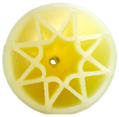
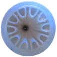
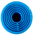
The simulated and fabricated fibers have the geometrical parameters described in Table 2, where Dcore is the internal core diameter, Dext is the external fiber diameter, eh is the thickness of the high refractive index layer, el is the thickness of the low refractive index layer, and L is the fiber length. The antiresonant waveguide A (ARROW A) and the Bragg fiber were built via the FDM technique using ABS—which has a real refractive index around 1.6 at 1.0 THz and an imaginary part presented in [72] (material loss from 21 to 78 dB/cm in the 0.1–1.0 THz range). ARROW B was created via SLA [73]. The host material has a refractive index around 1.65 and an absorption coefficient of about 11 cm−1 at 1.0 THz (material loss of 47 dB/cm) [74].
The Bragg fiber design is based on five concentric polymer rings (eh) separated by air layers (el). The ARROWs have negative curvature in the core. The first is based on the design of a silica hollow-core fiber [75] and the second is inspired by a core surrounded by nested capillaries.
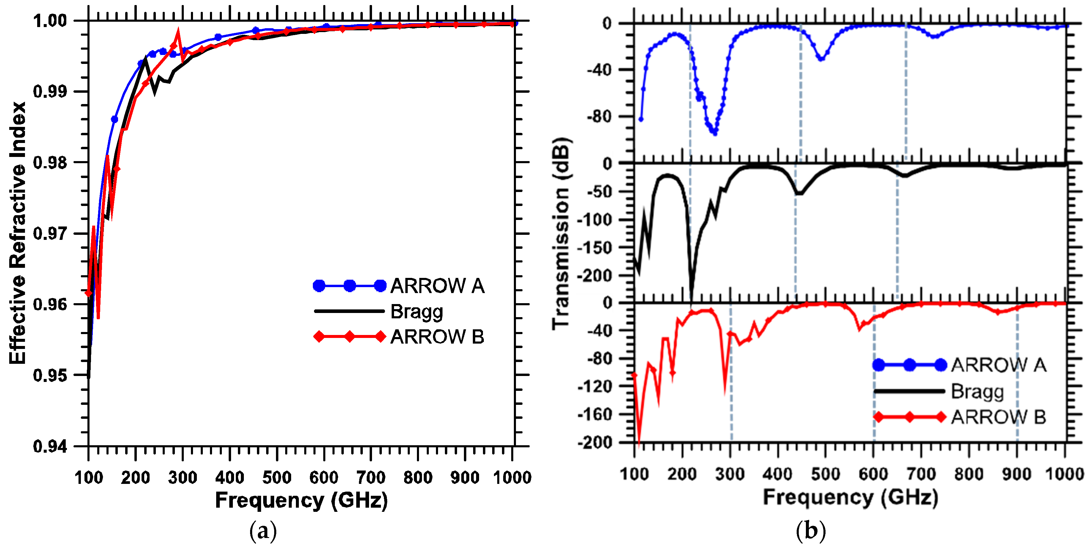
Figure 2a shows the core mode effective refractive index calculated with the commercial software COMSOL® in the range of 0.1 to 1.0 THz. The fluctuation in the dispersion curves are related to the coupling between core and cladding modes. When an effective index phase match occurs, a resonant condition is reached. In those frequencies there is a strong exchange of energy between both core and cladding modes, leading to a higher confinement loss and oscillations showing in the dispersion curve. Fibers fabricated with thinner polymer web structures could reduce this undesirable mode coupling condition.
Figure 2b shows the spectral transmission calculated for the three fiber samples in the same frequency range. Windows of low-loss propagation for all fibers can be observed. These windows are mainly related to the antiresonant propagation condition between two consecutive high loss resonances, where the fibers guide with losses smaller than 3 dB/m.
A simple analytical equation can predict the resonant frequency, taking into account the refractive index and thickness of the solid ring around the air core (dashed gray line in Figure 2b) [67]. It can be seen that these frequencies match the numerical data for the Bragg Fiber well. For the ARROW fibers, however, the analytical equation cannot predict precisely the resonances since the cores are not a perfect ring. Also, we see low-loss propagation windows in the Bragg fiber that match the calculated resonant frequencies. Consequently, it is possible to affirm that the main phenomena supporting the terahertz propagation is also the antiresonant effect at the first polymeric ring. However, using other materials with a lower refractive index contrast than polymer and air can allow the fiber to guide waves via Bragg reflections. Note that, the main geometrical parameter that affects the 3D printed fiber loss is the polymer thickness (eh) [38]. Decreasing eh shifts the transmission peaks to higher frequencies, and reduces the number of polymer/core mode couplings.

4.2. Experimental Characterization

The most common method used to characterize terahertz waveguides is the measurement of the transmission mode using a time domain spectrometer (TDS). Two terahertz electric pulses are measured, as shown in the Figure 3 inset. The first one, named reference pulse, is measured with all optics described in [1] except the waveguide. After that, a second pulse with the waveguide in the sampling area is taken, called a sample pulse. As demonstrated in [1], the loss and dispersion parameters can be calculated from these pulses.
Figure 3a shows the numerically and experimentally obtained spectral transmission of ARROW A (red and blue curves). During the numerical analyses, the polymer absorption was not considered. It was observed that the numerical data can predict the regions with high and low transmission, such as the frequency around 0.24 THz where core and polymer modes couple. As can be observed, the numerical and experimental spectral transmission data exhibit a difference in both frequency and amplitude. This mismatch can be attributed to the fact that the numerical data considered an idealized fiber with no absorption losses and no scattering due to the imperfect dielectric surfaces.
Figure 3b shows the normalized transmission spectrum to the Bragg fiber. Transmission bands were observed between 0.12–0.26 THz, 0.32–0.48 THz, and 0.50–1.00 THz. For lower frequencies there is good agreement between the bandgap regions. At high frequencies, however, the dips are shifted in frequency. Inaccuracy in the printing fabrication, such as roughness or deformation, could lead to this mismatch and should be further investigated. Moreover, the fiber length (93 mm) might not be long enough to establish the bandgaps for some frequency ranges.
It is important to note that these fibers guide with propagation losses significantly lower (around 0.3 dB/cm) in comparison with the absorption losses of the bulk material (about to 78 dB/cm).

5. Discussions

We have reviewed different 3D printed hollow-core terahertz fibers focusing on low-loss propagation, breaking down the results from the literature according to their guidance phenomena. Terahertz hollow-core fibers, fabricated by additive manufacturing, are an attractive option to overcome the losses in terahertz waveguides.
Such manufacturing technology has experienced significant advances in recent years, providing a good solution on the fabrication of devices with complex geometries and low volume. It opens new opportunities to explore very complex fiber designs that are impossible to fabricate using conventional fiber optic manufacturing techniques, such as the ARROW B. Furthermore, we can consider the following advantages: the 3D CAD modeling provides many freedom degrees to design structures; final parts with low porosity; low material waste; availability to work with different materials such as food, ceramics, metal, and polymers, etc.; and the availability of a large number of commercial printers.
Despite the mentioned advantages, new research must increase the printing speed, develop and standardize the available materials, validate the materials thermal, mechanical, and optical properties; as well as increase the printers’ spatial resolution. In addition, new means to overcome the short length print and the surface finish should be explored.
The great potential of this technology and the solution of the issues discussed above will likely lead 3D printing to be the fabrication method for millimetric terahertz components and waveguides, as recent works have shown.

Author Contributions

A.L.S.C., C.M.B.C. and M.A.R.F. designed the fiber samples and conceived the experiments. M.A.R.F. realized the numerical simulations. A.L.S.C. performed the experiments and drafted the paper and figures with input from all authors. All authors revised the manuscript. M.A.R.F. supervised the project.

Funding

This work was partially supported by CNPq and FAPESPA by the project INCT-Sensors and Optical Network, and CAPES.

Acknowledgments

The authors thank Gildo Rodrigues for fabricating the ‘Arrow B’ terahertz fiber.

Conflicts of Interest

The authors declare no conflicts of interest.

References

  1. Atakaramians, S.; Afshar, S.V.; Monro, T.M.; Abbott, D. Terahertz dielectric waveguides. Adv. Opt. Photonics 2013, 5, 169–215. [Google Scholar] [CrossRef]
  2. Markov, A.; Guerboukha, H.; Skorobogatiy, M. Hybrid metal wire–dielectric terahertz waveguides: Challenges and opportunities. J. Opt. Soc. Am. B 2014, 31, 2587–2600. [Google Scholar] [CrossRef]
  3. Islam, M.; Chowdhury, D.R.; Ahmad, A.; Kumar, G. Terahertz Plasmonic Waveguide Based Thin Film Sensor. J. Lightw. Technol. 2017, 35, 5215–5221. [Google Scholar] [CrossRef]
  4. Islam, M.S.; Sultana, J.; Atai, J.; Islam, M.R.; Abbott, D. Design and characterization of a low-loss, dispersion-flattened photonic crystal fiber for terahertz wave propagation. Opt. Int. J. Light Electron Opt. 2017, 145, 398–406. [Google Scholar] [CrossRef]
  5. Islam, R.; Habib, M.S.; Hasanuzzaman, G.K.M.; Ahmad, R.; Rana, S.; Kaijage, S.F. Extremely High-Birefringent Asymmetric Slotted-Core Photonic Crystal Fiber in THz Regime. IEEE Photonics Technol. Lett. 2015, 27, 2222–2225. [Google Scholar] [CrossRef]
  6. Islam, M.S.; Sultana, J.; Rana, S.; Islam, M.R.; Faisal, M.; Kaijage, S.F.; Abbott, D. Extremely low material loss and dispersion flattened TOPAS based circular porous fiber for long distance terahertz wave transmission. Opt. Fiber Technol. 2017, 34, 6–11. [Google Scholar] [CrossRef]
  7. Fu, W.; Han, Y.; Li, J.; Wang, H.; Li, H.; Han, K.; Shen, X.; Cui, T. Polarization insensitive wide-angle triple-band metamaterial bandpass filter. J. Phys. Appl. Phys. 2016, 49, 285110. [Google Scholar] [CrossRef]
  8. Jiang, L.-H.; Wang, F.; Liang, R.; Wei, Z.; Meng, H.; Dong, H.; Cen, H.; Wang, L.; Qin, S. Tunable Terahertz Filters Based on Graphene Plasmonic All-Dielectric Metasurfaces. Plasmonics 2018, 13, 525–530. [Google Scholar] [CrossRef]
  9. Huang, Z.; Park, H.; Parrott, E.P.J.; Chan, H.P.; Pickwell-MacPherson, E. Robust Thin-Film Wire-Grid THz Polarizer Fabricated via a Low-Cost Approach. IEEE Photonics Technol. Lett. 2013, 25, 81–84. [Google Scholar] [CrossRef]
  10. Cetnar, J.S.; Vangala, S.; Zhang, W.; Pfeiffer, C.; Brown, E.R.; Guo, J. High extinction ratio terahertz wire-grid polarizers with connecting bridges on quartz substrates. Opt. Lett. 2017, 42, 955–958. [Google Scholar] [CrossRef] [PubMed]
  11. Machado, F.; Zagrajek, P.; Monsoriu, J.A.; Furlan, W.D. Terahertz Sieves. IEEE Trans. Terahertz Sci. Technol. 2017, 8, 140–143. [Google Scholar] [CrossRef]
  12. Scherger, B.; Jördens, C.; Koch, M. Variable-focus terahertz lens. Opt. Express 2011, 19, 4528–4535. [Google Scholar] [CrossRef] [PubMed]
  13. Tao, H.; Bingham, C.M.; Pilon, D.; Fan, K.; Strikwerda, A.C.; Shrekenhamer, D.; Padilla, W.J.; Zhang, X.; Averitt, R.D. A dual band terahertz metamaterial absorber. J. Phys. Appl. Phys. 2010, 43, 225102. [Google Scholar] [CrossRef]
  14. Ma, Z.; Hanham, S.M.; Albella, P.; Ng, B.; Lu, H.T.; Gong, Y.; Maier, S.A.; Hong, M. Terahertz All-Dielectric Magnetic Mirror Metasurfaces. ACS Photonics 2016, 3, 1010–1018. [Google Scholar] [CrossRef] [Green Version]
  15. Niu, T.; Withayachumnankul, W.; Upadhyay, A.; Gutruf, P.; Abbott, D.; Bhaskaran, M.; Sriram, S.; Fumeaux, C. Terahertz reflectarray as a polarizing beam splitter. Opt. Express 2014, 22, 16148–16160. [Google Scholar] [CrossRef] [PubMed]
  16. Yakovlev, E.V.; Zaytsev, K.I.; Dolganova, I.N.; Yurchenko, S.O. Non-Destructive Evaluation of Polymer Composite Materials at the Manufacturing Stage Using Terahertz Pulsed Spectroscopy. IEEE Trans. Terahertz Sci. Technol. 2015, 5, 810–816. [Google Scholar] [CrossRef]
  17. Mittleman, D.M. Twenty years of terahertz imaging. Opt. Express 2018, 26, 9417–9431. [Google Scholar] [CrossRef] [PubMed]
  18. Zhang, M.; Yeow, J.T.W. Nanotechnology-Based Terahertz Biological Sensing: A review of its current state and things to come. IEEE Nanotechnol. Mag. 2016, 10, 30–38. [Google Scholar] [CrossRef]
  19. Borovkova, M.; Khodzitsky, M.; Demchenko, P.; Cherkasova, O.; Popov, A.; Meglinski, I. Terahertz time-domain spectroscopy for non-invasive assessment of water content in biological samples. Biomed. Opt. Express 2018, 9, 2266–2276. [Google Scholar] [CrossRef] [PubMed] [Green Version]
  20. Swearer, D.F.; Gottheim, S.; Simmons, J.G.; Phillips, D.J.; Kale, M.J.; McClain, M.J.; Christopher, P.; Halas, N.J.; Everitt, H.O. Monitoring Chemical Reactions with Terahertz Rotational Spectroscopy. ACS Photonics 2018. [Google Scholar] [CrossRef]
  21. Islam, M.S.; Sultana, J.; Ahmed, K.; Islam, M.R.; Dinovitser, A.; Ng, B.W.H.; Abbott, D. A Novel Approach for Spectroscopic Chemical Identification Using Photonic Crystal Fiber in the Terahertz Regime. IEEE Sens. J. 2018, 18, 575–582. [Google Scholar] [CrossRef]
  22. Koch, M. Terahertz Communications: A 2020 vision. In Terahertz Frequency Detection and Identification of Materials and Objects; Miles, R.E., Zhang, X.C., Eisele, H., Krotkus, A., Eds.; Springer: Dordrecht, The Netherlands, 2007; pp. 325–338. [Google Scholar]
  23. Hwu, S.U.; deSilva, K.B.; Jih, C.T. Terahertz (THz) wireless systems for space applications. In Sensors Applications Symposium. In Proceedings of the IEEE 2015 Sensors Applications Symposium, Galveston, TX, USA, 19–21 February 2013; pp. 171–175. [Google Scholar]
  24. Akyildiz, I.F.; Jornet, J.M.; Han, C. Terahertz band: Next frontier for wireless communications. Phys. Commun. 2014, 12, 16–32. [Google Scholar] [CrossRef]
  25. Yang, X.; Pi, Y.; Liu, T.; Wang, H. Three-Dimensional Imaging of Space Debris with Space-Based Terahertz Radar. IEEE Sens. J. 2018, 18, 1063–1072. [Google Scholar] [CrossRef]
  26. Hasan, M.R.; Akter, S.; Khatun, T.; Rifat, A.A.; Anower, M.S. Dual-hole unit-based kagome lattice microstructure fiber for low-loss and highly birefringent terahertz guidance. Opt. Eng. 2017, 56, 043108. [Google Scholar] [CrossRef]
  27. Faisal, M.; Shariful Islam, M. Extremely high birefringent terahertz fiber using a suspended elliptic core with slotted airholes. Appl. Opt. 2018, 57, 3340–3347. [Google Scholar] [CrossRef] [PubMed]
  28. Wu, Z.; Shi, Z.; Xia, H.; Zhou, X.; Deng, Q.; Huang, J.; Jiang, X.; Wu, W. Design of Highly Birefringent and Low-Loss Oligoporous-Core THz Photonic Crystal Fiber with Single Circular Air-Hole Unit. IEEE Photonics J. 2016, 8, 1–11. [Google Scholar] [CrossRef]
  29. Islam, M.S.; Faisal, M.; Razzak, S.M.A. Dispersion Flattened Porous-Core Honeycomb Lattice Terahertz Fiber for Ultra Low Loss Transmission. IEEE J. Quantum Electron. 2017, 53, 1–8. [Google Scholar] [CrossRef]
  30. Islam, M.S.; Sultana, J.; Atai, J.; Abbott, D.; Rana, S.; Islam, M.R. Ultra low-loss hybrid core porous fiber for broadband applications. Appl. Opt. 2017, 56, 1232–1237. [Google Scholar] [CrossRef] [PubMed]
  31. Islam, M.S.; Rana, S.; Islam, M.R.; Faisal, M.; Rahman, H.; Sultana, J. Porous core photonic crystal fibre for ultra-low material loss in THz regime. IET Commun. 2016, 10, 2179–2183. [Google Scholar] [CrossRef]
  32. Islam, M.S.; Sultana, J.; Rifat, A.A.; Dinovitser, A.; Wai-Him Ng, B.; Abbott, D. Terahertz Sensing in a Hollow Core Photonic Crystal Fiber. IEEE Sens. J. 2018, 18, 4073–4080. [Google Scholar] [CrossRef]
  33. Islam, M.S.; Sultana, J.; Dorraki, M.; Atai, J.; Islam, M.R.; Dinovitser, A.; Ng, B.W.-H.; Abbott, D. Low loss and low dispersion hybrid core photonic crystal fiber for terahertz propagation. Photonic Netw. Commun. 2018, 35, 364–373. [Google Scholar] [CrossRef]
  34. Wang, K.; Mittleman, D.M. Guided propagation of terahertz pulses on metal wires. J. Opt. Soc. Am. B 2005, 22, 2001–2008. [Google Scholar] [CrossRef]
  35. Wang, K.; Mittleman, D.M. Metal wires for terahertz wave guiding. Nature 2004, 432, 376. [Google Scholar] [CrossRef] [PubMed]
  36. Argyros, A. Microstructures in Polymer Fibres for Optical Fibres, THz Waveguides, and Fibre-Based Metamaterials. ISRN Opt. 2012, 2013, 22. [Google Scholar] [CrossRef]
  37. Ung, B.; Mazhorova, A.; Dupuis, A.; Rozé, M.; Skorobogatiy, M. Polymer microstructured optical fibers for terahertz wave guiding. Opt. Express 2011, 19, B848–B861. [Google Scholar] [CrossRef] [PubMed]
  38. Cruz, A.L.S.; Migliano, A.C.C.; Franco, M.A.R. Polymer optical fibers for Terahertz: Low loss propagation and high evanescent field. In Proceedings of the IEEE International Microwave & Optoelectronics Conference (IMOC), Rio de Janeiro, Brazil, 4–7 August 2013; pp. 1–5. [Google Scholar]
  39. Naftaly, M.; Miles, R.E. Terahertz Time-Domain Spectroscopy for Material Characterization. Proc. IEEE 2007, 95, 1658–1665. [Google Scholar] [CrossRef]
  40. Lee, Y.-S. Principles of Terahertz Science and Technology; Springer: Boston, MA, USA, 2009; 340p, ISBN 978-0-387-09539-4. [Google Scholar]
  41. Hassani, A.; Dupuis, A.; Skorobogatiy, M. Porous polymer fibers for low-loss Terahertz guiding. Opt. Express 2008, 16, 6340–6351. [Google Scholar] [CrossRef] [PubMed]
  42. Atakaramians, S.; Afshar, S.V.; Ebendorff-Heidepriem, H.; Nagel, M.; Fischer, B.M.; Abbott, D.; Monro, T.M. THz porous fibers: Design, fabrication and experimental characterization. Opt. Express 2009, 17, 14053–14062. [Google Scholar] [CrossRef] [PubMed]
  43. Bao, H.; Nielsen, K.; Rasmussen, H.K.; Jepsen, P.U.; Bang, O. Fabrication and characterization of porous-core honeycomb bandgap THz fibers. Opt. Express 2012, 20, 29507–29517. [Google Scholar] [CrossRef] [PubMed]
  44. Cruz, A.L.S.; Migliano, A.C.C.; Hayashi, J.G.; Cordeiro, C.M.B.; Franco, M.A.R. Highly birefringent polymer terahertz fiber with microstructure of slots in the core. In Proceedings of the 22nd International Conference on Plastic Optical Fibers (POF), Rio de Janeiro, Brazil, 7 June 2013; pp. 290–294. [Google Scholar]
  45. Bao, H.; Nielsen, K.; Bang, O.; Jepsen, P.U. Dielectric tube waveguides with absorptive cladding for broadband, low-dispersion and low loss THz guiding. Sci. Rep. 2015, 5, 7620. [Google Scholar] [CrossRef] [PubMed] [Green Version]
  46. Xin, H.; Liang, M. 3-D-Printed Microwave and THz Devices Using Polymer Jetting Techniques. Proc. IEEE 2017, 105, 737–755. [Google Scholar] [CrossRef]
  47. Zhang, B.; Guo, Y.X.; Zirath, H.; Zhang, Y.P. Investigation on 3-D-Printing Technologies for Millimeter-Wave and Terahertz Applications. Proc. IEEE 2017, 105, 723–736. [Google Scholar] [CrossRef]
  48. Zhang, B.; Zirath, H. Metallic 3-D Printed Rectangular Waveguides for Millimeter-Wave Applications. IEEE Trans. Compon. Packag. Manuf. Technol. 2016, 6, 796–804. [Google Scholar] [CrossRef]
  49. Chia, H.N.; Wu, B.M. Recent advances in 3D printing of biomaterials. J. Biol. Eng. 2015, 9, 4. [Google Scholar] [CrossRef] [PubMed]
  50. Hermann, S.; Wolfgang, R.; Stephan, I.; Barbara, L.; Carsten, T. Three-dimensional printing of porous ceramic scaffolds for bone tissue engineering. J. Biomed. Mater. Res. B Appl. Biomater. 2005, 74B, 782–788. [Google Scholar] [CrossRef]
  51. Godoi, F.C.; Prakash, S.; Bhandari, B.R. 3d printing technologies applied for food design: Status and prospects. J. Food Eng. 2016, 179, 44–54. [Google Scholar] [CrossRef] [Green Version]
  52. Zadpoor, A.A.; Malda, J. Additive Manufacturing of Biomaterials, Tissues, and Organs. Ann. Biomed. Eng. 2017, 45, 1–11. [Google Scholar] [CrossRef] [PubMed]
  53. Norman, J.; Madurawe, R.D.; Moore, C.M.V.; Khan, M.A.; Khairuzzaman, A. A new chapter in pharmaceutical manufacturing: 3D-printed drug products. Adv. Drug Deliv. Rev. 2016, 108, 39–50. [Google Scholar] [CrossRef] [PubMed]
  54. Ngo, T.D.; Kashani, A.; Imbalzano, G.; Nguyen, K.T.Q.; Hui, D. Additive manufacturing (3D printing): A review of materials, methods, applications and challenges. Compos. Part B 2018, 143, 172–196. [Google Scholar] [CrossRef]
  55. Wong, K.V.; Hernandez, A. A Review of Additive Manufacturing. ISRN Mech. Eng. 2012, 2012, 10. [Google Scholar] [CrossRef]
  56. Phipps, A.R.; MacLachlan, A.J.; Zhang, L.; Robertson, C.W.; Konoplev, I.V.; Phelps, A.D.R.; Cross, A.W. Periodic structure towards the terahertz region manufactured using high resolution 3D printing. In Proceedings of the 2015 8th UK, Europe, China Millimeter Waves and THz Technology Workshop (UCMMT), Cardiff, UK, 14–15 Septembr 2015; pp. 1–4. [Google Scholar]
  57. Weidenbach, M.; Jahn, D.; Rehn, A.; Busch, S.F.; Beltrán-Mejía, F.; Balzer, J.C.; Koch, M. 3D printed dielectric rectangular waveguides, splitters and couplers for 120 GHz. Opt. Express 2016, 24, 28968–28976. [Google Scholar] [CrossRef] [PubMed]
  58. Furlan, W.D.; Ferrando, V.; Monsoriu, J.A.; Zagrajek, P.; Czerwińska, E.; Szustakowski, M. 3D printed diffractive terahertz lenses. Opt. Lett. 2016, 41, 1748–1751. [Google Scholar] [CrossRef] [PubMed]
  59. Headland, D.; Withayachumnankul, W.; Webb, M.; Ebendorff-Heidepriem, H.; Luiten, A.; Abbott, D. Analysis of 3D-printed metal for rapid-prototyped reflective terahertz optics. Opt. Express 2016, 24, 17384–17396. [Google Scholar] [CrossRef] [PubMed]
  60. Talataisong, W.; Ismaeel, R.; Marques, T.H.R.; Mousavi, S.A.; Beresna, M.; Gouveia, M.A.; Sandoghchi, S.R.; Lee, T.; Cordeiro, C.M.B.; Brambilla, G. Mid-IR Hollow-core microstructured fiber drawn from a 3D printed PETG preform. Sci. Rep. 2018, 8, 8113. [Google Scholar] [CrossRef] [PubMed] [Green Version]
  61. Busch, S.F.; Weidenbach, M.; Balzer, J.C.; Koch, M. THz Optics 3D Printed with TOPAS. J. Infrared Millim. Terahertz Waves 2016, 37, 303–307. [Google Scholar] [CrossRef]
  62. Sakellari, I.; Yin, X.; Nesterov, M.L.; Terzaki, K.; Xomalis, A.; Farsari, M. 3D Chiral Plasmonic Metamaterials Fabricated by Direct Laser Writing: The Twisted Omega Particle. Adv. Opt. Mater. 2017, 5, 1700200. [Google Scholar] [CrossRef] [Green Version]
  63. Dupuis, A.; Stoeffler, K.; Ung, B.; Dubois, C.; Skorobogatiy, M. Transmission measurements of hollow-core THz Bragg fibers. J. Opt. Soc. Am. B 2011, 28, 896–907. [Google Scholar] [CrossRef]
  64. Wu, Z.; Ng, W.-R.; Gehm, M.E.; Xin, H. Terahertz electromagnetic crystal waveguide fabricated by polymer jetting rapid prototyping. Opt. Express 2011, 19, 3962–3972. [Google Scholar] [CrossRef] [PubMed]
  65. Yang, J.; Zhao, J.; Gong, C.; Tian, H.; Sun, L.; Chen, P.; Lin, L.; Liu, W. 3D printed low-loss THz waveguide based on Kagome photonic crystal structure. Opt. Express 2016, 24, 22454–22460. [Google Scholar] [CrossRef] [PubMed]
  66. Wei, C.; Joseph Weiblen, R.; Menyuk, C.R.; Hu, J. Negative curvature fibers. Adv. Opt. Photonics 2017, 9, 504–561. [Google Scholar] [CrossRef]
  67. Cruz, A.L.S.; Serrão, V.A.; Barbosa, C.L.; Franco, M.A.R. 3D Printed Hollow Core Fiber with Negative Curvature for Terahertz Applications. J. Microw. Optoelectron. Electromagn. Appl. 2015, 14, SI-45–SI-53. [Google Scholar]
  68. van Putten, L.; Gorecki, J.; Fokoua, E.R.N.; Apostolopoulos, A.; Poletti, F. 3D-Printed Polymer Antiresonant Waveguides for Short Reach Terahertz Applications. Appl. Opt. 2018, 57, 3953–3958. [Google Scholar] [CrossRef] [PubMed]
  69. Cruz, A.L.S.; Argyros, A.; Tang, X.; Cordeiro, C.M.B.; Franco, M.A.R. 3D-printed terahertz Bragg fiber. In Proceedings of the 2015 40th International Conference on Infrared, Millimeter, and Terahertz waves (IRMMW-THz), Hong Kong, China, 23–28 August 2015; pp. 1–2. [Google Scholar]
  70. Li, J.; Nallappan, K.; Guerboukha, H.; Skorobogatiy, M. 3D printed hollow core terahertz Bragg waveguides with defect layers for surface sensing applications. Opt. Express 2017, 25, 4126–4144. [Google Scholar] [CrossRef] [PubMed]
  71. Hong, B.; Swithenbank, M.; Greenall, N.; Clarke, R.G.; Chudpooti, N.P.; Akkaraekthalin, N.; Somjit, J.E.; Cunningham, I.D. Robertson Low-Loss Asymptotically Single-Mode THz Bragg Fiber Fabricated by Digital Light Processing Rapid Prototyping. IEEE Trans. Terahertz Sci. Technol. 2018, 8, 90–99. [Google Scholar] [CrossRef]
  72. Jin, Y.-S.; Kim, G.-J.; Jeon, S.-G. Terahertz dielectric properties of polymers. J. Korean Phys. Soc. 2006, 49, 513–517. [Google Scholar]
  73. Cruz, A.L.S.; Franco, M.A.R.; Cordeiro, C.M.B.; Rodrigues, G.S.; Osório, J.H.; da Silva, L.E. Exploring THz hollow-core fiber designs manufactured by 3D printing. In Proceedings of the 2017 SBMO/IEEE MTT-S International Microwave and Optoelectronics Conference (IMOC), Aguas de Lindoia, Brazil, 27–30 August 2017; pp. 1–5. [Google Scholar]
  74. Younus, A.; Desbarats, P.; Bosio, S.; Abraham, E.; Delagnes, J.C.; Mounaix, P. Terahertz dielectric characterisation of photopolymer resin used for fabrication of 3D THz imaging phantoms. Electron. Lett. 2009, 45, 702–703. [Google Scholar] [CrossRef]
  75. Yu, F.; Wadsworth, W.J.; Knight, J.C. Low loss silica hollow core fibers for 3–4 μm spectral region. Opt. Express 2012, 20, 11153–11158. [Google Scholar] [CrossRef] [PubMed]
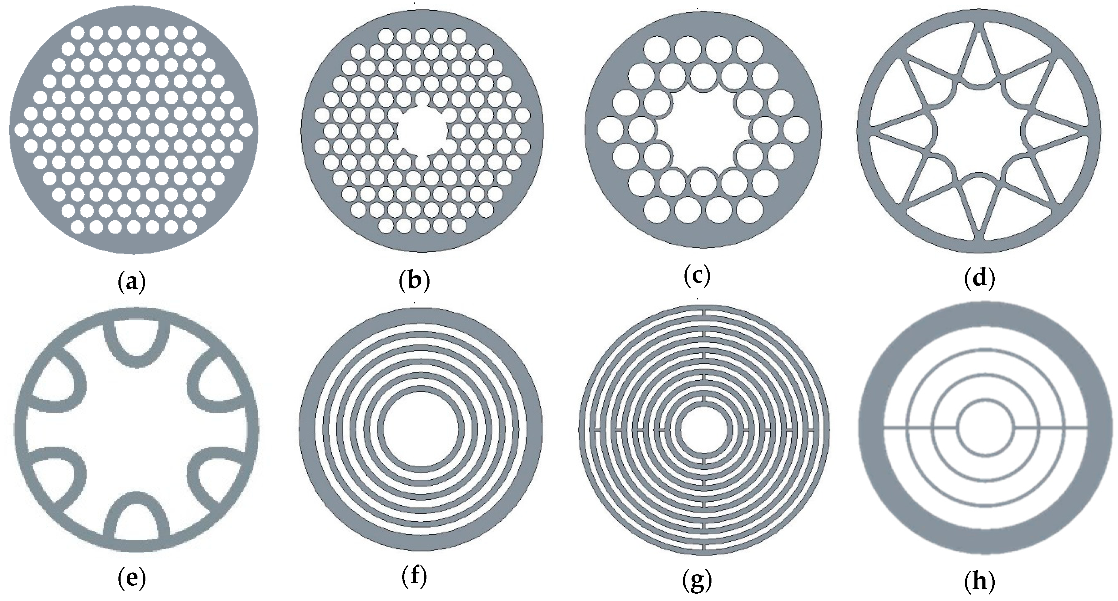
Figure 1. (a) Porous polymer terahertz fiber design [38] (b) First all-dielectric 3D printed terahertz waveguide [64]; (c) 3D printed terahertz waveguide based on Kagome photonic crystal structure [65]; (d) Hollow-core with negative curvature [67]; (e) 3D-printed polymer antiresonant waveguide [68]; (f) 3D printed terahertz Bragg [69]; (g) Bragg waveguide with defect layers [70]; (h) Single-mode Bragg waveguide [71].
Fibers 06 00043 g001
Figure 2. (a) Effective refractive index of ARROW A, ARROW B, and Bragg fiber; (b) Spectral transmission with high losses dips due to the resonant effect. The numerical simulations considered 1 m long fibers to the transmission analyses.
Fibers 06 00043 g002
Figure 3. (a) Experimental and numerical transmission of ARROW A (93 mm long); (b) Experimental and numerical transmission of the Bragg fiber (100 mm long). Inset the reference and sample electrical pulse.
Fibers 06 00043 g003
Table 1. Summarized fibers characteristics.
FiberGuiding MethodPrinting MethodMaterialLoss (dB/cm)Year
Figure 1bPhotonic BandgapPolyjetUV-resin0.3 @105 GHz2011 [64]
Figure 1cPhotonic BandgapPolyjetUV-resin0.08 @1 THz 2016 [65]
Figure 1dAntiresonant effectFDMABS0.3 @0.47 THz2015 [67]
Figure 1eAntiresonant effectFDMPC10 @0.3 THz2018 [68]
Figure 1fAntiresonant effectFDMABS0.1 @0.4 THz2015 [69]
Figure 1gBragg ReflectionSLAUV-resin0.65 @0.35 THz2017 [70]
Figure 1hBragg ReflectionSLAUV-resin0.03 @0.27 THz2018 [71]
Table 2. Parameters of the 3D printed fibers [67,69,73,74].
ParametersArrow A [67]Arrow B [73]Bragg [69]
Fibers 06 00043 i001 Fibers 06 00043 i002 Fibers 06 00043 i003
Dcore (mm)8.27.27.2
Dext (mm)551822.8
eh (mm)0.540.40.55
el (mm)--0.75
L (mm)679393
PolymerABSUV-resinABS
Material loss @1 THz78 dB/cm 47 dB/cm [74]78 dB/cm