Article

The Fiber Connection Method Using a Tapered Silica Fiber Tip for Microstructured Polymer Optical Fibers

1
INESC TEC and Department of Physics and Astronomy, Faculty of Sciences of University of Porto, Rua do Campo Alegre 687, 4169-007 Porto, Portugal
2
Wroclaw University of Science and Technology, Faculty of Fundamental Problems of Technology, Wybrzeze Wyspianskiego 27, 50-370 Wroclaw, Poland
3
Maria Curie-Sklodowska University, Laboratory of Optical Fibre Technology, Pl. M. Curie-Sklodowskiej 3, 20-031 Lublin, Poland
*
Author to whom correspondence should be addressed.
Fibers 2018, 6(1), 4; https://doi.org/10.3390/fib6010004
Submission received: 9 October 2017 / Revised: 2 January 2018 / Accepted: 4 January 2018 / Published: 9 January 2018
(This article belongs to the Special Issue Fabrication of Special Optical Glass and Polymer Fibres)

Abstract

:
In this work, an alternative method of coupling light into microstructured polymer fibers is presented. The solution consists in using a fiber taper fabricated with a CO2 laser. The connection is formed by inserting a tapered silica tip into the holes of a microstructured polymer fiber. This alternative method is duly characterized and the feasibility of such fiber connection to enable the polymer fiber as a displacement sensor is also demonstrated.

1. Introduction

The interest in using polymer optical fibers (POFs) for telecommunications [1,2] and sensors [3,4,5,6] has grown in the last several years. These POFs possess different characteristics from silica fibers, such as their elastic properties [7], which allow them to work in different environments.
POFs require different handling methods. In order to have a proper cut, the use of a hot blade [3] to cut the fiber, instead of commercially available fiber cleavers, is required.
Problems arise from the connectorization process of POFs. The connectorization process is seen as the best option. However, the core of the POFs are usually displaced from the center of the connector [8,9], compromising the efficiency of the technique. This is amplified by the concentricity of the core related to the fiber. Other connections can be made using a 3D translation platform together with matching gel [10] or by focusing the light using lenses [11].
Microstructured optical fibers (MOFs) have been distinguished from standard optical fibers for their single material composition and the presence of holes surrounding the core. Depending on the hole geometry, these fibers can achieve single-mode operation at all wavelengths [12]. Their single polymer composition allows for the use of low-loss materials and provides advantages in the fabrication process over standard POF and silica fibers [13,14].
Optical fiber tapers are optical fibers that have been heated up and stretched in order to create a thin filament with a very small diameter. The focused CO2 laser [15] and etching techniques [16,17,18,19], among other techniques for fabricating in-line tapers or tapered tips are available. Tapered and lensed fibers are good solutions for coupling light between optical fibers and waveguide devices, laser diodes, or photodiodes.
In this work, a fiber taper connection method for microstructured POFs (MPOFs) using silica fiber tapers is presented. A displacement sensor based on a “figure-eight” design was tested with the polymer fiber, determining the viability of this connection for sensing applications.

2. Materials and Methods

The MPOF used in this experiment is composed of poly (methyl methacrylate) (PMMA). A microscope image of the fiber is presented in Figure 1a. The fiber has an outer diameter with 215 µm, and a core diameter with 9 µm. The core is surrounded by a hexagonal shaped array of holes with a diameter, d, of 2.4 µm and with a separation between holes of 5.7 µm, Λ. The ratio value between d and Λ is 0.42, which corresponds to the limit region between single-mode operation and multimode operation. The fiber was fabricated in Maria Curie Sklodowska University using the preform drilling technique [14].
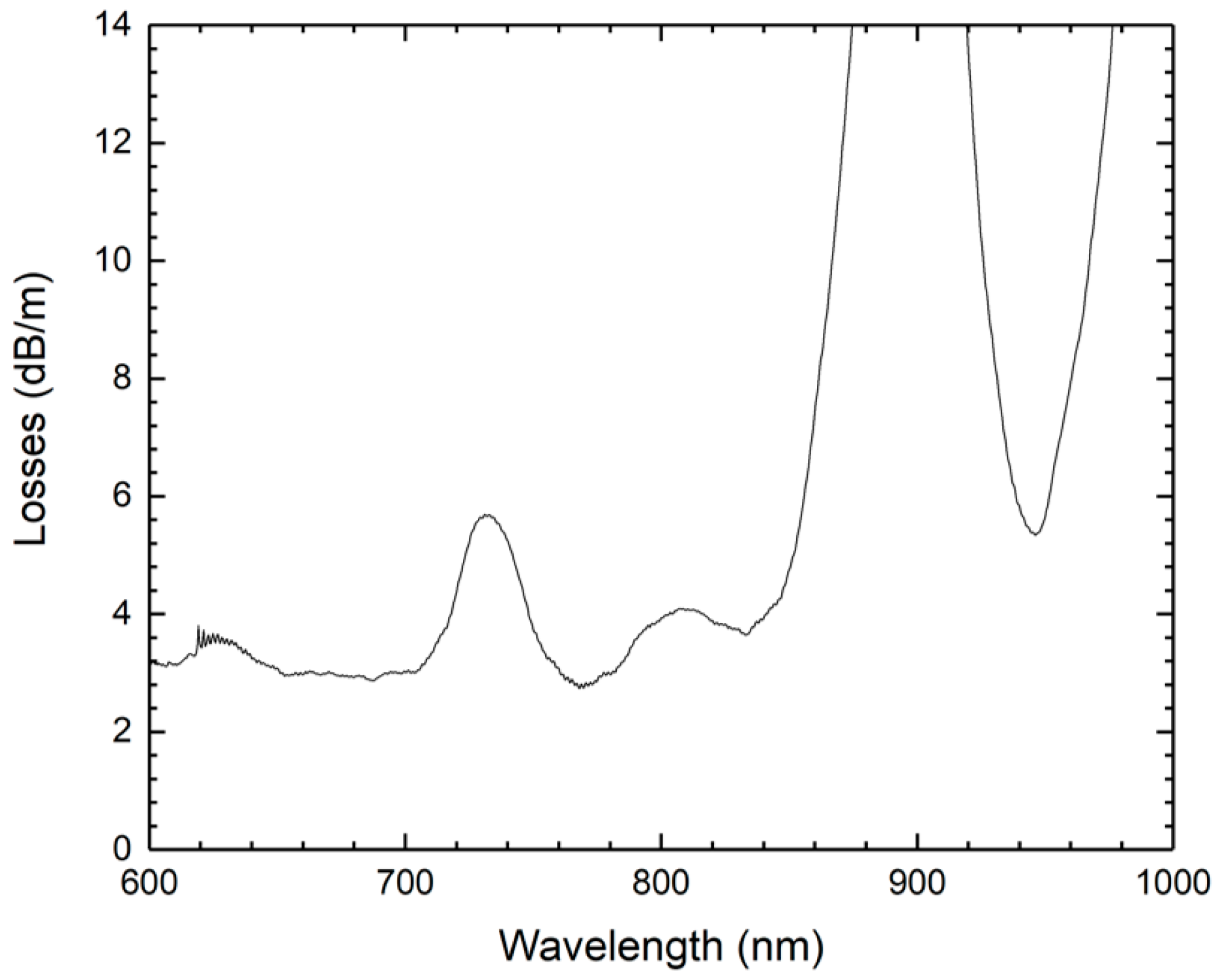
In order to determine if the fiber is single-mode or multimode, a mode analysis was performed using Comsol Multiphysics. The analysis was performed for two wavelengths: 600 nm and 1000 nm. For both wavelengths, only one mode could be propagated in the fiber, revealing that the MPOF is single-mode at 600 nm. The fundamental mode field distribution simulated for a wavelength of 600 nm is depicted in Figure 1b. The obtained effective refractive index of the fundamental mode is 1.4893 at 600 nm and 1.4831 at 1000 nm. The numerical aperture of the fiber was estimated to be around 0.1. Figure 2 presents the loss spectrum of the MPOF. The loss peak around 900 nm corresponds to light absorption by the PMMA [20].
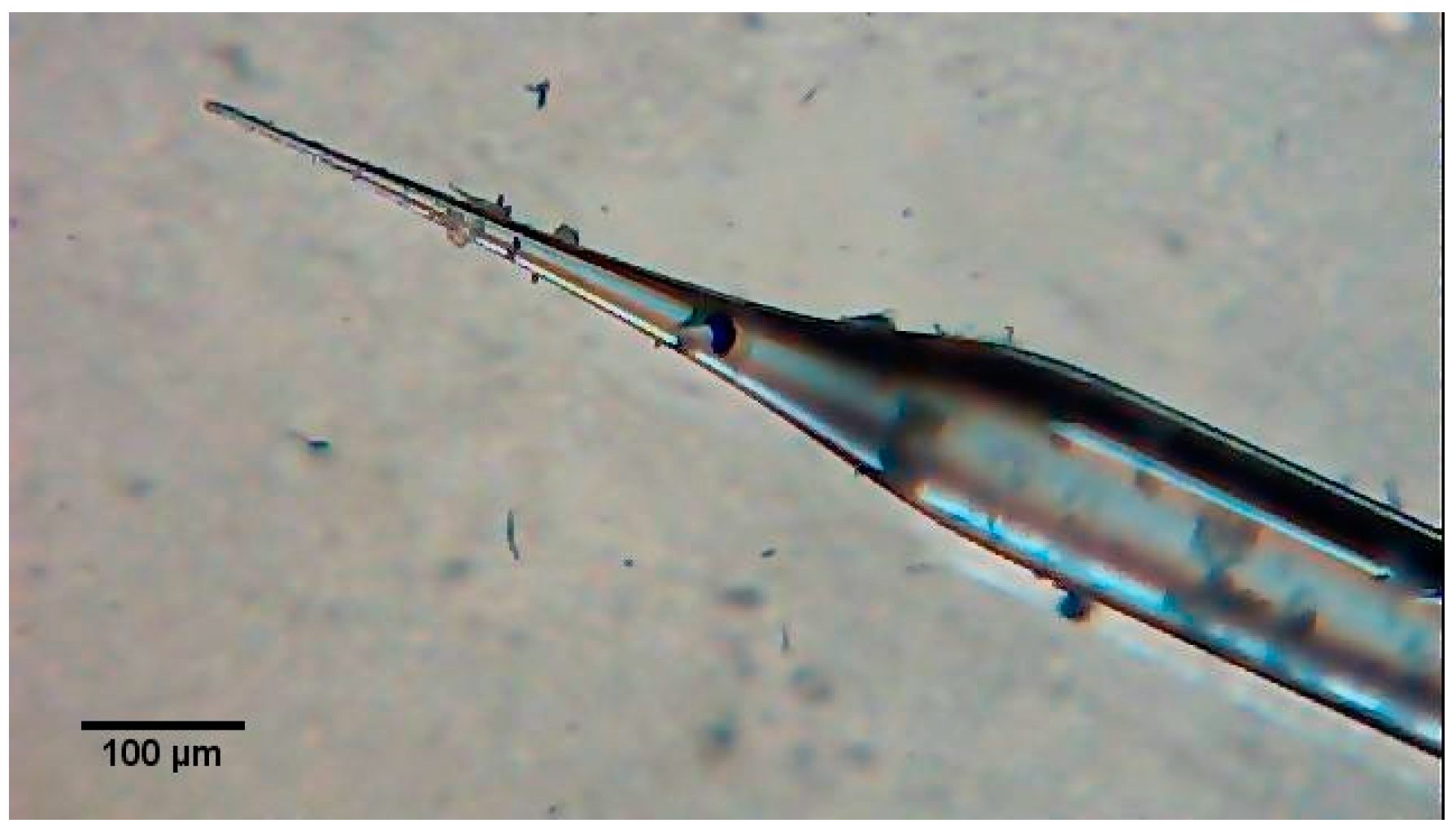
The fiber connection method for the proposed MPOF is based on a tapered fiber tip. The tapered tip used in the experiment was fabricated using a CO2 laser technique [16,17,18,19]. The CO2 laser is focused on the silica fiber, while the fiber is stretched with programmed moving platforms. The process decreases the diameter of the fiber forming a taper and eventually breaking it, creating a tapered tip. A micrograph of a CO2 laser fabricated tapered fiber tip is shown in Figure 3. Several fiber tapers were fabricated with different diameters and tested as fiber connectors. In this experiment, the optimized taper was ~5 µm in diameter (tip) and ~250 µm in length (taper waist).

3. Results

3.1. Connection

The fiber connection was made manually using the translation stage of a splice machine. No electric arc was used to form the connection, and the electrodes were removed to avoid destroying the MPOF with a discharge. The tapered tip was inserted into the MPOF holes, creating the connection, as seen in Figure 4a. Figure 4b shows the connection using a rough alignment near the core by means of an He–Ne laser source. Due to the elastic properties of the MPOF, the silica tapered tip can be easily inserted inside the MPOF without breaking it. The taper was placed inside the hole, close to the core, to ensure a good coupling between the taper and the polymeric fiber. However, high losses are expected due to the divergence angle at the tip and the off-axis coupling. It was observed that the hole was damaged if the fiber tips had diameters higher than the size of the holes. However, it does not affect the losses in the polymer fiber when it is illuminated by the taper.
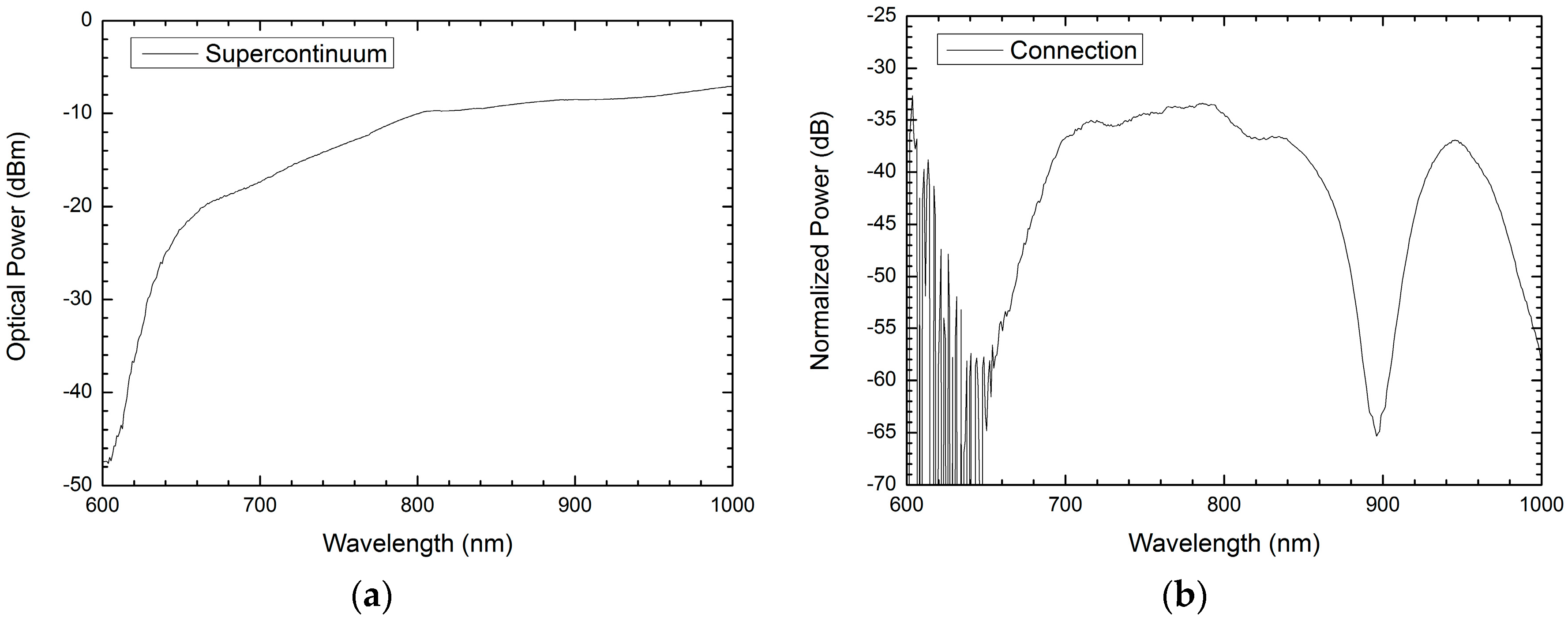
The first tests were performed using an He–Ne laser as a light source (see Figure 4b) in order to ensure coupling of light into the MPOF. The light source was then changed to a supercontinuum source to obtain the spectral behavior of the connection. The output spectrum was acquired using an optical spectrum analyzer (OSA). Figure 5a presents the transmission spectrum of the supercontinuum source before connecting the polymer fiber. Figure 5b shows the transmission spectrum of a fiber taper tip connection to a 1 m polymer fiber, normalized to the source spectrum of Figure 5a. The MPOF was connected to the OSA with a commercial connector that allowed enough precision to insert light into the device. Since the MPOF is single-mode in the wavelength range of this experiment, light injected in the fiber can only excite the fundamental mode of the MPOF core. However, some light is also coupled into the outer part of the MPOF, being lost to the outside medium. The fiber connection losses and propagation losses of the MPOF were found to be 34 dB at 750 nm and 37 dB at 950 nm, respectively. The drop at 900 nm is due to propagation losses caused by the absorption of the PMMA, as previously discussed. Although losses are higher compared to other conventional connections (1–9 dB) [21], it was observed that the proposed fiber connection is very stable and easy to achieve, avoiding the use of complex 3D alignment setups, index-matching gel, or the need for polishing to improve the connection.

3.2. Displacement Test

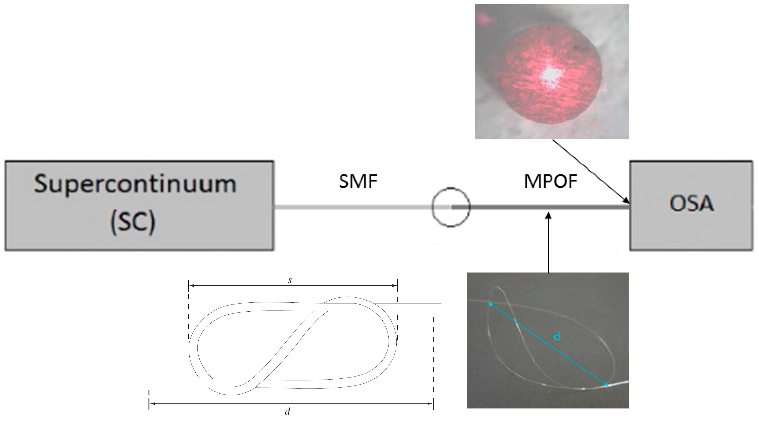
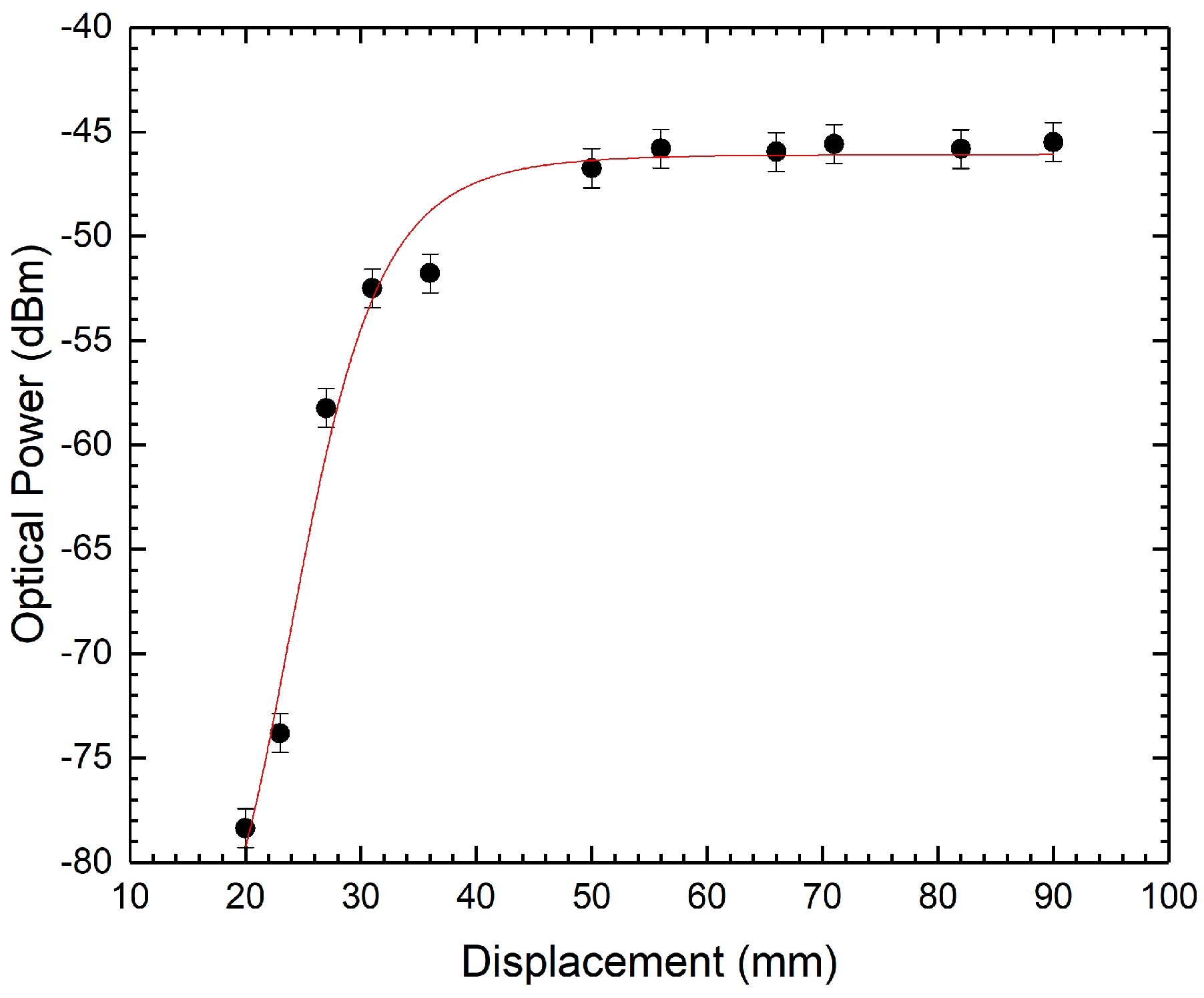
The MPOF was characterized as a displacement sensor while using the fiber tip connection. Figure 6 presents the setup used in the characterization. A “figure-eight” sensor was created for displacement, d, measurements, as defined in Figure 6. Figure 6 also illustrates the sensing head mechanism. When a displacement in the d length occurs, the sensing head size s decreases and power loss is induced through the decrease of the loop radius. The sensor does not require an external mechanism to increase or decrease the bend radius. With the decrease in the displacement, the power of the transmitted signal drops. By tracking the power of the maximum near the 950 nm as a function of the displacement, the sensor was characterized. The output power as a function of the displacement d is depicted in Figure 7. The sensor shows a very small sensitivity above 40 mm, but a higher sensitivity below 32 mm, namely 2.5 dBm/mm with a resolution of 0.4 mm. This proves that the fiber connection can be used while the sensors are characterized.

4. Discussion

An alternative light coupling method for MPOFs was demonstrated. Light transmission was achieved by inserting a tapered silica fiber tip into the holes of an MPOF with a rough alignment. The connection has proven to have the capacity of being used in practical setups. The capacity and viability of the connection to enable sensing measurements while using an MPOF as a displacement sensor was demonstrate. Future work will be focused on decreasing the connection losses. Additionally, studying new geometries of the tapered tip could ensure an improved connection.

Acknowledgments

This work was supported by Project CORAL–Sustainable Ocean Exploitation: Tools and Sensors, NORTE-01-0145-FEDER-000036, financed by the North Portugal Regional Operational Programme (NORTE 2020), under the PORTUGAL 2020 Partnership Agreement, and through the European Regional Development Fund (ERDF).

Author Contributions

Orlando Frazão conceived and designed the experiments; Miguel Ferreira performed the experiments; Miguel Ferreira and Orlando Frazão analyzed the data; André Gomes developed the fiber tips and performed the simulations; Dominik Kowal, Gabriela Statkiewicz-Barabach, and Pawel Mergo contributed the MPOF; Miguel Ferreira wrote the paper.

Conflicts of Interest

The authors declare no conflict of interest. The founding sponsors had no role in the design of the study; in the collection, analyses, or interpretation of data; in the writing of the manuscript; or in the decision to publish the results.

References

  1. Koike, Y.; Ishigure, T.; Nihei, E. High-bandwidth graded-index polymer optical fibre. Polymer 1991, 32, 1737–1745. [Google Scholar] [CrossRef]
  2. Ishigure, T.; Nihei, E.; Koike, Y. Graded-index polymer optical fiber for high-speed data communication. Appl. Opt. 1994, 33, 4261–4266. [Google Scholar] [CrossRef] [PubMed]
  3. Chen, X.F.; Zhang, C.; Webb, D.J.; Peng, G.-D.; Kalli, K. Bragg grating in polymer optical fibre for strain, bend and temperature sensing. Meas. Sci. Technol. 2010, 21, 94005. [Google Scholar] [CrossRef]
  4. Johnson, I.P.; Webb, D.J.; Kalli, K. Hydrostatic pressure sensing using a polymer optical fibre Bragg gratings. In Proceedings of the Asia Pacific Optical Sensors Conference, Chengdu, China, 31 January–3 February 2012; Volume 8351, pp. 835106–835107. [Google Scholar]
  5. Ferreira, M.F.S.; Statkiewicz-Barabach, G.; Kowal, D.; Mergo, P.; Urbanczyk, W.; Frazão, O. Fabry-Perot cavity based on polymer FBG as refractive index sensor. Opt. Commun. 2017, 394, 37–40. [Google Scholar] [CrossRef]
  6. Jensen, J.; Hoiby, P.; Emiliyanov, G.; Bang, O.; Pedersen, L.; Bjarklev, A. Selective detection of antibodies in microstructured polymer optical fibers. Opt. Express 2005, 13, 5883–5889. [Google Scholar] [CrossRef] [PubMed]
  7. Yang, D.X.; Yu, J.; Tao, X.; Tam, H. Structural and mechanical properties of polymeric optical fiber. Mater. Sci. Eng. A 2004, 364, 256–259. [Google Scholar] [CrossRef]
  8. Abang, A.; Webb, D.J. Demountable connection for polymer optical fiber grating sensors. Opt. Eng. 2012, 51, 80503. [Google Scholar] [CrossRef]
  9. Abang, A.; Saez-Rodriguez, D.; Nielsen, K.; Bang, O.; Webb, D.J. Connectorisation of fibre Bragg grating sensors recorded in microstructured polymer optical fibre. In Proceedings of the Fifth European Workshop on Optical Fibre Sensors, Krakow, Poland, 19–22 May 2013; Volume 8794, p. 87943Q. [Google Scholar]
  10. Chen, X.; Zhang, C.; Webb, D.J.; Kalli, K.; Peng, G.D. Highly sensitive bend sensor based on bragg grating in eccentric core polymer fiber. IEEE Photonics Technol. Lett. 2010, 22, 850–852. [Google Scholar] [CrossRef]
  11. Durana, G.; Gómez, J.; Aldabaldetreku, G.; Zubia, J.; Montero, A.; De Ocáriz, I.S. Assessment of an LPG mPOF for strain sensing. IEEE Sens. J. 2012, 12, 2668–2673. [Google Scholar] [CrossRef]
  12. Birks, T.A.; Knight, J.C.; Russell, P.S. Endlessly single-mode photonic crystal fiber. Opt. Lett. 1997, 22, 961–963. [Google Scholar] [CrossRef] [PubMed]
  13. Large, M.C.J.; Van Eijkelenborg, M.A.; Argyros, A.; Zagari, J.; Manos, S.; Issa, N.A.; Bassett, I.; Fleming, S.; Mcphedran, R.C.; De, C.M.; et al. Microstructured polymer optical fibers: Progress and promise. In Proceedings of the International Symposium on Biomedical Optics, San Jose, CA, USA, 19–25 January 2002; Volume 4616, pp. 105–116. [Google Scholar]
  14. Barton, G.; Van Eijkelenborg, M.A.; Henry, G.; Large, M.C.J.; Zagari, J. Fabrication of microstructured polymer optical fibres. Opt. Fiber Technol. 2004, 10, 325–335. [Google Scholar] [CrossRef]
  15. Gomes, A.D.; Frazão, O. Mach-Zehnder Based on Large Knot Fiber Resonator for Refractive Index Measurement. IEEE Photonics Technol. Lett. 2016, 28, 1279–1281. [Google Scholar] [CrossRef]
  16. Tao, M.; Jin, Y.; Gu, N.; Huang, L. A method to control the fabrication of etched optical fiber probes with nanometric tips. J. Opt. 2009, 12, 15503. [Google Scholar] [CrossRef]
  17. Nikbakht, H.; Latifi, H.; Amini, T.; Chenari, Z. Controlling cone angle of the tapered tip fiber using dynamic etching. In Proceedings of the 23rd International Conference on Optical Fiber Sensors, Santander, Spain, 2–6 June 2014; Volume 9157, p. 91574Q. [Google Scholar] [CrossRef]
  18. Haber, L.H.; Schaller, R.D.; Johnson, J.C.; Saykally, R.J. Shape control of near-field probes using dynamic meniscus etching. J. Microsc. 2004, 214, 27–35. [Google Scholar] [CrossRef] [PubMed]
  19. Barucci, A.; Cosi, F.; Giannetti, A.; Pelli, S.; Griffini, D.; Insinna, M.; Salvadori, S.; Tiribilli, B.; Righini, G.C. Optical fibre nanotips fabricated by a dynamic chemical etching for sensing applications. J. Appl. Phys. 2015, 117. [Google Scholar] [CrossRef]
  20. Hornak, L.A. Polymers for Lightwave and Integrated Optics: Technology and Applications; CRC Press: New York, NY, USA, 1992. [Google Scholar]
  21. Oliveira, R. Novel Techniques and Devices for Optical Communications and Sensing Technologies; University of Aveiro: Aveiro, Portugal, 2017. [Google Scholar]
Figure 1. (a) Scanning electron microscope picture of an microstructured polymer optical fiber (MPOF); (b) Simulated fundamental mode field distribution for the MPOF at 600 nm.
Fibers 06 00004 g001
Figure 2. The loss spectrum of the microstructured polymer optical fiber.
Fibers 06 00004 g002
Figure 3. Microscope image of the tapered fiber tip.
Fibers 06 00004 g003
Figure 4. Photo of the tapered tip inside of the MPOF (a) with no light source and (b) with an He–Ne laser source.
Fibers 06 00004 g004
Figure 5. (a) Supercontinuum source spectrum and (b) normalized transmission spectrum using the fiber taper tip connection.
Fibers 06 00004 g005
Figure 6. Experimental setup with the sensing head mechanism. SC: Supercontinuum; SMF: single mode fiber; OSA: optical spectrum analyser.
Fibers 06 00004 g006
Figure 7. Output power as a function of the displacement d.
Fibers 06 00004 g007