Abstract
In this work, core–shell electrospinning was employed as a simple method for the fabrication of composite coaxial polymer fibers that became hollow ceramic tubes when calcined at high temperature. The shell polymer solution consisted of polyvinyl pyrollidone (PVP) in ethanol mixed with an aluminum acetate solution to act as a ceramic precursor. The core polymer was recycled polystyrene to act as a sacrificial polymer that burned off during calcination. The resulting fibers were analyzed with X-ray diffraction (XRD) and energy dispersive spectroscopy (EDS) to confirm the presence of gamma-phase aluminum oxide when heated at temperatures above 700 °C. The fiber diameter decreased from 987 ± 19 nm to 382 ± 152 nm after the calcination process due to the polymer material being burned off. The wall thickness of these fibers is estimated to be 100 nm.
1. Introduction
Aluminum oxide is a versatile material that is easy to produce in micro-, submicro-, and nanometer-diameter sizes by electrospinning. The fabrication of nanostructured ceramics is commonly done using a polymer template of the desired nanostructure containing the ceramic metal salts in the polymer. In electrospinning, a polymer jet is launched from an electrically charged spinneret. As the jet passes through the electric field in the air the jet stretches and elongates to a very small diameter and the solvent evaporates to solidify the polymer before it collects on a grounded collector [1]. A typical single capillary electrospinning setup is diagrammed in Figure 1.
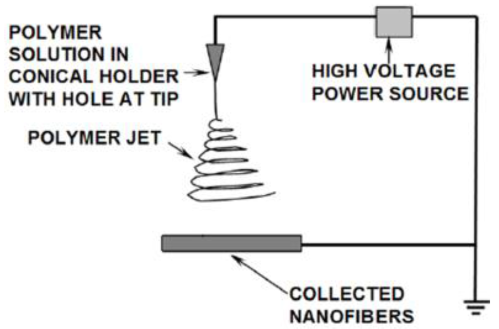
Figure 1.
Electrospinning illustration.
The collected fibers form a non-woven mat with a similar appearance to a sheet of paper. This method produces fibers with a size distribution typically ranging from a few tens of nanometers to a few microns. In some instances the method can fabricate individual fibers less than 10 nm in diameter [2]. The mat can be placed in a furnace in air to burn off the polymer portion of the fibers and allow oxygen to react with the metal salts to form ceramic metal oxide fibers [3]. Several types of metal oxides can be produced by this method [4]. Aluminum oxide was chosen for this work because it is relatively easy to electrospun from several polymers [5] and due to its beneficial properties to several applications.
By changing the nozzle design a two-polymer coaxial jet can be electrospun having one polymer mixture (the core) within another polymer mixture (the shell), thus producing electrospun core–shell fibers. The electrospun core–shell fibers are arbitrarily long, and much longer than core–shell fibers that are produced by other methods such as template based approaches [6]. Coaxial spinning works best with immiscible core and shell polymer solutions, to ensure there is no mixing between the phases, and can be done using two solutions in a single nozzle system [7]. However, due to the rapid solvent evaporation and fiber collection during the electrospinning process, it can be also done with miscible solutions [8]. The core–shell electrospinning process can be used for a wide variety of applications, including making conductive nanowires [9], composite polymer fibers [10], hollow fibers [11] and to encase a liquid inside of a polymer fiber, which could be useful in timed release drug delivery [12]. Liu also has results showing that a single capillary electrospinning is capable of producing hollow ceramic fibers with one solution, due to the proposed mechanism of the Kirkendall effect [13,14], which can reduce the need for specialized equipment or additional steps for fabricating hollow fibers [15]. Cheng has demonstrated the fabrication of hollow ceramic tin oxide fibers from one solution single capillary electrospinning with high heating rates of the furnace during calcination (10 °C/min) [16,17].
By using a core–shell electrospinning device, a composite polymeric fiber can be spun with a coaxial configuration with different materials in the core and shell of the fiber. In this case, the core material was a sacrificial polymer that was burned off during the calcination process to leave behind a hollow ceramic tube. The flow rates of the core and shell solutions were controlled by separate syringe pumps to allow control of the wall thickness of the shell material around the core. The custom made electrospinning device used in this work allows for more control of the process parameters while maintaining a simple and easy to clean method for the fabrication of core–shell and hollow fibers. The benefit of using a sacrificial polymer in the core over mineral oil, which is commonly used by others carrying out electrospinning of hollow fibers [6,11,18,19,20], is that the mineral oil was more difficult to use in our experience and our method removed the step of extracting out the oil prior to calcination. This method also removed the deposition steps from Katoch’s work, where the sacrificial polymer was spun first and the ceramic tube wall was deposited in later steps before removing the core [21], allowing the sacrificial core polymer to be spun along with the ceramic material that will make the hollow tube wall.
2. Experimental Section
2.1. Materials
Core–shell fibers require the core material to differ from the shell material. In this work the shell material was formed of alumina from a template polymer, Polyvinylpyrrolidone (PVP), and the core material was polystyrene (PS). This combination of shell and core materials allowed the two phases to exist during the spinning process to produce composite fibers. PVP, aluminum acetate, chloroform, formic acid and ethanol were purchased from Sigma-Aldrich (St. Louis, MO, USA). The water used in this work was deionized on site via an ion exchange resin system purchased locally through Culligan (Rochester, NY, USA). The PS was obtained by recycling Styrofoam coffee cups.
2.2. Solution Preparation
For the shell material, the aluminum oxide was produced from a ceramic precursor mixture consisting of 2.22 g aluminum acetate dissolved in 5.56 g water and 2.22 g formic acid. The solution formed a clear and fully dissolved solution after mixing 24 h at 40 °C. This ceramic precursor solution was combined with a polymer solution of 2 g PVP dissolved in 8 g ethanol. The combined solution was mixed for at least 2 h to ensure it is well mixed prior to electrospinning. The core material was recycled PS dissolved in chloroform at 1.5 g of polymer in 8.5 g of solvent.
2.3. Core–Shell Electrospinning Process
The prepared electrospinning solutions were loaded into 5 cc syringes and delivered to a spinneret via a syringe pumps (World Precision Instruments, SP101i, Sarasota, FL, USA) and Teflon tubes. The polymer solution flow rates to the spinneret were set at 12 µL per minute and adjusted as needed to achieve the desired coaxial jet flow. The spinneret was electrically charged to a potential of 20 kV. The gap distance between the spinneret to the grounded collector was 14 cm. Soon after the spinning is started, a fiber mat was observed on the collector. The thickness of the fiber mat was controlled by the duration of the spinning process.
As seen in Figure 2, a custom made device for co-axial electrospinning was designed and fabricated by using two polyvinylidene fluoride plates with stainless steel tubes and compression fittings. The two plates were bolted to prevent leakage.
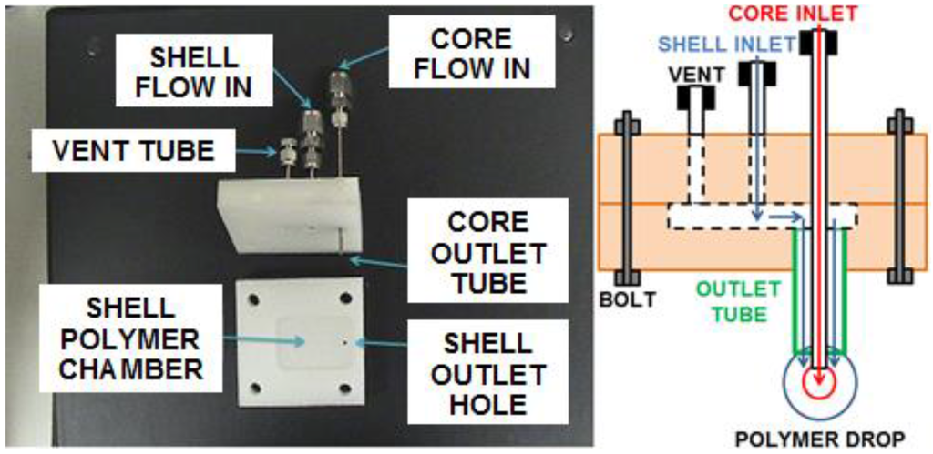
Figure 2.
Photograph and schematic of the core–shell electrospinning device.
The two plates were 6.2 cm × 6.2 cm and 1.3 cm thick. The top plate was drilled with 6.35 mm (1/4 inch) holes to snugly fit a 1/16 inch NPT tap for compression fittings for the vent, shell inlet, and core inlet stainless steel tubes with 1.59 mm (1/16 inch) outside diameters. The core inlet tube had an inside diameter of 0.57 mm to approximate a 21 gauge needle previously used to electrospin. The shell inlet and vent tubes had a larger inside diameter of 1.33 mm for ease of loading the polymer solution. The vent and shell inlet tubes extended to bottom edge of the top plate and opened to a recessed chamber machined into the bottom plate. The chamber had a 3.18 mm (1/8 inch) outlet hole directly under the core inlet tube. The outlet hole was fitted with a stainless steel outlet tube with outside diameter 3.18 mm (1/8 inch) and an inside diameter of 2.41 mm that extended 2 cm below the bottom surface of the bottom plate. The core inlet tube extended through the top plate, through the shell material chamber, to the bottom opening of the outlet tube. The three tubes were fitted with compression fittings (Swagelok, Cleveland, OH, USA) to attach a plug (for the vent) and flexible PTFE tubes for delivery of the core and shell polymer solutions from the syringe pumps.
The shell material was pushed into the chamber until it completely filled the chamber and started coming out of the vent tube, which was then capped. The core material was pumped through the core inlet tube and the shell material was simultaneously pumped through the chamber and through the annular space between the outlet tube and the core inlet tube. This caused the flow of both polymers to form a drop at the end of the outlet tube that had the core material inside of the shell material. The outlet tube was electrically charged to a high voltage that caused a jet of both materials to launch from the drop. Figure 3 shows the setup with the two syringe pumps, the nozzle device and the grounded collector.
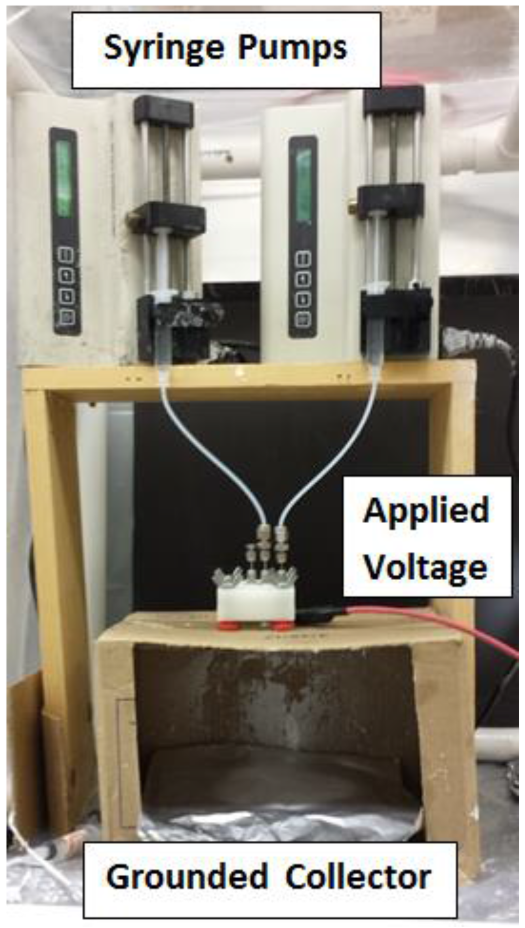
Figure 3.
Core–Shell electrospinning process.
2.4. Calcination of Polymer Fibers
The electrospun fiber mat was rolled into a cylindrical shape and calcined by heating the mat in air. The cylindrical shape was chosen for its convenience of placing the mat inside of a tubular holder for a subsequent application. The rolled mat was placed in a vacuum oven at ambient temperature and a few hundred kPa vacuum pressure applied to evaporate any residual solvents. The dried rolled fiber mat was placed in a furnace in air at 600 °C to 800 °C to burn off the polymer material and allow the oxygen in the atmosphere to react with the aluminum in the aluminum acetate to form aluminum oxide. As the metal oxide grains formed, the ceramic material retained the fibrous structure of the template polymer fiber mat. The core PS material was burned off, and since it did not contain the aluminum acetate precursor, the center of the fibers occupied by the PS formed a hollow core within the alumina shell material, as can be seen Figure 4.
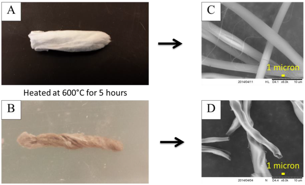
Figure 4.
Rolled fiber bundle (A) before and (B) after calcination at 600 °C for 5 h and SEM images (C) before and (D) after to show the change in fiber structure. Image (D) shows the ends of several of the fibers and the hollow cores are visible.
2.5. Characterization
SEM images were taken on a Hitachi TM-3000 electron microscope (Hitachi, Tokyo, Japan) to observe the fiber and mat structures. Higher resolution images were obtained on a Field Emission Scanning Electron Microscopy (FE-SEM, JSM-7401F JEOL Ltd., Tokyo, Japan) to better observe the hollow interior of the fibers. An X-ray diffractometer with Cu anode (Kα1 = 0.154056 nm) (Bruker AXS Dimension D8 X-Ray System, Bruker Corporation, Billerica, MA, USA) was used to determine the crystal structure of the Al2O3 fibers. The voltage was set to 40 kV and the current was set to 40 mA. The crystallite size of the alumina fibers was estimated using the Scherrer equation, which relates the full width at half maxima (FWHM), W, of the most intense peak (440) of γ-Al2O3 fiber to the angle of incidence, θ, via S = cλ/Wcosθ. The percent crystallinity of fibers was calculated using the Segal equation, which uses the ratio of the most intense peak (440) from the crystalline peaks to the sum of the crystalline and amorphous intensities, XCR = I(440)/(I(440) + I(amorph)) [22]. To control the crystal structure of the aluminum oxide material, the calcination temperature was modified, as described in the Results and Discussion section.
3. Results and Discussion
3.1. Fiber Size Analysis
The SEM images were analyzed using FibraQuant™ 1.3 software (nanoScaffold Technologies. LLC, Chapel Hill, NC, USA) to determine a fiber size distribution of the materials produced. Solid polymer fibers (not calcined) of only PVP and only PS were electrospun, and core–shell fibers of PS and PVP were electrospun, under similar electrospinning conditions, for comparison purposes. The average fiber size of the solid PVP and solid PS fibers were 408 ± 99 nm and 2.92 ± 0.91 μm respectively. The core–shell electrospun polymer fibers of these two materials had an average size of 987 ± 19 nm. The ± values represent one standard deviation of the fiber size distributions. Fiber size distributions and images of these fibers are in Figure 5.
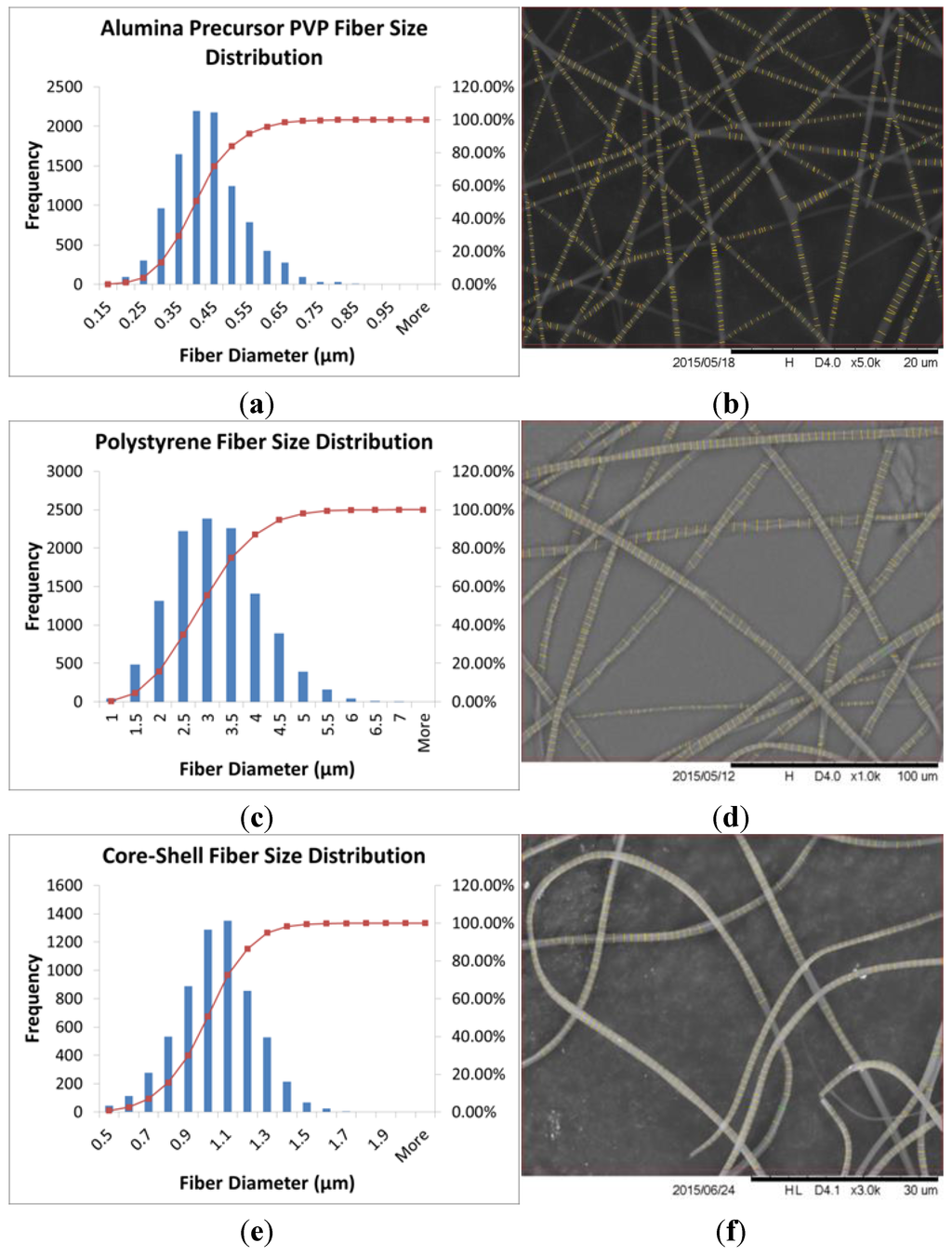
Figure 5.
Fiber size distribution analysis histograms and sample SEM images after FibraQuant™ analysis for (a,b) alumina precursor PVP; (c,d) polystyrene; and (e,f) core–shell electrospun fibers. The FibraQuant™ software inserted the fine lines at the measurement points onto the fibers in the images in (b,d,f). The fiber size distributions in (a,c,e) were measured from at least five separate SEM images of fibers with over 500 collective measurement points for each fiber material.
The PVP fibers were much smaller in diameter than the PS fibers when spun individually, but when the two materials were spun together, the fibers ended up being an intermediate size. This is due to the rapid evaporation rate of the chloroform as the solvent for the PS fibers, which limits the amount the fiber can stretch during the electrospinning process. When used as the core solution, the chloroform was the interior solvent, which slowed the evaporation rate of the solution. As expected, the fiber size of the co-axial fibers was larger than the PVP solid fiber spun alone, due to the presence of the PS polymer in the center of the fiber. After calcination of the core–shell polymer fibers, the average fiber size was 382 ± 152 nm. The distribution and SEM image is shown in Figure 6.
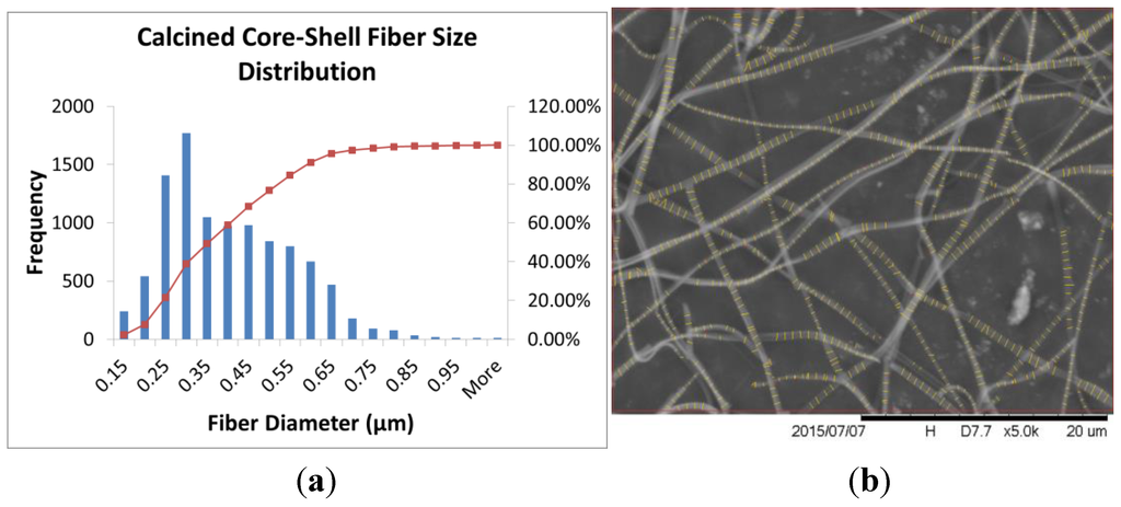
Figure 6.
(a) Fiber size distribution analysis histograms and (b) sample SEM images after FibraQuant™ analysis for the core–shell fibers after calcination at 600 °C for 5 h.
As expected, the fiber size was decreased after calcination due to the polymer material in the core and the shell being burned away.
3.2. XRD Analysis of Aluminum Oxide Structure
In Figure 7, the XRD patterns of the alumina ceramic fibers calcined at 600 °C shows that these fibers are amorphous in structure. As the thermal treatments progressed to 800 °C, γ-Al2O3 phase fibers were observed at 700 °C and 800 °C. Crystalline planes corresponding peaks of γ-Al2O3 fibers could be indexed. These samples indicate major peaks at 2θ values of 32.65°, 37.59°, 39.66°, 45.98°, 61.01°, and 67.07°, which correspond to γ-Al2O3 (220), (311), (222), (400), (511), and (440) crystal plane, respectively [23,24], as indicated in Figure 7.
During the calcination process, phase transformation started from amorphous to gamma phase, and the crystallinity of the samples was also increased from 13.2% (700 °C) to 40.6% (800 °C). The estimated γ-Al2O3 crystallite size was 8 nm.
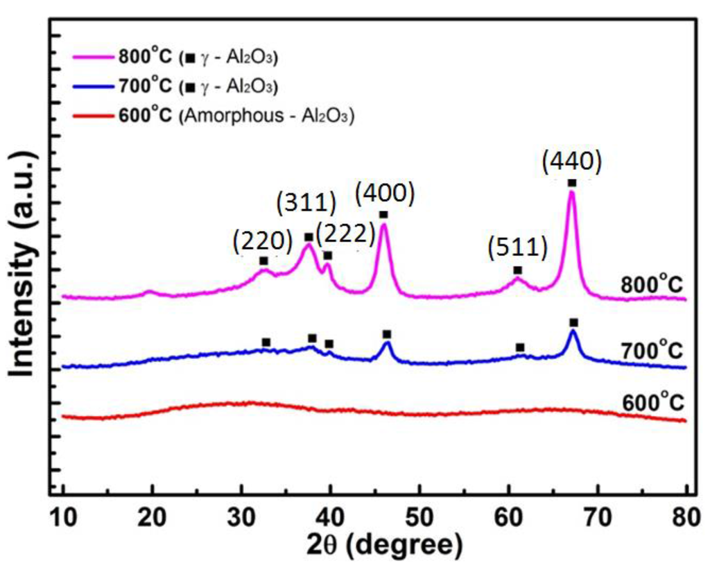
Figure 7.
X-ray diffraction peaks of alumina fibers calcined at 600 °C, 700 °C, and 800 °C.
3.3. EDS Analysis of Aluminum Oxide Composition
The SEM used is equipped with a Bruker Quantax 70 energy dispersive X-ray spectroscopy (EDS, Bruker Corporation, Billerica, MA, USA) system to analyze the atomic composition of a sample. The results of this analysis can be seen in Figure 8.
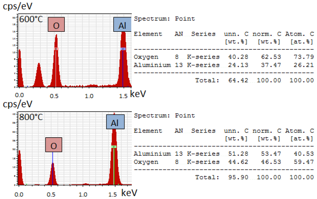
Figure 8.
EDS analysis of aluminum oxide fibers calcined at (top) 600 °C and (bottom) 800 °C.
Both the material calcined at 600 °C and 800 °C show strong aluminum and oxygen peaks, but the ratio of the aluminum to oxygen is closer to the 2:3 atomic ratio expected with aluminum oxide. The extra peak in the 600°C analysis is from carbon, which was from the carbon tape substrate used to attach the samples to the stage. As discussed in the XRD results, the material calcined at 600 °C is amorphous and transitions to the crystalline gamma phase when heated to beyond 700 °C, which can explain the differences in atomic percentages in this EDS analysis.
3.4. SEM Analysis of Hollow Fiber Structure
The hollow interior of the alumina fibers in Figure 9 were imaged using the FE-SEM. A low accelerating voltage of 5 kV and stable high vacuum of 9.63 × 10⁻⁵ Pa was used. LEI mode (Lower Secondary Electron Imaging mode) was used to image surface morphology of fibers at high magnification, which gives enhanced surface textural information. The samples were silver coated for 90 s using Denton vacuum model DESKII coating device.
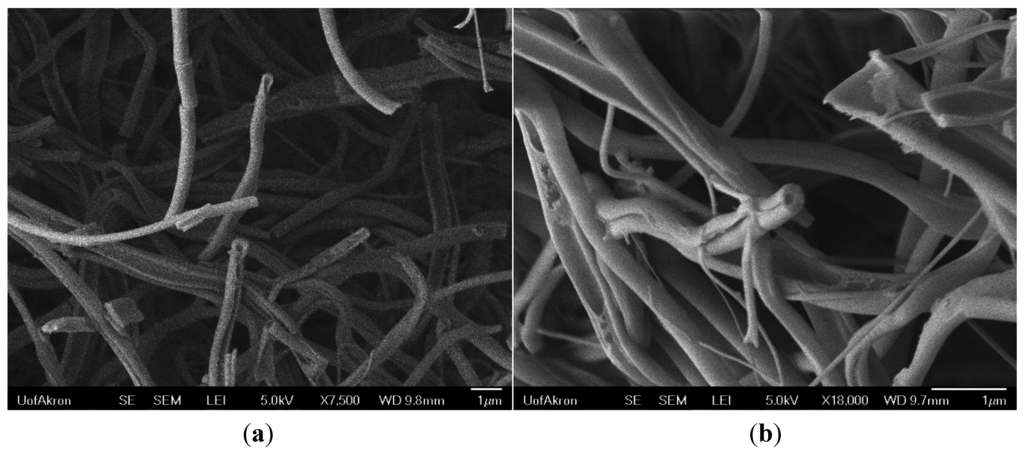
Figure 9.
High resolution FE-SEM images showing the hollow fiber structure at (a) 7,500×; and (b) 18,000× magnification.
The fibers in the above images demonstrate the hollow structure of the fibers after calcination at 800 °C for 5 h. The fibers were broken off of a similar bundle to the one shown in Figure 4, which explains the broken fibers. Otherwise, the fibers fabricated by this method are continuous, as seen in Figure 5 and Figure 6. The thicknesses of the shell walls are difficult to measure, but can be estimated from images such as those in Figure 4D and Figure 9. Here the wall thicknesses were about 100 nm.
4. Conclusions
Core–shell fibers were successfully fabricated by a co-axial electrospinning process. Due to solvent evaporation rates of the core and shell solutions being different, the fiber size of a composite alumina precursor PVP and polystyrene fiber (987 ± 19 nm) is greater than that of the precursor fibers on its own (408 ± 99 nm) but less than polystyrene on its own (2.92 ± 0.91 μm). The immiscibility of the shell and core solutions helped with the phase separation in the fibers. These fibers were converted to aluminum oxide after calcination. During calcination the shell precursor polymer reacted to form the ceramic tube wall and the core polystyrene material was burned away. After calcination, the size of the aluminum oxide fibers was significantly lower than the polymer core–shell fibers, at 382 ± 152 nm, due to the polymer material being burned away. X-ray diffraction confirmed the formation of γ-Al2O3 phase fibers at calcination temperatures greater than 700 °C.
Materials such as these can be used in a number of applications [25]. For example, they could be used for controlled diffusion of chemicals from the interior of the fibers. If the diffusion rate of a chemical through alumina is known, then by modifying the wall thickness one could control the diffusion rate of the chemical out of the hollow fiber interiors. Small micron sized alumina tubes could be used for metering and controlling liquid flows in microfluidic processes [26]. Previous work in our research group has used ceramic fibers as a catalyst support structure [27,28], and hollow fibers have been shown to have a higher surface area when compared to solid fibers [18], which can of benefit to improve performance of supported catalysts. Other applications may include filtration media and membranes on a smaller scale than other alumina tube membranes [29,30] to take advantage of the increased surface area from electrospun fibers. The calcination temperature and ramping rate can be used to control the crystal grain size and structure [31]. This could be used to modify the pore size and structure of the tube walls as the membrane for separations.
Acknowledgments
The authors thank the Coalescence Filtration Nanofiber Consortium (CFNC) for financial assistance and advice for this work. The authors would also like to thank Frank Pelc for his assistance and technical support in fabricating and maintaining the equipment used in this work.
Author Contributions
Jonathan W. Rajala designed and constructed the core-shell electrospinning apparatus, fabricated the fibers and carried out the SEM/fiber size analysis. Hyeon Ung Shin carried out the XRD characterization and analysis. Dinesh Lolla contributed the Field Emission Scanning Electron Microscopy imaging. George G. Chase advised the work.
Conflicts of Interest
The authors declare no conflict of interest.
References
- Reneker, D.H.; Yarin, A.L.; Fong, H.; Koombhongse, S. Bending instability of electrically charged liquid jets of polymer solutions in electrospinning. J. Appl. Phys. 2000, 87, 4531–4547. [Google Scholar]
- Lolla, D.; Gorse, J.; Kisielowski, C.; Miao, J.; Taylor, P.L.; Chase, G.G.; Reneker, D.H. Polyvinylidene fluoride molecules in nanofibers, imaged at atomic scale by aberration corrected electron microscopy. Nanoscale 2015. [Google Scholar] [CrossRef] [PubMed]
- Li, D.; Xia, Y. Fabrication of titania nanofibers by electrospinning. Nanoletters 2003, 3, 555–560. [Google Scholar] [CrossRef]
- Wu, H.; Pan, W.; Lin, D.; Li, H. Electrospinning of ceramic nanofibers: Fabrication, assembly and applications. J. Adv. Ceram. 2012, 1, 2–23. [Google Scholar] [CrossRef]
- Panda, P.K.; Seeram, R. Electrospinning of alumina nanofibers using different precursors. J. Mater. Sci. 2007, 42, 2189–2193. [Google Scholar] [CrossRef]
- McCann, J.T.; Li, D.; Xia, Y. Electrospinning of nanofibers with core-sheath, hollow, or porous structures. J. Mater. Chem. 2005, 15, 735–738. [Google Scholar] [CrossRef]
- Bazilevsky, A.V.; Yarin, A.L.; Megaridis, C.M. Co-electrospinning of core-shell fibers using a single-nozzle technique. Langmuir 2007, 23, 2311–2314. [Google Scholar] [CrossRef] [PubMed]
- Sun, Z.; Zussman, E.; Yarin, A.L.; Wendorff, J.H.; Greiner, A. Compound Core-Shell Polymer Nanofibers by Co-Electrospinning. Adv. Mater. 2003, 15, 1929–1932. [Google Scholar] [CrossRef]
- Wei, M.; Lee, J.; Kang, B.; Mead, J. Preparation of Core-Sheath Nanofibers from Conducting Polymer Blends. Macromol. Rapid Commun. 2005, 26, 1127–1132. [Google Scholar] [CrossRef]
- Han, X.; Huang, Z.; He, C.; Liu, L.; Wu, Q. Coaxial electrospinning of PC (shell)/PU (core) composite nanofibers for textile application. Polym. Compos. 2006, 27, 381–387. [Google Scholar] [CrossRef]
- Li, D.; Xia, Y. Direct Fabrication of Composite and Ceramic Hollow Nanofibers by Electrospinning. Nano Lett. 2004, 4, 933–938. [Google Scholar] [CrossRef]
- Yarin, A.L.; Zussman, E.; Wendorff, J.H.; Greiner, A. Material encapsulation and transport in core-shell micro/nanofibers, polymer and carbon nanotubes and micro/nanochannels. J. Mater. Chem. 2007, 17, 2585–2599. [Google Scholar] [CrossRef]
- Fan, H.J.; Knez, M.; Scholz, R.; Nielsch, K.; Pippel, E.; Hesse, D.; Zacharias, M.; Gösele, U. Monocrystalline spinel nanotube fabrication based on the Kirkendall effect. Nat. Mater. 2006, 5, 627–631. [Google Scholar] [CrossRef] [PubMed]
- Lai, M.; Mubeen, S.; Chartuprayoon, N.; Mulchandani, A.; Deshusses, M.A.; Myung, N.V. Synthesis of Sn doped CuO nanotubes from core-shell Cu/SnO2 nanowires by the Kirkendall effect. Nanotechnology 2010, 21. [Google Scholar] [CrossRef] [PubMed][Green Version]
- Liu, P.; Zhu, Y.; Ma, J.; Yang, S.; Gong, J.; Xu, J. Preparation of continuous porous alumina nanofibers with hollow structure by single capillary electrospinning. Colloids Surf. A Physicochem. Eng. Asp. 2013, 436, 489–494. [Google Scholar] [CrossRef]
- Cheng, L.; Ma, S.Y.; Wang, T.T.; Li, X.B.; Luo, J.; Li, W.Q.; Mao, Y.Z.; Gz, D.J. Synthesis and characterization of SnO2 hollow nanofibers by electrospinning for ethanol sensing properties. Mater. Lett. 2014, 131, 23–26. [Google Scholar] [CrossRef]
- Cheng, J.P.; Wang, B.B.; Zhao, M.G.; Liu, F.; Zhang, X.B. Nickel-doped tin oxide hollow nanofibers prepared by electrospinning for acetone sensing. Sens. Actuators B Chem. 2014, 190, 78–85. [Google Scholar] [CrossRef]
- Agarwal, S.R.; Sundarrajan, S.; Venkatesan, A.; Ramakrishna, S. One-Step Synthesis of Hollow Titanate (Sr/Ba) Ceramic Fibers for Detoxification of Nerve Agents. J. Nanotechnol. 2012, 2012, 1–7. [Google Scholar] [CrossRef]
- Katoch, A.; Kim, S.S. Synthesis of Hollow Silica Fibers with Porous Walls by Coaxial Electrospinning Method. J. Am. Ceram. Soc. 2012, 95, 553–556. [Google Scholar] [CrossRef]
- Li, D.; McCann, J.T.; Xia, Y.; Marquez, M. Electrospinning: A Simple and Versatile Technique for Producing Ceramic Nanofibers and Nanotubes. J. Am. Ceram. Soc. 2006, 89, 1861–1869. [Google Scholar] [CrossRef]
- Katoch, A.; Kim, J.; Kim, S.S. TiO2/ZnO Inner/Outer Double-Layer Hollow Fibers for Improved Detection of Reducing Gases. ACS Appl. Mater. Interfaces 2014, 6, 21494–21499. [Google Scholar] [CrossRef] [PubMed]
- Segal, L.; Creely, J.J.; Martin, A.E.; Conrad, C.M. An empirical method for estimating the degree of crystallinity of native cellulose using the X-ray diffractometer. Text. Res. J. 1959, 29, 786–794. [Google Scholar] [CrossRef]
- Yu, P.C.; Yang, R.J.; Tsai, Y.Y.; Sigmund, W.; Yen, F.S. Growth mechanism of single-crystal α-Al2O3 nanofibers fabricated by electrospinning techniques. J. Eur. Ceram. Soc. 2011, 31, 723–731. [Google Scholar] [CrossRef]
- Ghamsari, M.S.; Mahzar, Z.A.S.; Radiman, S.; Hamid, A.M.A.; Khalilabad, S.R. Facile route for preparation of highly crystalline γ-Al2O3 nanopowder. Mater. Lett. 2012, 72, 32–35. [Google Scholar] [CrossRef]
- Dai, Y.; Liu, W.; Formo, E.; Sun, Y.; Xia, Y. Ceramic nanofibers fabricated by electrospinning and their applications in catalysis, environmental science, and energy technology. Polym. Adv. Technol. 2011, 22, 326–338. [Google Scholar] [CrossRef]
- Whitby, M.; Cagnon, L.; Thanou, M.; Quirke, N. Enhanced fluid flow through nanoscale carbon pipes. Nano Lett. 2008, 8, 2632–2637. [Google Scholar] [CrossRef] [PubMed]
- Shin, H.U.; Lolla, D.; Nikolov, Z.; Chase, G.G. Pd-Au Nanoparticles Supported by TiO2 Fibers for Catalytic NO Decomposition by CO. J. Ind. Eng. Chem. 2015. [Google Scholar] [CrossRef]
- Shahreen, L.; Chase, G.G.; Turinske, A.J.; Nelson, S.A.; Stojilovic, N. NO decomposition by CO over Pd catalyst supported on TiO2 nanofibers. Chem. Eng. J. 2013, 225, 340–349. [Google Scholar] [CrossRef]
- Lee, M.; Wu, Z.; Wang, R.; Li, K. Micro-structured alumina hollow fibre membranes—Potential applications in wastewater treatment. J. Membr. Sci. 2014, 461, 39–48. [Google Scholar] [CrossRef]
- Koonaphapdeelert, S.; Li, K. Preparation and characterization of hydrophobic ceramic hollow fibre membrane. J. Membr. Sci. 2007, 291, 70–76. [Google Scholar] [CrossRef]
- Shin, H.U.; Stefaniak, A.B.; Stojilovic, N.; Chase, G.G. Comparative dissolution of electrospun Al2O3 nanofibres in artificial human lung fluids. Environ. Sci. Nano 2015, 2, 251–261. [Google Scholar] [CrossRef]
© 2015 by the authors; licensee MDPI, Basel, Switzerland. This article is an open access article distributed under the terms and conditions of the Creative Commons Attribution license (http://creativecommons.org/licenses/by/4.0/).