Article

Improving Fatigue Performance of GFRP Composite Using Carbon Nanotubes

1
Department of Civil Engineering, University of New Mexico, Albuquerque, NM 87106, USA
2
Department of Civil Engineering, University of Virginia, Charlottesville, VA 22901, USA
3
Department of Civil Engineering, Assuit University, Assuit 71515, Egypt
*
Author to whom correspondence should be addressed.
These authors contributed equally to this work.
Fibers 2015, 3(1), 13-29; https://doi.org/10.3390/fib3010013
Submission received: 14 November 2014 / Accepted: 6 January 2015 / Published: 15 January 2015
(This article belongs to the Special Issue Carbon Fibers)

Abstract

:
Glass fiber reinforced polymers (GFRP) have become a preferable material for reinforcing or strengthening reinforced concrete structures due to their corrosion resistance, high strength to weight ratio, and relatively low cost compared with carbon fiber reinforced polymers (CFRP). However, the limited fatigue life of GFRP hinders their use in infrastructure applications. For instance, the low fatigue life of GFRP caused design codes to impose stringent stress limits on GFRP that rendered their use non-economic under significant cyclic loads in bridges. In this paper, we demonstrate that the fatigue life of GFRP can be significantly improved by an order of magnitude by incorporating Multi-Wall Carbon Nanotubes (MWCNTs) during GFRP fabrication. GFRP coupons were fabricated and tested under static tension and cyclic tension with mean fatigue stress equal to 40% of the GFRP tensile strength. Microstructural investigations using scanning electron microscopy (SEM) and Fourier Transform Infrared (FTIR) spectroscopy were used for further investigation of the effect of MWCNTs on the GFRP composite. The experimental results show the 0.5 wt% and the 1.0 wt% MWCNTs were able to improve the fatigue life of GFRP by 1143% and 986%, respectively, compared with neat GFRP.

1. Introduction

Fiber Reinforced Polymers (FRPs) are attractive materials for civil engineering applications because of their high strength to weight ratio, corrosion resistance and good durability [1,2,3]. When used in bridges, FRP is subjected to significant cyclic stresses due to traffic loads. This necessitates FRP to attain acceptable fatigue strength [4,5]. In the last two decades, Glass Fiber Reinforced Polymers (GFRPs) became an acceptable alternative for Carbon Fiber Reinforced Polymers (CFRPs) for reinforcing new bridge decks, for strengthening and rehabilitating existing concrete bridges, or as pultruded GFRP bridge decks [6,7]. The interest in GFRP stems from their relatively low cost compared with CFRP. However, GFRP have been reported to have low fatigue strength [8,9], which was attributed to the relatively weak bond strength between the glass fibers and the matrix [10]. The low fatigue strength of GFRP caused design codes to impose significantly low stress limits (about 20% of its ultimate strength) on GFRP under cyclic loading [11,12]. Such stress limits almost eliminate the GFRP economical advantage when used in bridges. Improving the fatigue strength of GFRP would result in significant cost savings and therefore further the potential use of GFRP in bridges.
Nanoparticles such as Carbon Nanotubes (CNTs), nanoclay, nanosilica, and graphene nanoplatelets have been used to fabricate nanocomposites to improve the mechanical properties of the polymer matrix such as epoxy. Nanoclay was reported to improve the interfacial bond between the fibers and epoxy [13] and to limit creep of epoxy at FRP interface [14]. Moreover, nanosilica was reported to increase the fracture toughness of polymers [15]. In addition to improving mechanical properties, graphene nanoplatelets and CNTs improved the electrical and thermal conductivity of polymer materials [16,17]. Manjunatha et al. [18] showed that epoxy nanocomposite reinforced with hybrid nanosilica and nanorubber particles improved GFRP fatigue life by four to five times. Furthermore, incorporating CNTs in epoxy shows significant improvement in Young’s modulus of elasticity and tensile strength [19,20]. Moreover, multi-walled carbon nanotubes (MWCNTs) enhanced shear strength of epoxy and were able to improve the off-axis, matrix dominated, mechanical properties of GFRP and CFRP composites [21,22]. In addition to enhancing the mechanical properties, CNTs was reported to improve the ability of crack sensing and through-thickness strain monitoring in GFRP composites [23,24]. Functionalized CNTs showed superior properties over pristine CNTs in load transfer and storage modulus of polymers [25,26].
In this paper, the effect of incorporating carboxyl (COOH) functionalized MWCNTs in the epoxy matrix on the fatigue life of GFRP is experimentally investigated. Epoxy-MWCNTs nanocomposites with MWCNTs contents of 0 wt% (neat), 0.5 wt% and 1.0 wt% of the total epoxy weight were prepared. The epoxy-MWCNTs nanocomposites were used to fabricate GFRP composite coupons that were tested under static and cyclic tension loads. We demonstrate the potential use of MWCNTs to improve the fatigue life of GFRP. We suggest that such improvement is very significant and that it can eliminate fatigue design limitations of GFRP. Microstructural investigations are used to explain the mechanical behavior of GFRP composites incorporating MWCNTs.

2. Experimental Methods

2.1. Materials

The glass fibers used were 4.2 oz/yd2. Unidirectional-web S-Glass supplied by ACP Composites, Inc. (Livermore, CA, USA). Each roll is 300 mm wide and 127 µm thick. The S-Glass fiber bundles are held laterally together with a special tissue that allows handling the fibers and dissolves into the laminate when cured. The Epoxy used for the GFRP coupons was EPOTUF®37-127 epoxy adhesive system supplied by U.S. Composites (Palm Beach, FL, USA). The epoxy resin is a low viscosity 100% reactive diluted liquid based on Bisphenol-A containing EPOTUF®37-058 which is C12-C14 glycidyl ether. The epoxy-hardener was Aliphatic Amine EPOTUF®37-614. The mixing ratio of resin and hardener was 2:1. COOH-functionalized MWCNTs were supplied by Cheap Tubes, Inc. (Grafton, VT, USA).
The MWCNTs have an outer diameter (OD) of 20–30 nm, inner diameter (ID) of 5–10 nm and length of 10–30 µm. The bulk density of the MWCNTs is 0.21 g/cm3 and the specific surface area is 110 m2/g. The functionalization of MWCNTs was performed by the manufacturer. A typical functionalization process is carried out in two steps as reported by Zhu et al. and Osorio et al. [27,28]. First, a mixture of nonorganic acids such as sulfuric, nitric, and/or hydrochloric acids is added and stirred with the nanotubes under elevated temperature. The role of the aggressive mixture of acids is to create a defect on the surface of the nanotubes. The acids addition is followed by base such as ammonium hydroxide. The base is expected to neutralize the acidity and impregnate the carboxylic functional group on the nanotubes.

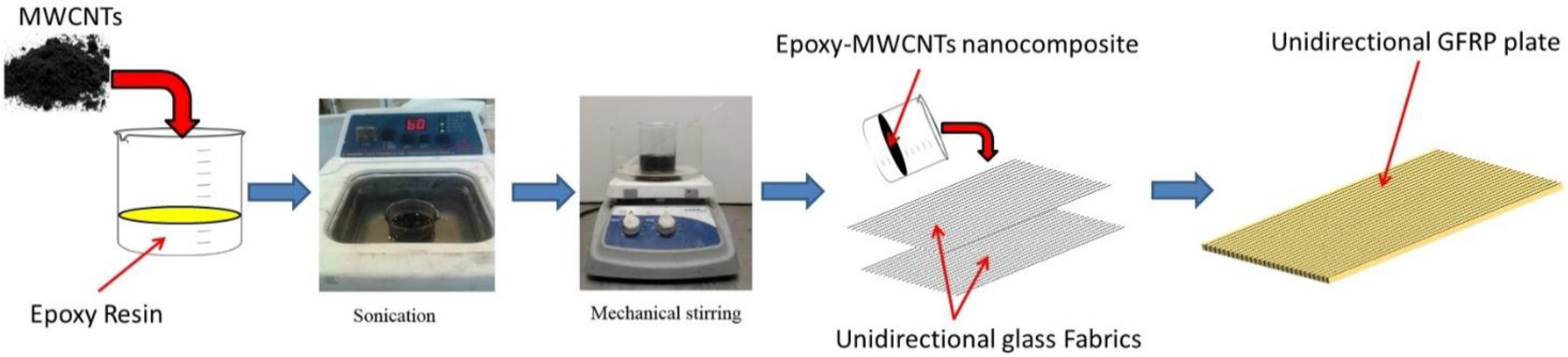
2.2. Preparing of Epoxy-MWCNTs Nanocomposites

Previous studies showed the effect of dispersion morphology on mechanical properties [29,30]. In order to obtain improvement in mechanical properties two conditions shall be achieved. First, a uniform dispersion of the CNTs through the matrix shall be achieved and second; a strong interfacial bond between the nanotubes and the surrounding matrix shall be achieved. Many techniques were developed to facilitate achieving these conditions, such as ultrasonications, high shear mixing, covalent and noncovalent functionalization.
Epoxy-MWCNTs nanocomposites with three different contents of MWCNTs (0 wt% (neat), 0.5 wt%, and 1.0 wt%) were prepared. The content of the MWCNTs in the nanocomposites was calculated as a weight percentage of total weight of epoxy. To disperse the MWCNTs in the epoxy, the MWCNTs were first manually stirred in the epoxy resin for 1 min. Afterward, the epoxy resin-MWCNTs mixture was sonicated in an ultrasonication bath for 1 h at 40 °C to extricate the MWCNTs. The mixture was then mechanically stirred using a magnetic stirrer for 2 h at 80 °C and 800 rpm to insure uniform dispersion of the MWCNTs in the epoxy resin. The mixture was allowed to cool down for 1 h at room temperature and then the epoxy hardener was added and mixed until a uniform mixture was obtained.

2.3. GFRP Fabrications and Specimens Preparation

The neat epoxy and the epoxy-MWCNTs nanocomposites were used to fabricate of the GFRP plates guided by ASTM D5687-95 [31]. The plates were fabricated using the vacuum assisted hand layup technique. Six layers of unidirectional glass fiber were laid in 0° fiber orientation. A thin layer of epoxy was spread before and after each glass fiber layer using a roller. Pressure of 2.3 × 10⁻² Torr was then applied to the fibers and the epoxy layers for 24 h. Figure 1 shows a schematic diagram for preparation of MWCNTs-epoxy nanocomposite and fabrication of GFRP plates. After fabrication, the GFRP plates were air cured for 14 days. The GFRP plates were then cut into 125 mm × 12.5 mm coupons. The thickness of the coupons was 1.03 ± 0.03 mm. Moreover, the fiber volume fraction for each type of the GFRP composites was determined according to ASTM D3171-06 [32]. The mean fiber volume fraction for the GFRP composites incorporating 0 wt% (neat), 0.5 wt%, and 1.0 wt% MWCNTs was found to be 55.2%, 51.5%, and 53.0%, respectively, confirming that the three GFRP composites with and without MWCNTs were of close fiber content.
Figure 1. Schematic diagram for preparation of Multi-Wall Carbon Nanotubes (MWCNTs) epoxy nanocomposites and the fabrication of glass fiber reinforced polymers (GFRP) plates.
Fibers 03 00013 g001

2.4. Test Methods

2.4.1. Static Tension Test

The GFRP coupons were tested under static and cyclic tension loads. Loads were applied using MTS® Bionex servo hydraulic system with mechanical grips. Five coupons of each type of GFRP composite were tested under static tension load guided by ASTM D3039-08 [33]. The load was applied in a displacement control protocol with 1 mm/min. loading rate. The applied load and displacement were recorded through the test with a 1 Hz. sampling rate. A contact extensometer with gauge length of 25.4 mm was used to measure the strain in the GFRP composite. The strain measured by the extensometer was then compared to the strain calculated using the displacement of the machine crosshead. The difference between the measured and the calculated strain was found to be less than 2%. Thus, the displacement obtained from the machine crosshead was considered for the strain calculations.

2.4.2. Cyclic Tension Test

An additional five coupons of each GFRP group were tested under cyclic tension test according to ASTM D3479-12 [34]. The main objective of the cyclic tension test is to compare the fatigue life for different GFRP composites subjected to one mean stress level. The specimens were subjected to ramp loading with a rate of 25 N/s until the stress reached 344 MPa, equivalent to 70% of the maximum tensile strength. Then, the specimen was subjected to cyclic load with mean stress of 197 MPa, equivalent to 40% of the maximum tensile strength, and amplitude of 148 MPa, equivalent to 30% of the maximum tensile strength, with a loading frequency of 1 Hz. This specific stress cycle (ranging between 10% and 70% of the tensile strength of GFRP) was chosen for fatigue testing to simulate the effect of significantly high stress cycles beyond typical service loads observed by GFRP in bridges. Most design codes (e.g., American Concrete Institute [11]), suggest limiting the mean fatigue stress of GFRP below 20% of its ultimate strength. By testing GFRP between 10% and 70% (with a mean stress of 40%) of its tensile strength, we demonstrate the significant improvement MWCNTs can provide to the fatigue life of GFRP under severe stress cycles. The displacement and the applied load were recorded using data acquisition system with 100 Hz. sampling rate. The GFRP coupons were subjected to tension cyclic load until failure.

2.4.3. Microstructure Characterization

First, the dispersion of the MWCNTs in epoxy was examined using Scanning Electron Microscope (SEM). The microscopy investigation was conducted on the epoxy-MWCNTs nanocomposites with 0.5 wt% and 1.0 wt% MWCNTs. Furthermore, microstructural characterization using Fourier Transform Infrared (FTIR) spectroscopy to understand the chemical effect of incorporating functionalized MWCNTs in the epoxy matrix was conducted. FTIR analysis was conducted on 25.4 mm × 25.4 mm GFRP specimen. One specimen was cut from each plate of the three GFRP composite groups. Nicolet Nexus 670 Micro-Fourier Transform Infrared Spectroscopy (Micro-FTIR) biconical reflectance was used for the analysis. The FTIR has a continuum microscope with a Globar source, XT-KBr beam splitter and a MCT-A detector over a 100 × 100 micron area with a 4-cm−1 resolution. A reflective gold slide was used for spectra background correction. The spectra were then converted to absorbance using the Kramers-Kronig equation as per FTIR analysis method [35].

3. Results and Discussion

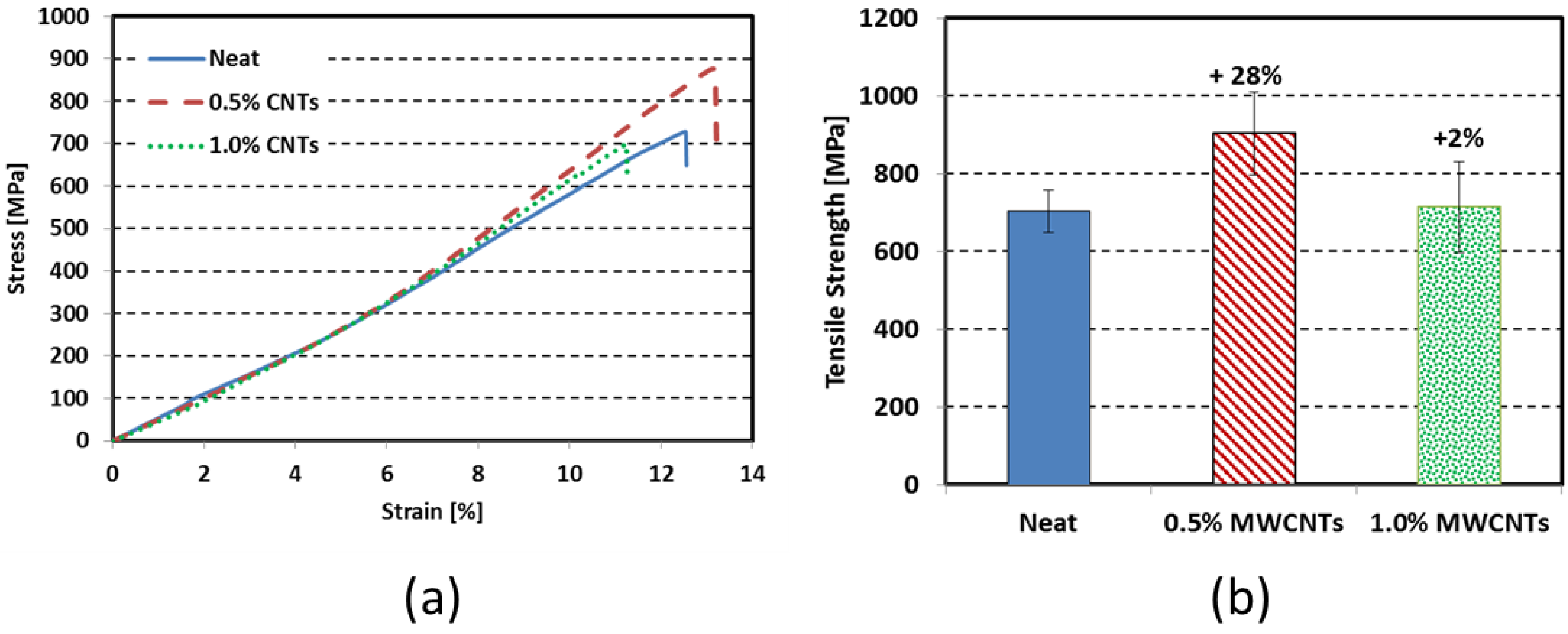
3.1. Tensile Strength

GFRP composite coupons were tested under static tension loads up to failure. The tensile strength for the individual specimen is presented in Table 1. Median stress-strain curves for the GFRP materials with different MWCNTs content are shown in Figure 2a. It can be observed from Figure 2a that incorporating MWCNTs had no effect on the tension modulus of elasticity of GFRP composites at low strain level. This can be attributed to the fact that the stiffness of glass fibers dominates the elastic response of GFRP for being much higher stiffness compared with the epoxy matrix. However, at high strain levels it was observed that GFRP composites incorporating MWCNTs are stiffer than the neat ones. The increase of stiffness associated with the increase in strain is attributed to the effect of fiber straightening during test. In a vacuum assisted hand layup fabrication technique, the fibers would not be fully stretched during the fabrication of the GFRP composites process. As the strain increases, the fibers stretch and the stiffness increases accordingly as reported by others [36,37,38]. However with the increase of strain level, the damage accumulates in the matrix and initiates debonding between the matrix and the fibers. This results in decreasing the stiffness and counteracts the effect of the fiber stretching. In case of CNTs-epoxy nanocomposites, the CNTs improve the bond between the matrix and the fibers and therefore limit the damage at the interface while the stiffness keeps increasing due to the fiber stretching. Thus, more stiffening was observed in the case of GFRP incorporating 0.5 wt% and 1.0 wt% MWCNTs-epoxy nanocomposites than that observed in neat GFRP composites. On the other hand, the mean tensile strength for the five coupons in each GFRP composite group was found to be 703 ± 55 MPa, 904 ± 107 MPa, and 714 ± 117 MPa for the GFRP composites incorporating 0 wt% (neat), 0.5 wt%, and 1.0 wt% MWCNTs respectively. The results show the tensile strength of the GFRP composites increased by 28% for 0.5 wt% MWCNTs-epoxy nanocomposite matrix. However, very limited increase of only 2% was observed for 1.0 wt% MWCNTs -epoxy nanocomposite matrix. A bar chart for comparison is presented in Figure 2b.
Table 1. Tensile strength (MPa) for individual Glass Fiber Reinforced Polymer (GFRP) coupons.
Specimen numberTensile strength (MPa)
Neat0.5 wt% MWCNTs1.0 wt% MWCNTs
1690891680
2783763595
37291058909
4657931699
5650876688
Mean703904714
Standard deviation55107117
Figure 2. (a) Example median stress-strain curves for the neat, 0.5%, and 1.0% MWCNTs under static tension load; (b) maximum tensile strength for the neat, 0.5%, and 1.0% MWCNTs. % presented represent the improvement of the tensile strength of GFRP composites compared to reference (neat).
Fibers 03 00013 g002
Statistical analysis using student t-test with 95% level of confidence shows that the increase in the tensile strength of the GFRP composites incorporating 0.5 wt% MWCNTs was statistically significant. On the other hand, the difference in the tensile strength between the neat GFRP and GFRP coupons incorporating 1.0 wt% MWCNTs was statistically insignificant. The failure modes of GFRP composites incorporating different MWCNTs content are shown in Figure 3. It is obvious that incorporating MWCNTs in epoxy matrix alters the failure mode of the GFRP composites. A typical broom-like failure of the GFRP composites was observed in the coupons fabricated using neat epoxy due to the weak interfacial bond between glass fibers and the epoxy matrix as reported by others [39,40,41]. However, the figure shows that incorporating 0.5 wt% and 1.0 wt% MWCNTs significantly limited the broom-like failure of the GFRP composites giving a sign of enhancing the cohesive strength of the epoxy nanocomposite matrix.
Figure 3. Failure modes of the GFRP composites including 0% MWCNTs (neat), 0.5% MWCNTs, and 1.0% MWCNTs.
Fibers 03 00013 g003
Moreover, the strain at failure for the GFRP composites incorporating 0 wt% (neat), 0.5 wt%, and 1.0 wt% MWCNTs was found to be 11.3%, 12.8%, and 10.7% respectively. The results show that the ductility was increased by 13% for the GFRP composites incorporating 0.5 wt% MWCNTs-epoxy nanocomposites and decreased by 5% for the GFRP composites incorporating 1.0 wt% MWCNTs-epoxy nanocomposites. Statistical analysis using student t-test with 95% level of confidence shows that difference in the ductility for the GFRP composites incorporating MWCNTs-epoxy nanocomposites were statistically significant.

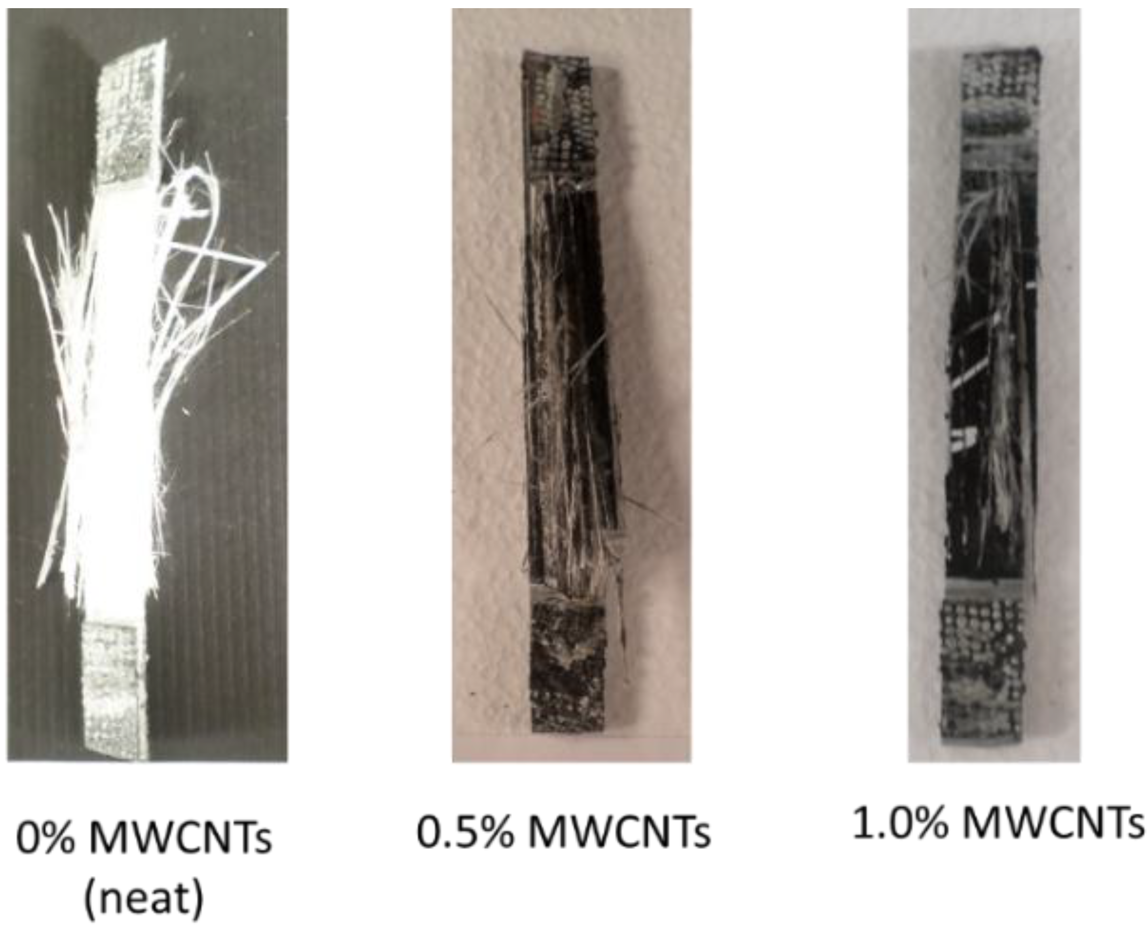
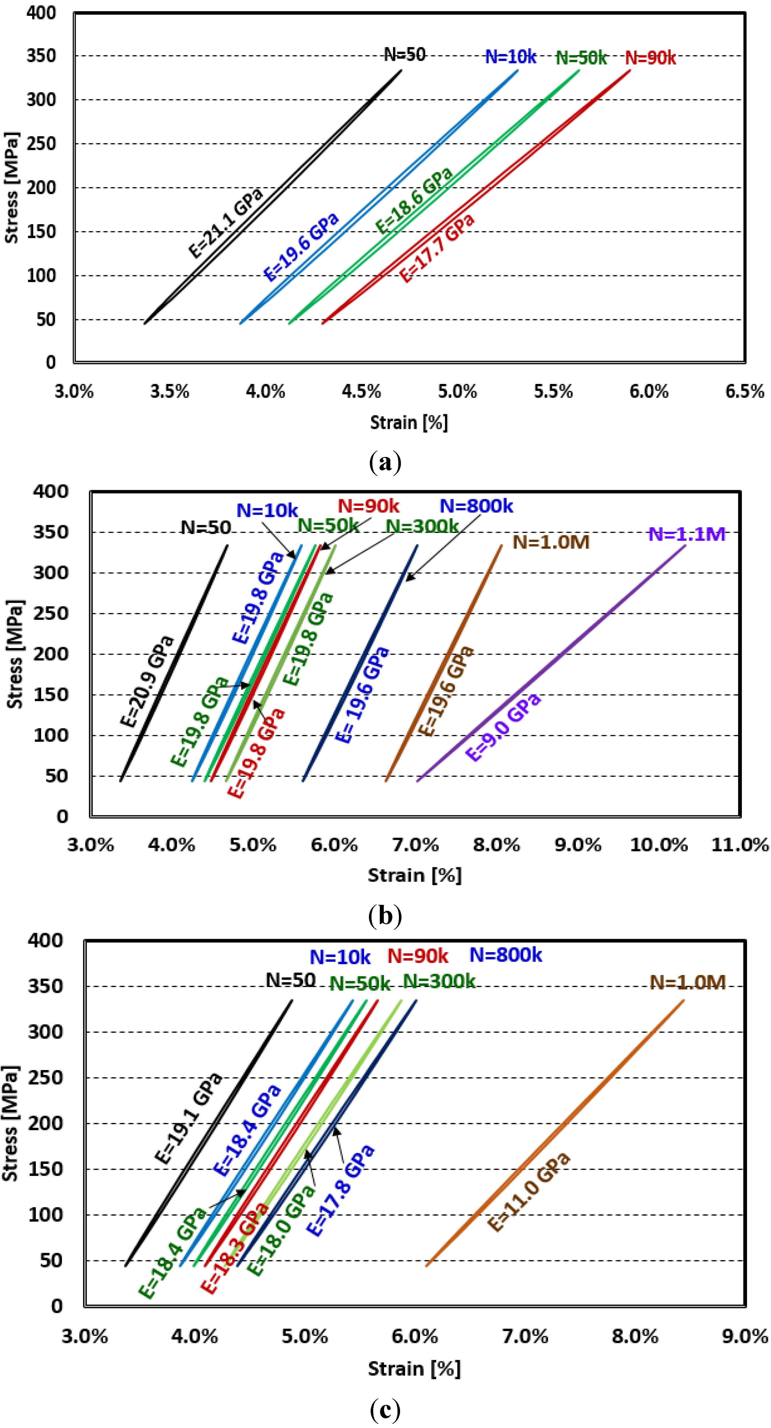
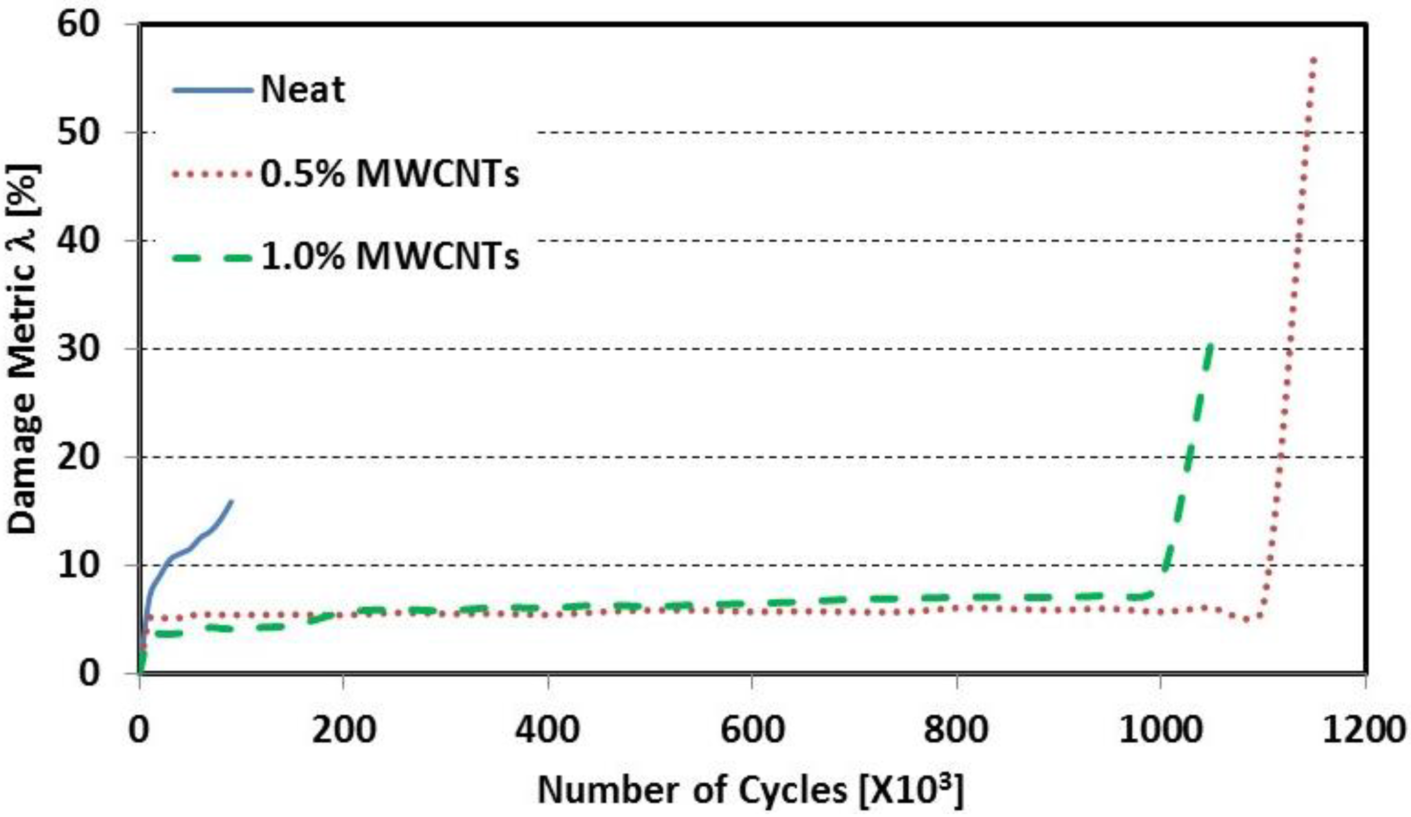
3.2. Damage Evolution
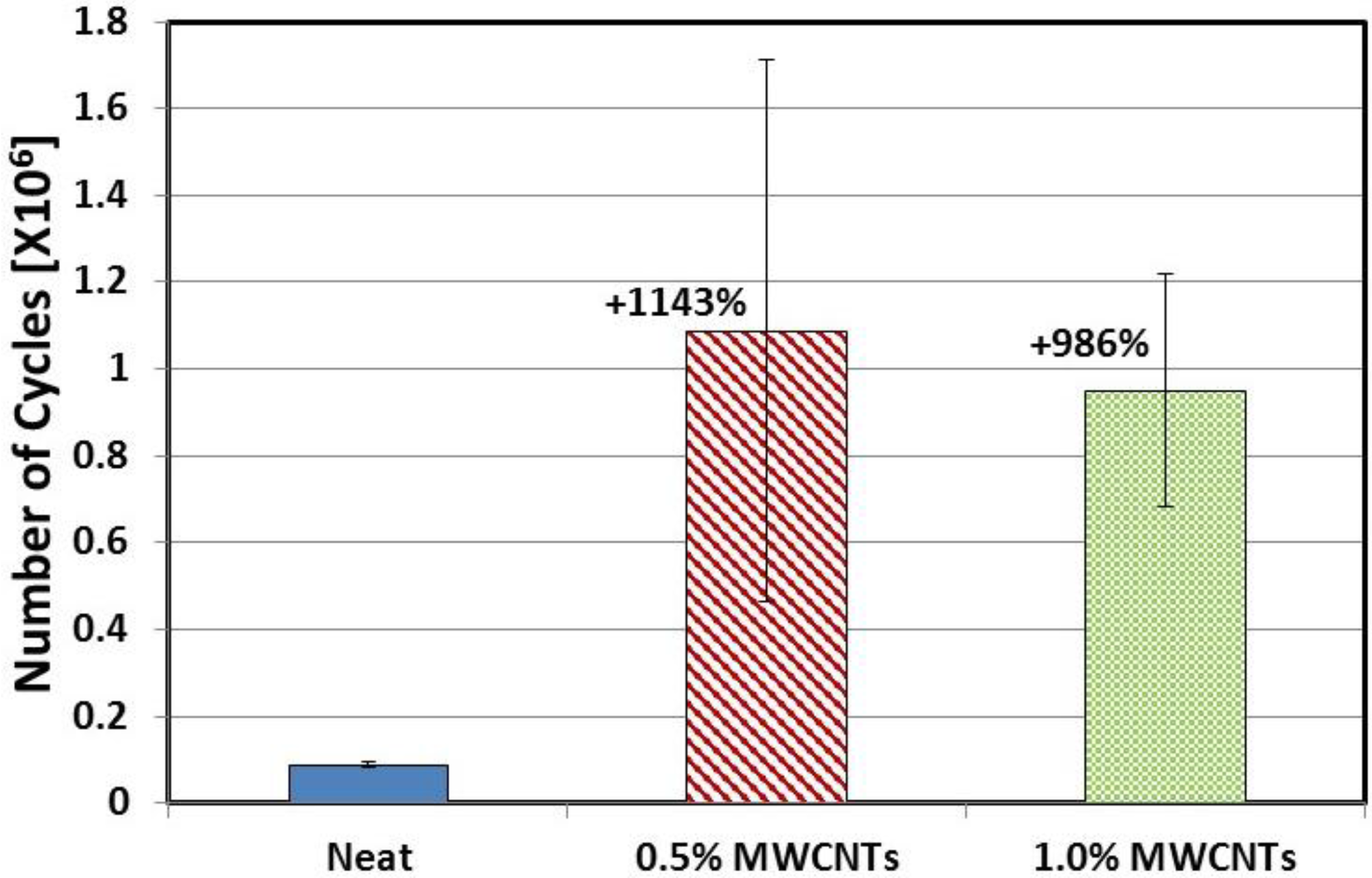
The stress-strain hysteresis during the loading cycles was used to calculate the secant modulus of elasticity at each cycle. Figure 4 shows the change in the stress-strain hysteresis for the GFRP composites as the number of cycles (N) increased. In general, it can be observed from Figure 4 that the use of MWCNTs significantly delayed the loss of stiffness and fatigue failure of the GFRP composites. To quantify damage propagation and loss of stiffness during cyclic loading, a damage metric (λ) was calculated as the reduction of the secant modulus of elasticity using Equation (1) after Lemaitre and Desmorat [42]. The initial modulus of elasticity (E0) was calculated at cycle number 50 for all the specimens to ensure that the stress-strain hysteresis became stable. The modulus of elasticity (Ei) was calculated at the ith cycle to generate the λ-N (damage versus number of cycles) relationship for each type of GFRP composite as shown in Figure 5.
λ ( i ) = E 0 E i E 0 %
where λ(i) is the damage metric at the ith cycle reported as percentage.
Figure 4. Change in stress-strain hysteresis for GFRP composites incorporating (a) 0% MWCNTs (neat); (b) 0.5% MWCNTs; (c) 1.0% MWCNTs. (N is number of cycles).
Fibers 03 00013 g004
Figure 5. Median λ-N curve for the GFRP specimens with and without MWCNTs.
Fibers 03 00013 g005
It is apparent from Figure 5, that incorporating 0.5 wt% and 1.0 wt% MWCNTs in epoxy was able to significantly increase the mean fatigue life of GFRP from 87.51 ± 5.6 k (neat) to 1.09 ± 0.62 M (0.5 wt% MWCNTs) and 0.95 ± 0.27 M (1.0 wt% MWCNTs) representing an increase of 1143% and 986%, respectively, as shown in Figure 6. The improvement of fatigue life of GFRP is exceptional, reaching one order of magnitude. Although the variability of the fatigue life of GFRP coupons was relatively high, the minimum fatigue life achieved by incorporating MWCNTs in the GFRP composites was 530 k cycles. Significant scatter in fatigue life of composites was reported by other researchers and is attributed to heterogeneous nature, higher sensitivity to batch variability, and complex failure modes of composite materials [43]. This represents a minimum fatigue life improvement of 500%. Table 2 shows the fatigue life of individual GFRP composite coupons. Statistical student t-test was conducted and showed the increase of the fatigue life for both the 0.5 wt% MWCNTs and 1.0 wt% MWCNTs to be statistically significant with a 95% level of confidence. However, the difference between the 0.5% and the 1.0% MWCNTs was statistically not significant.
Figure 6. Number of cycles in million until failure for the neat, 0.5% MWCNTs, and 1.0% MWCNTs. % presented represents the improvement of the number of cycles to failure of GFRP composites compared to reference (neat).
Fibers 03 00013 g006
Table 2. Fatigue life (Number of cycles until failure) for individual GFRP coupons.
Specimen numberFatigue life (number of cycles until failure)
Neat0.5 wt% MWCNTs1.0 wt% MWCNTs
185,138531,006637,398
292,1112,082,378702,837
379,543585,0781,125,000
487,4721,094,8551,246,330
593,3011,144,0951,042,000
Mean87,5131,087,482950,713
Standard deviation5,563623,526267,258
The above observations on both the static and cyclic tensile strength of GFRP incorporating MWCNTs can be explained by our hypothesis that COOH functionalized MWCNTs react chemically with the epoxy and produce a new MWCNTs-epoxy nanocomposite that has a higher bond (adhesion) strength with glass fibers than neat epoxy and a higher shear (cohesive) strength of the MWCNTs-epoxy nanocomposite compared with neat epoxy. This hypothesis is schematically presented in Figure 7 showing potential chemical reactions of the COOH functional group with epoxy and silane sizing of glass fibers creating high adhesion/bond strength and improving epoxy crosslinking that increases cohesion/shear strength of the epoxy matrix. The improvement of the tensile strength of GFRP by 28% of GFRP incorporating 0.5 wt% MWCNTs is attributed to the enhancement in the adhesion/bond strength between the fibers and the matrix. It is well established that tension failure of GFRP is initiated by adhesion failure of glass fibers and epoxy [44]. The inability of the 1.0 wt% MWCNTs to improve the GFRP tensile strength can be explained by the significant effect of increasing MWCNTs content on the viscosity of epoxy, which in turn resulted in an observable increase in epoxy viscosity. While this viscosity increase might do little to affect the chemical reaction between epoxy and MWCNTs within the nanocomposite, as it takes place during the sonication and mechanical stirring processes, it would significantly hinder the ability of epoxy to impregnate the glass fibers cloth during the fabrication process. It is possible that the use of 1.0 wt% MWCNTs improves the cohesion strength of the matrix but does not improve the adhesion strength of the matrix with glass fibers.
One-hundred-times (×100-magnified) microscopic imaging of the failure region in GFRP composites was conducted to examine the hypothesis presented in Figure 7. As apparent in Figure 8a, the fibers in the case of GFRP with neat epoxy was completely pulled-out of the epoxy matrix leading to complete broom like failure with many apparent individual glass fibers. Figure 8b shows ×100-magnified image of GFRP composites incorporating 0.5 wt% MWCNTs in which small pieces of the epoxy matrix remained intact with the glass fibers. The strong bond enabled the epoxy nanocomposite to hold the fibers together and thus reduce the broom effect. On the other hand, incorporating 1.0 wt% MWCNTs (Figure 8c) showed a large chunk of the epoxy nanocomposite matrix attached to the fibers at the failure area while some of the fibers were also pulled-out of the epoxy nanocomposite matrix individually. The case with 1.0% MWCNTs created mixed failure pattern with some broom like effect that is less than that of the neat epoxy. As a result, insignificant improvement of tensile strength was observed with the addition of 1.0 wt% MWCNTs. The above hypothesis would also explain the change in the failure mode of GFRP incorporating both 0.5 wt% and 1.0 wt% MWCNTs as both MWCNTs contents would result in improving the cohesion strength of the GFRP matrix. The improved cohesion strength of epoxy limited the broom-like failure of both 0.5 wt% and 1.0 wt% MWCNTs as shown in Figure 3 and Figure 8, although they exhibited different tensile strengths (Figure 2b).
Figure 7. Hypothesized schematic for chemical reaction between COOH functionalized MWCNTs and epoxy that improves bond between glass fibers and epoxy incorporating COOH functionalized MWCNTS. (a) Typical inter fiber fracture; (b) adhesion/bond cracks and cohesion/shear cracks are limited with the addition of Carbon Nanotubes (CNTs); and (c) potential chemical reactions that improve adhesion/bond strength and cohesive/shear strength of the fiber/matrix interface and epoxy matrix respectively.
Fibers 03 00013 g007
Figure 8. One-hundred-times-magnified microscopic imaging on the failure region in GFRP composites incorporating (a) 0 wt% (neat); (b) 0.5 wt%; and (c) 1.0 wt% MWCNTs.
Fibers 03 00013 g008
The above hypothesis can also explain the significant improvement of the fatigue life achieved by incorporating MWCNTs in epoxy. Fatigue cracks in GFRP are typically initiated by debonding at the fiber/epoxy interface (adhesion failure) and propagate as interlaminar and/or intralaminar cracks (cohesion failure). The fact that both 0.5 wt% and 1.0 wt% MWCNTs were able to significantly improve the fatigue life while 0.5 wt% MWCNTs only were able to improve the static tensile strength can be explained by the fact that fatigue life is strongly dependent on matrix crack propagation resistance/cohesion strength which would have been improved for both MWCNTs contents. It is, therefore, suggested that COOH functionalized MWCNTs improve the cohesive/shear strength of the epoxy matrix and enhance the capability of the epoxy matrix to resist fatigue crack propagation.

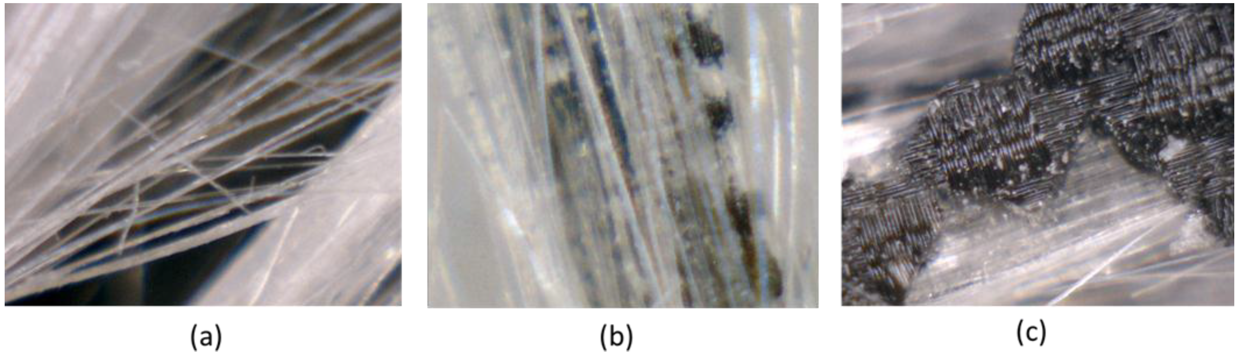
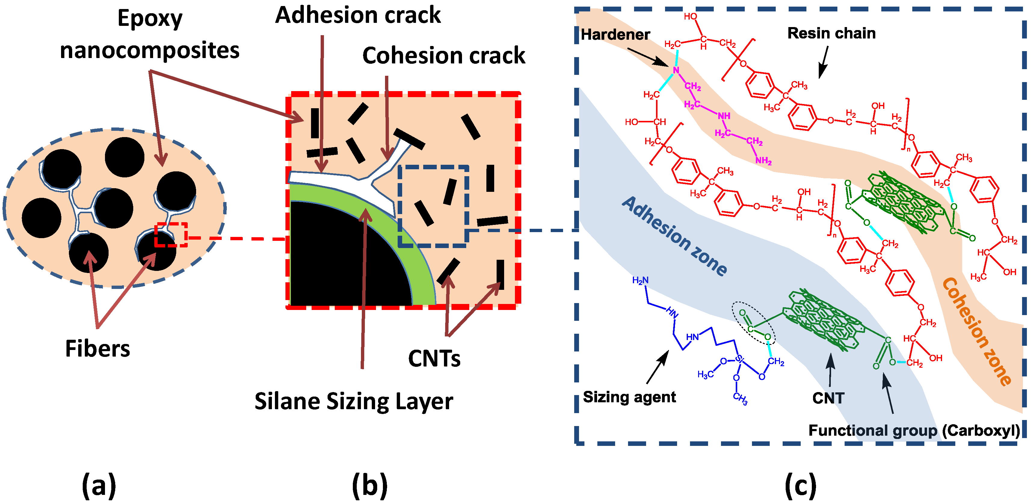
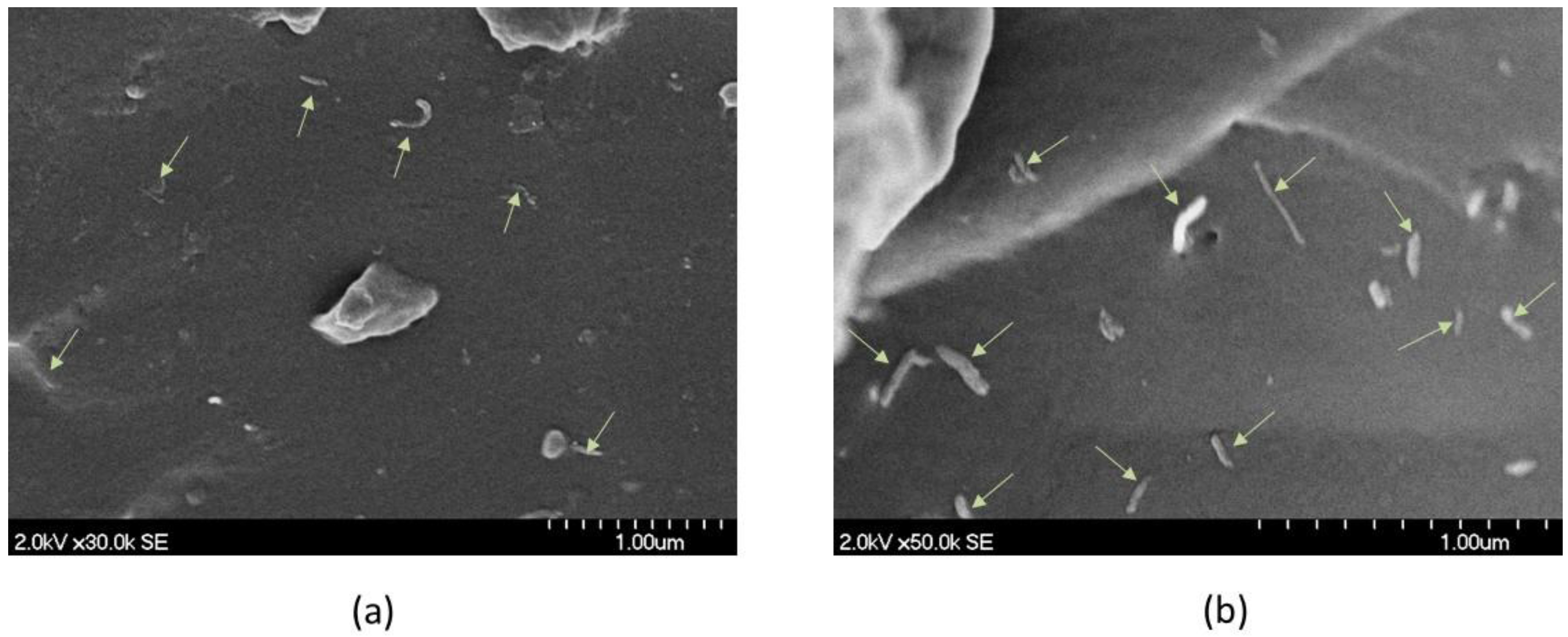
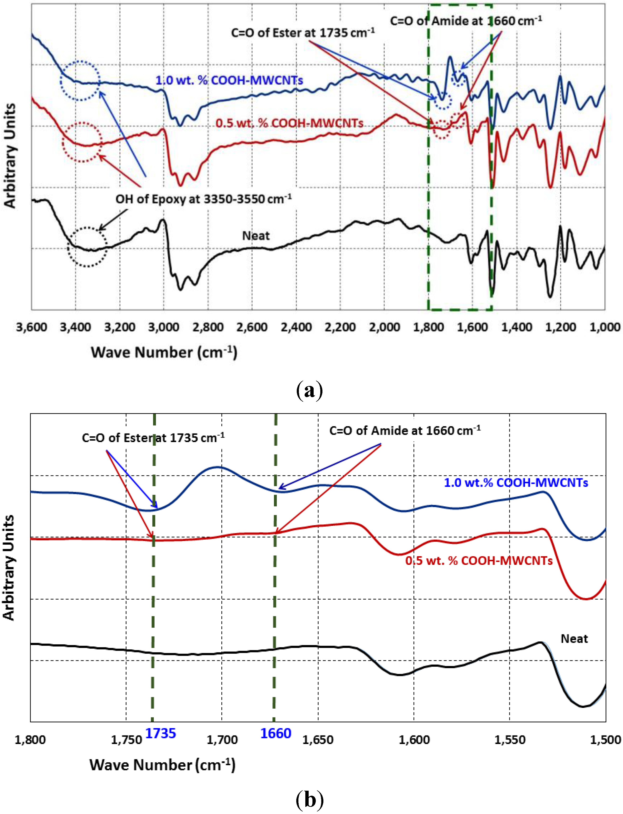
3.3. Microstructure Characterization

Figure 9 shows the dispersion of the 0.5 wt% and the 1.0 wt% MWCNTs in the epoxy nanocomposites. The marked arrows in Figure 9 indicate MWCNTs in the epoxy matrix. It is apparent from Figure 9 that the MWCNTs are well dispersed as single individual nanotubes and not bundled together. This good dispersion enables the suggested chemical reaction to take place and also allows MWCNTs to work as fibers bridging the nano and microcracks and therefore delaying fatigue crack propagation in the epoxy matrix. To prove the above hypothesis, FTIR spectra for the three GFRP composites were examined as shown in Figure 10a.
Two specific peaks can be observed in the FTIR spectrum being the C=O stretches for the carbonyl group at 1735 cm−1 and for the amide group at 1660 cm−1. The peaks are weakly apparent in epoxy with 0.5 wt% MWCNTs but are strongly apparent in epoxy with 1.0 wt% MWCNTs. The peak at 1735 cm−1 is a classical peak representing Ester formation (i.e., esterification), which would take place as a reaction between the COOH group and the epoxy resin [45]. Furthermore, the peak at 1660 cm−1 is reported to represent the formation of amide as a result of reaction of the COOH group and the amine-based hardener [46]. A close look at the FTIR spectrum where both peaks appear is shown in Figure 10b. It becomes obvious from Figure 10b that these peaks are all missing in the neat epoxy. The strong appearance of the two peaks with epoxy incorporating 1.0 wt% MWCNTs compared with epoxy incorporating 0.5 wt% MWCNTS is attributed to the higher quantity of the COOH in the former compared with the latter. We also note in Figure 10a that other classical peaks of epoxy at 3350 cm−1 appearing in all three materials with and without MWCNTs. The above FTIR observations confirm our hypothesis that the addition of COOH functionalized MWCNTs to amine-based epoxy resulted in chemical reaction and the formation of a new epoxy-MWCNTs nanocomposite with improved mechanical properties, including adhesion with glass fibers and cohesion strength of GFRP matrix. Such chemical reaction between the COOH functionalized MWCNTs and epoxy were reported to improve the dispersion of the MWCNTs in the epoxy and enhance the mechanical properties of the MWCNTs-epoxy nanocomposites significantly [27,47].
Figure 9. SEM images showing dispersion of (a) 0.5 wt% MWCNTs; (b) 1.0 wt% MWCNTs in epoxy.
Fibers 03 00013 g009
Figure 10. FTIR spectrum for the epoxy incorporating 0 wt% (neat), 0.5 wt%, and 1.0 wt% MWCNTs showing main peaks (a) complete spectrum (b) zoomed area 1500–1800 cm−1.
Fibers 03 00013 g010
Our investigation showed that MWCNTs-epoxy nanocomposite could significantly improve the fatigue life of GFRP composites such that fatigue design limitations can be eliminated. While the above investigation has limitations represented by (1) the method of GFRP fabrication which would typically introduce relatively high variability; (2) the limited number of layers in fabricating GFRP; and (3) the relatively high mean stress of cyclic loading applied, the above study still sheds light on the potential of using MWCNTs in improving the fatigue performance of GFRP. The improvement in the fatigue life was remarkable reaching one order of magnitude allowing GFRP to pass the one million-cycle mark compared with GFRP incorporating neat epoxy that did not reach 100,000 cycles. The ability of MWCNTs to improve the tensile strength and the fatigue life of GFRP in a tension-tension fatigue test proves the well dispersion of MWCNTs along the GFRP length and across the thickness. This is attributed to the fact that fatigue failure under tension is dominated by a single critical crack [48]. The ability to improve the tensile strength and fatigue life of GFRP means MWCNTs limited crack propagation of that critical crack within the whole coupon. This further proves the well dispersion of MWCNTs within the whole coupon. Furthermore, microstructural investigations proved the good dispersion of MWCNTs in the epoxy matrix and provided evidence of chemical reaction of the functionalized MWCNTs with epoxy. Moreover, with the percolation threshold for MWCNTs of 0.5 wt%, the dispersion and damage evolution can be assessed using electrical measurements as presented by the authors elsewhere [49]. In general, it is evident that GFRP without the current fatigue limitations can be produced using MWCNTs. The fact that MWCNTs are added at a very low quantity (0.5 wt% of the weight of epoxy) makes insignificant addition to GFRP manufacturing cost.

4. Conclusions

Incorporating 0.5 wt% MWCNTs in epoxy improved the tensile strength and fatigue life of the GFRP coupons by 28% and 1143%, respectively. Tensile strength and fatigue life of GFRP composites incorporating 1.0 wt% MWCNTs were improved by 2% and 986%, respectively. Statistical analysis confirmed that the improvements in fatigue life using 0.5 wt% and 1.0 wt% MWCNTs were significant. The improvement of tensile strength and fatigue life of GFRP composites incorporating MWNCTs was associated with absence of the classical broom-like failure mode.
We hypothesize that the significant improvement in tensile strength and fatigue life of GFRP incorporating COOH functionalized MWCNTs is attributed to the chemical reaction between the COOH group and epoxy forming a new epoxy-MWCNTs nanocomposite with improved adhesion strength with glass fibers and cohesion strength within the epoxy matrix. However, increasing MWCNTs content increases epoxy viscosity, which would hinder epoxy impregnation during GFRP composite fabrication and thus affects epoxy bond with glass fibers. The non-significant effect of 1.0 wt% on tensile strength of GFRP compared with 0.5 wt% of MWCNTs is attributed to the fact that the tensile strength of GFRP is significantly governed by adhesion of epoxy and glass fibers. The ability of both 0.5 wt% and 1.0 wt% MWCNTs contents to improve fatigue life of GFRP is attributed to the fact that fatigue of GFRP is more governed by matrix cohesion that controls fatigue crack propagation and is significantly improved with the addition of MWCNTs. As GFRP incorporating MWCNTs remarkably passed the one million-cycle mark at a relatively high mean stress, it is concluded that a new GFRP without fatigue limitations for infrastructure applications can be produced using MWCNTs. More work is needed to investigate the effect of MWCNTs on the fatigue strength of GFRP by examining fatigue life at different stress levels. Moreover, additional CNTs contents between 0.2 wt% and 0.8 wt% need to be investigated to achieve the optimum CNTs content.

Acknowledgments

This work was funded by US National Science Foundation (NSF) Award No. OISE-1103601 to University of New Mexico. The authors greatly acknowledge this support.

Author Contributions

Sherif Daghash designed the tension test set-up. Moneeb Genedy and Sherif Daghash performed the static and cyclic tension tests; Moneeb Genedy and Eslam Soliman conducted the microstructure characterization and data analysis and Mahmoud Reda Taha directed the research and contributed to the data analysis and interpretation of the experimental studies.

Conflicts of Interest

The authors declare no conflict of interest.

References

  1. Einde, L.V.D.; Zhao, L.; Seible, F. Use of FRP composites in civil structural applications. Constr. Build. Mater. 2013, 17, 389–403. [Google Scholar] [CrossRef]
  2. Hollaway, L.C. The evolution of and the way forward for advanced polymer composites in the civil infrastructure. Constr. Build. Mater. 2003, 17, 365–378. [Google Scholar] [CrossRef]
  3. Wight, R.G.; Erik, M.A.; Shgu, C.T.; Tanovic, R.; Heffernan, P.J. Development of FRP short-span deployable bridge—Experimental results. J. Bridge Eng. 2006, 11, 489–498. [Google Scholar] [CrossRef]
  4. Park, K.; Yu, Y.; Shin, H. Span length variance effect on the fatigue life of FRP bridge deck. Adv. Mater. Sci. Eng. 2013, 2013, 1–10. [Google Scholar]
  5. Wu, Z.; Wang, X.; Iwashita, K.; Sasaki, T.; Hamaguchi, Y. Tensile fatigue behaviour of FRP and hybrid FRP sheets. Compos. Part B 2010, 41, 396–402. [Google Scholar] [CrossRef]
  6. Kumar, P.K.; Chandrashekhara, K.; Nanni, A. Structural performance of a FRP bridge deck. Constr. Build. Mater. 2004, 18, 35–49. [Google Scholar] [CrossRef]
  7. Zheng, Y.; Guoyou, Y.; Yungfeng, P. Investigation of ultimate strengths of concrete bridge deck slabs reinforced with GFRP bars. Constr. Build. Mater. 2012, 28, 482–492. [Google Scholar] [CrossRef]
  8. Brown, D.L.; Berman, J.W. Fatigue and strength evaluation of two glass fiber reinforced polymer bridge decks. J. Bridge Eng. Am. Soc. Civ. Eng. 2010, 15, 290–301. [Google Scholar]
  9. Noël, M.; Soudki, K. Fatigue behavior of GFRP reinforcing bars in air and in concrete. J. Compos. Constr. 2014, 18, 1–8. [Google Scholar] [CrossRef]
  10. Kim, J.K.; Mai, Y.W. Engineered Interfaces in Fiber Reinforced Composites, 1st ed.; Elsevier: Oxford, UK, 1998. [Google Scholar]
  11. Guide for the Design and Construction of Externally Bonded FRP Systems for Strengthening Concrete Structures; ACI Committee: Farmington Hills, MI, USA, 2008; ACI Committee 440.2R-08.
  12. Canadian Standard Association (CSA) S6. Canadian Highway Bridge Design Code; CSA: Mississauga, ON, Canada, 2010. [Google Scholar]
  13. Agubra, V.; Owuor, P.; Hosur, M. Influence of nanoclay dispersion methods on the mechanical behavior of E-Glass/Epoxy nanocomposites. Nanomaterials 2013, 2, 550–563. [Google Scholar] [CrossRef]
  14. Aboubakr, S.H.; Kandil, U.F.; Reda Taha, M.M. Creep of epoxy-clay nanocomposite adhesive at the FRP interface: A multi-scale investigation. Int. J. Adhes. Adhes. 2014, 54, 1–12. [Google Scholar] [CrossRef]
  15. Meng, Q.; Wang, C.H.; Saber, N.; Kuan, H.C.; Dai, J.; Friedrich, K.; Ma, J. Nanosilica-toughened polymer adhesives. Mater. Des. 2014, 61, 75–86. [Google Scholar] [CrossRef]
  16. Kim, H.; Miura, Y.; Macosko, C.W. Graphene/polyurethane nanocomposites for improved gas barrier and electrical conductivity. Chem. Mater. 2010, 22, 3441–3450. [Google Scholar] [CrossRef]
  17. Wang, S.; Qiu, J. Enhancing thermal conductivity of glass fiber/polymer composites through carbon nanotubes incorporation. Compos. Part B Eng. 2010, 41, 533–536. [Google Scholar] [CrossRef]
  18. Manjunatha, C.M.; Bojja, R.; Jangannathan, N.; Kinloch, A.J.; Taylor, A.C. Enhanced fatigue behavior of a glass fiber reinforced hybrid particles modified epoxy nanocomposite under WISPERX spectrum load sequence. Int. J. Fatigue 2013, 54, 25–31. [Google Scholar] [CrossRef]
  19. Wang, S.; Qiu, J. Modifying epoxy resin via M-chloroperbenzoic acid epoxidized carbon nanotubes. J. Appl. Polym. Sci. 2009, 112, 3322–3326. [Google Scholar] [CrossRef]
  20. Wang, S.; Liang, R.; Wang, B.; Zhang, C. Addition of diethyltoluenediamines onto carbon nanotubes for efficient load-transfer in the nanocomposites. Polym. Compos. 2009, 30, 1050–1057. [Google Scholar] [CrossRef]
  21. Qiu, J.; Zhang, C.; Wang, B.; Liang, R. Carbon nanotube integrated multifunctional multiscale composites. Nanotechnology 2008, 18, 1–11. [Google Scholar]
  22. Soliman, E.; Al-Haik, M.; Reda Taha, M.M. On and off-axis tension behavior of fiber reinforced polymer (FRP) composites incorporating multi-walled carbon nanotubes. J. Compos. Mater. 2012, 46, 1661–1675. [Google Scholar] [CrossRef]
  23. Pandey, G.; Woltersd, M.; Thostenson, E.T. Localized functionally modified glass fibers with carbon nanotube networks for crack sensing in composites using time domain reflectometry. Carbon 2012, 50, 3816–3825. [Google Scholar] [CrossRef]
  24. Naghashpour, A.; Hoa, S.V. In-situ monitoring of through-thickness strain in glass fiber/epoxy composite laminates using carbon nanotube sensors. Compos. Sci. Technol. 2013, 78, 41–47. [Google Scholar] [CrossRef]
  25. Wang, S.; Liang, Z.; Liu, T.; Wang, B.; Zhang, C. Effective amino-functionalization of carbon nanotubes for reinforcing epoxy polymer composites. Nanotechnology 2006, 17, 1551–1557. [Google Scholar] [CrossRef]
  26. Wang, S.; Liang, R.; Wang, B.; Zhang, C. Load-transfer in functionalized carbon nanotubes/polymer composites. Chem. Phys. Lett. 2008, 457, 371–375. [Google Scholar] [CrossRef]
  27. Zhu, J.; Kim, J.; Peng, H.; Margrave, J.L.; Khabashesku, V.N.; Barrera, E.V. Improving the dispersion and integration of single-walled carbon nanotubes in epoxy composites through functionalization. Nano Lett. 2003, 3, 1107–1113. [Google Scholar] [CrossRef]
  28. Osorio, A.G.; Silveira, I.C.L.; Bueno, V.L.; Bergmann, C.P. H2SO4/HNO3/HCl—Functionalization and its effect on dispersion of carbon nanotubes in aqueous media. Appl. Surf. Sci. 2008, 255, 2485–2489. [Google Scholar] [CrossRef]
  29. Ma, P.C.; Siddiqui, N.A.; Marom, G.; Kim, J.K. Dispersion and functionalization of carbon nanotubes for polymer-based nanocomposites: A review. Compos. Part A Appl. Sci. Manuf. 2010, 41, 1345–1367. [Google Scholar] [CrossRef]
  30. Advani, S.G.; Fan, Z. Dispersion, bonding and orientation of carbon nanotubes in polymer matrices. In Processing and Properties of Nanocomposites; World Scientific Publishing Co., Pte. Ltd.: Hackensack, NJ, USA, 2007. [Google Scholar]
  31. Standard Guide for Preparation of Flat Composite Panels with Processing Guidelines for Specimen Preparation; ASTM International: West Conshohocken, PA, USA, 2007; ASTM D5687/D5687M-07.
  32. Standard Test Methods for Constituent Content of Composite Materials; ASTM International: West Conshohocken, PA, USA, 2006; ASTM D3171-06.
  33. Test Method for Tensile Properties of Polymer Matrix Composite Materials; ASTM International: West Conshohocken, PA, USA, 2008; ASTM D3039M-08.
  34. Standard Test Method for Tension-Tension Fatigue of Polymer Matrix Composite Materials; ASTM International: West Conshohocken, PA, USA, 2012; ASTM D3479/D3479M-12.
  35. Griffiths, P.; de Hasseth, J.A. Fourier Transform Infrared Spectrometry, 2nd ed.; Wiley-Blackwell: Hoboken, NJ, USA, 2007. [Google Scholar]
  36. Kuo, C.M.; Takahashi, K.; Chou, T.W. Effect of fiber waviness on the nonlinear elastic behavior of flexible composites. J. Compos. Mater. 1988, 22, 1004–1025. [Google Scholar] [CrossRef]
  37. Peel, L.D.; Jensen, D.W. The response of fiber-reinforced elastomers under simple tension. J. Compos. Mater 2001, 35, 96–137. [Google Scholar] [CrossRef]
  38. Chou, T.W. Microstructural Design of Fiber Composites; Cambridge University Press: Cambridge, UK, 2005. [Google Scholar]
  39. Greenhalgh, E.S. Failure Analysis and Fractography of Polymer Composites; Woodhead Publishing: Cambridge, UK, 2009. [Google Scholar]
  40. Kumar, M.S.; Raghavendra, K.; Venkataswamy, M.A.; Ramachandra, H.V. Fractographic analysis of tensile failures of aerospace grade composites. Mater. Res. 2012, 15, 990–997. [Google Scholar] [CrossRef]
  41. Bieniaś, J.; Surowska, B. The mechanical properties and failure analysis of selected fibre metal laminates. Compos. Theory Pract. 2012, 13, 220–224. [Google Scholar]
  42. Lemaitre, J.; Desmorat, R. Engineering Damage Mechanics: Ductile, Creep, Fatigue and Brittle Failures; Springer: Heidelberg, Germany, 2005. [Google Scholar]
  43. Tomblin, J.; Seneviratne, W. Determining the Fatigue Life of Component Aircraft Structures Using Life and Load-Enhancement Factors; Federal Aviation Administration: Washington, DC, USA, 2011. [Google Scholar]
  44. Strong, A.B. Fundamentals of Composites Manufacturing: Materials, Methods and Applications; Society of Manufacturing Engineers: Dearborn, MI, USA, 2008. [Google Scholar]
  45. Kim, W.-J.; Kang, S.-O.; Ah, C.S.; Lee, Y.-W.; Ha, D.H.; Choi, I.S.; Yun, W.S. Functionalization of shortened SWCNTs using esterification. Bull. Korean Chem. Soc. 2004, 25, 1301–1302. [Google Scholar] [CrossRef]
  46. Zhang, T.; Xu, M.; He, L.; Xi, K.; Gu, M.; Jiang, Z. Synthesis, characterization and cytotoxicity of phosphoryl choline-grafted water-soluble carbon nanotubes. Carbon 2008, 45, 1782–1791. [Google Scholar] [CrossRef]
  47. Gojny, F.H.; Wichmann, M.; Fiedler, B.; Schulte, K. Influence of different carbon nanotubes on the mechanical properties of epoxy matrix composites—A comparative study. Compos. Sci. Technol. 2005, 65, 2300–2313. [Google Scholar] [CrossRef]
  48. Suresh, S. Fatigue of Materials, 2nd ed.; Cambridge University Press: Cambridge, UK, 1998. [Google Scholar]
  49. Reda Taha, M.M.; Taha, E.O.; Genedy, M. Monitoring fatigue damage propagation in GFRP using carbon nanotubes. In Proceedings of the American Society for Composites 29th Technical Conference, 16th US-Japan Conference on Composite Materials, San Diego, CA, USA, 8–10 September 2014; DEStech Publications, Inc.: Lancaster, PA, USA, 2014. [Google Scholar]

