Article

Embedding 1D Euler Beam in 2D Classical Continua

by
Armine Ulukhanyan
1,*,
Luca Placidi
2,
Anil Misra
3,
Roberto Fedele
4,
Raimondo Luciano
5 and
Francesco Fabbrocino
2,*
1
Department of Information Engineering, Computer Science and Mathematics, Università degli Studi dell’Aquila, 67100 L’Aquila, Italy
2
Department of Engineering, Telematic University Pegaso, 80132 Naples, Italy
3
Department of Civil and Environmental Engineering, Florida International University, Miami, FL 33174, USA
4
Department of Civil and Environmental Engineering, Politecnico di Milano, 20133 Milano, Italy
5
Department of Engineering, Parthenope University of Naples, 80132 Naples, Italy
*
Authors to whom correspondence should be addressed.
Fibers 2025, 13(7), 88; https://doi.org/10.3390/fib13070088
Submission received: 31 December 2024 / Revised: 17 May 2025 / Accepted: 25 June 2025 / Published: 1 July 2025

Abstract

In this contribution, the classical Cauchy first-gradient elastic theory is used to solve the equilibrium problem of a bidimensional (2D) reinforced elastic structure under small displacements and strains. Such a 2D first-gradient continuum is embedded with a reinforcement, which is modeled as a zero-thickness interface endowed with the elastic properties of an extensional Euler–Bernoulli 1D beam. Modeling the reinforcement as an interface eliminates the need for a full geometric representation of the reinforcing bar with finite thickness in the 2D model, and the associated mesh discretization for numerical analysis. Thus, the effects of the 1D beam-like reinforcements are described through proper and generalized boundary conditions prescribed to contiguous continuum regions, deduced from a standard variational approach. The novelty of this work lies in the formulation of an interface model coupling 1D and 2D continua, based on weak formulation and variational derivation, capable of accurately capturing stress distributions without requiring full geometric resolution of the reinforcement. The proposed framework is therefore illustrated by computing, with finite element simulations, the response of the reinforced structural element under uniform bending. Numerical results reveal the presence of jumps for some stress components in the vicinity of the reinforcement tips and demonstrate convergence under mesh refinement. Although the reinforcement beams possess only axial stiffness, they significantly influence the equilibrium configuration by causing a redistribution of stress and enhancing stress transfer throughout the structure. These findings offer a new perspective on the effective modeling of fiber-reinforced structures, which are of significant interest in engineering applications such as micropiles in foundations, fiber-reinforced concrete, and advanced composite materials. In these systems, stress localization and stability play a critical role.

1. Introduction

The design and analysis of reinforced structural elements is a vital area of research in engineering, particularly when evaluating the performance of materials subjected to varying stress distributions. Reinforced elastic beams with various types of reinforcements have been extensively studied for their ability to enhance structural integrity and performance. Such beams find applications where mitigating fracture propagation or tensile failure is critical, especially in materials weak under tension. Integrating one-dimensional (1D) reinforcements into two-dimensional (2D) elastic continua is a powerful approach for improving mechanical performance across a broad spectrum of engineering applications. By embedding reinforcements with specific properties—such as negligible bending stiffness—into softer, more flexible matrices, these systems exploit the contrasting mechanical behaviors of the matrix and reinforcements to optimize structural integrity under nonuniform stress distributions.
The problem of coupling 1D and 2D domains has been addressed in numerous studies, each contributing innovative techniques to integrate elements of different dimensions and improve finite element analysis. The following studies have been fundamental in this approach: Hansbo et al. [1] proposed a hybridized Nitsche finite element approach for modeling elastic interfaces, allowing Euler–Bernoulli beams with axial stiffness to be weakly coupled to an elastic matrix. This method ensures compatibility without requiring conforming meshes. To extend such methodologies, Steinbrecher et al. [2] introduced a mortar-type approach for embedding curved 1D fibers in 3D solids. Their formulation enables flexible meshing using non-matching meshes while enforcing kinematic coupling constraints, which are critical for modeling fiber-reinforced materials. A more recent work by Steinbrecher et al. [3] advanced this idea with a full beam-to-solid volume coupling scheme, accounting for both translational and rotational degrees of freedom to ensure consistent 1D–3D coupling. This approach effectively avoids locking effects and supports modeling complex composites with curved, slender reinforcements. Further extending these principles, Yamamoto et al. [4] developed a Nitsche-based method for coupling shell and solid elements. By enforcing both displacement and stress vector continuity, their method addresses deformation irregularities at interfaces and introduces novel shell element formulations compatible with solid domains. Shim et al. [5] proposed a method for coupling beams, shells, and solids in elastic problems through multipoint constraint equations derived by equating work across dimensional interfaces. Their approach ensures compatibility while avoiding spurious stress artifacts, making it suitable for problems with significant stress gradients at dimensional transitions.
The coupling of a 1D beam element with a 2D continuum element is also a widely used technique, as seen in [6,7,8,9,10,11,12,13,14,15], particularly for complex systems where different domains exhibit distinct deformation behaviors. Each of these works uniquely advances the modeling of reinforced structures and composite materials, collectively enhancing the understanding of reduced-dimensional reinforcements embedded within higher-dimensional elastic systems. Together, they provide robust numerical techniques for structural analysis and engineering applications. Several complementary areas of research provide crucial insights into reinforced structural elements. Investigations into reinforcement mechanisms [16] have highlighted their significance in strengthening elastic matrices. Elasticity studies [17,18,19] further explore the deformation and stress distribution in reinforced systems, while works on elasticity and generalized continua [20,21,22] offer theoretical extensions to address microstructural effects. Research into metamaterials [23,24,25,26] demonstrates their ability to create tailored mechanical properties through reinforcement configurations. Variational methods [27,28] underpin many modeling techniques, enabling efficient energy-based formulations for complex systems. Homogenization approaches [29,30] allow multiscale analysis by linking microscale reinforcement behavior to macroscopic properties. Identification techniques [31] and computational methods [32,33] provide robust tools for characterizing and simulating reinforcement effects, ensuring accurate predictions of structural behavior under various conditions.
Despite this extensive body of literature, most existing approaches either require detailed meshing of the reinforcements or rely on strongly enforced continuity, which can lead to numerical locking and inefficiencies—particularly for reinforcements with negligible bending stiffness.
In this work, we propose an interface-based formulation that models 1D reinforcements as zero-thickness elements embedded in a 2D Cauchy continuum. The coupling conditions are derived from a variational principle and naturally enforce weak continuity without the need for conforming meshes. This enables accurate modeling of reinforcement effects while maintaining numerical flexibility and avoiding artificial stiffness.
In this study, we focus on the deformation of 2D reinforced elastic structures and propose an efficient framework for modeling their mechanical behavior based on a 1D–2D coupling approach. The matrix is modeled as a 2D classical (Cauchy) elastic material, while the reinforcements are embedded as zero-thickness interfaces governed by the Euler–Bernoulli 1D beam theory. The focus is on this classical formulation to enable a clear and precise characterization of the mechanical interaction between the reinforcements and the matrix. While the broader variational framework is general and can accommodate higher-order continua, this implementation deliberately emphasizes the baseline classical case.
Our primary aim is to explore the stress redistribution mechanisms that occur in reinforced structures and understand the interaction between 1D reinforcements and the surrounding 2D matrix using finite element methods (FEM). Emphasis is placed on the discontinuities in shear stress ( S 12 ) and the way reinforcements alter its distribution. The extensional properties of the reinforcements are crucial to maintain equilibrium and structural stability in this system. This investigation also addresses the challenge of modeling stress concentrations that arise from abrupt geometric transitions and changes in boundary conditions.
The objective of this study is to investigate how purely extensional 1D reinforcements affect stress redistribution and mechanical equilibrium in 2D elastic structures. We hypothesize that the proposed interface formulation can capture key mechanical phenomena such as shear stress discontinuities and localized strain concentrations, while maintaining convergence and computational efficiency under standard finite element discretization.
The overarching goal of this work is to deepen our understanding of the role reinforcement energy plays in achieving equilibrium within complex systems, aiming to provide insights that can be used for the development of more efficient FEM strategies, and for optimized reinforcement configurations. Ultimately, we seek to improve structural performance for practical engineering applications.
The analysis of an embedded 1D Euler–Bernoulli beam in a continuum has numerous engineering applications, including the study of fibers in reinforced cementitious concrete [34], and fiber-reinforced composites [35,36]. This method sheds light on load transfer mechanisms, stress redistribution, and structural stability. Moreover, the approach can be extended to the higher-order gradient theory [37,38,39], offering a more comprehensive framework for capturing microstructural effects and higher-order interactions in complex materials. Our aim in the near future is to apply this method to second-gradient elasticity to further enhance its applicability to advanced engineering problems.
The paper is structured as follows: Section 1 outlines the mechanical problem, introducing the first-gradient theory and Euler–Bernoulli beam theory. It also defines the energy densities of the system. Section 2 presents the variational deduction of governing equations and boundary conditions. Section 3 focuses on the numerical solution of the problem. Finally, Section 4 summarizes the findings and suggests future research directions.

Notation

In what follows, we employ index and componentwise notation, using the Einstein convention on repeated indices. Upper (contravariant) and lower (covariant) indices will represent vectors and tensors, although we adopt an orthonormal reference basis for simplicity. Basis vectors are denoted as e 1 , e 2 , and e 3 . A vector a is expressed as a = a i e i , where a i are the components in the chosen basis. The tilde below symbols indicates a second-rank tensor, written as s = s i j e i e j . The nabla operator in Cartesian coordinates ( x 1 , x 2 , x 3 ) is = x 1 , x 2 , x 3 . Partial derivatives are denoted using the index notation: χ k , j = χ k x j . The gradient of a scalar function f is expressed as f = f x i e i . The divergence of a vector p is div p = · p = p j , j . The vector virtual work acting through a virtual displacement δ u i is represented as p · δ u = p i δ u i . In this notation, e i are the basis vectors with indices i , j = 1 , 2 , 3 , and the index after a comma denotes differentiation with respect to the corresponding coordinate. This framework ensures clarity in defining mathematical operations used throughout the analysis.

2. Materials and Methods

2.1. Reinforced 2D Continua

2.1.1. Kinematic Descriptors and Restrictions

We consider the bidimensional (2D) reinforced elastic beam represented in Figure 1a and, according to Figure 1b, subjected to a linearly varying distributed load.
The 2D model of such a reinforced elastic structure is geometrically defined in Figure 1a, and it is subdivided into three rectangular domains A, B, and C. Two reinforcements are modeled as interfaces, one on the left γ 1 and one on the right γ 2 , functioning like steel reinforcing bars. The matrix is treated as a 2D first-gradient continuum, while the reinforcing bars γ 1 and γ 2 possess the elastic properties of 1D Euler–Bernoulli beams. This approach avoids the necessity of a complete geometric representation for the reinforcing bars, treating them as zero-thickness interfaces. The kinematic descriptors of the problem represented in Figure 1 are not only the displacement fields of the three rectangular domains A, B, and C, which are, respectively, u A , u B and u C ,
u I = u 1 J e 1 + u 2 J e 2 , J = A , B , C , ( x 1 , x 2 ) J
but also the displacement fields u b 1 and u b 2 of the 1D reinforcement beams γ 1 and γ 2 , respectively,
u b s = u 1 b s e 1 + u 2 b s e 2 , s = 1 , 2 , x 2 [ 0 , h ] ,
In principle, three displacement fields are defined on γ 1 (or γ 2 ): that of the 1D beam u b 1 (or u b 2 ) and those of the two adjacent rectangles, u A and u B (or u B and u C ). The interaction in this problem, for the sake of simplicity and in this paper, is considered using only continuity conditions, namely
u 1 A | ( x 1 = c 0 , x 2 ) = u 1 B | ( x 1 = c 0 , x 2 ) = u 1 b 1 , u 2 A | ( x 1 = c 0 , x 2 ) = u 2 B | ( x 1 = c 0 , x 2 ) = u 2 b 1 , u 1 B | ( x 1 = a 0 c 0 , x 2 ) = u 1 C | ( x 1 = a 0 c 0 , x 2 ) = u 1 b 2 , u 2 B | ( x 1 = a 0 c 0 , x 2 ) = u 2 C | ( x 1 = a 0 c 0 , x 2 ) = u 2 b 2 , x 2 [ 0 , h ] .
In other words, we assume that the interface does not admit any relative displacements and therefore no-slip conditions across adjacent rectangular domains, and perfect adhesion has been assumed.
As a last kinematic restriction, we also fix the bottom-left corner of the rectangle A and, according to the representation of Figure 1b, we constrain vertical movement for other points of the lower boundaries,
u 1 A | ( x 1 = 0 , x 2 = 0 ) = 0 ; u 2 A | ( x 1 , x 2 = 0 ) = 0 , x 1 [ 0 , c 0 ] , u 2 B | ( x 1 , x 2 = 0 ) = 0 , x 1 [ c 0 , a 0 c 0 ] ; u 2 C | ( x 1 , x 2 = 0 ) = 0 , x 1 [ a 0 c 0 , a 0 ] .
In this section, we will outline a variational approach to specify the governing equations and nonstandard boundary conditions, including the constitutive relations for the elastic energy density for both the gradient 2D body and the 1D Euler beam.
Let the total elastic potential energy be additively decomposed into three parts,
V = V M + V b W M e x ,
where V M is the potential energy of the 2D domains, composed of the three rectangles A, B and C, V b is the potential energy of the two 1D reinforcing bars γ 1 and γ 2 , and W M e x is the potential energy of applied external loads,
V M = A W A d Ω A + B W B d Ω B + C W C d Ω C , V b = γ 1 W b 1 d γ 1 + γ 2 W b 2 d γ 2 , W M e x = ( A B C ) W e x d γ .
Here W J is the potential energy density in domain J (i.e., per unit area), with J = A , B , C , and it is a functional of the kinematic descriptor u J represented in (1); W b s is the potential energy density (i.e., per unit line) of the s-th reinforcing bar, with s = 1 , 2 , and it is another functional of the kinematic descriptor u b s represented in (2); W e x is the potential energy density of the applied loads (i.e., per unit line); for the sake of simplicity we consider the cases of applied external loads acting only on the boundary ( A B C ) of the reinforced elastic beam.
The variational principle [40,41,42,43] states that the actual deformation of the structure minimizes the total potential energy. In mathematical terms, it can be expressed as:
δ V = 0
for any admissible variation of the kinematic descriptors illustrated in (1) and (2). Here δ V is the first variation of the energy functional V in (5) for the system’s configuration.

2.1.2. Potential Energy of the Applied External Force

In the example elaborated in this paper, we will furnish the expression only of the external load represented in Figure 1b. Moreover, a generalization of this choice is always possible. The external load shown in Figure 1b is prescribed only at the upper horizontal boundary of A B C
W e x | ( x 1 , x 2 = h ) = q t o p ( x 1 ) u V ( x 1 ) , x 1 [ 0 , a 0 ]
with
q t o p ( x 1 ) = q m a x + 2 x 1 a 0 q m a x ,
and where u V ( x 1 ) is a function that is equal to the vertical displacement u 2 A , u 2 B or u 2 C on the top horizontal boundary of the domain A B C
u V ( x 1 , x 2 = h ) = u 2 A ( x 1 , x 2 = h ) x 1 [ 0 , c 0 ] , u V ( x 1 , x 2 = h ) = u 2 B ( x 1 , x 2 = h ) x 1 [ c 0 , a 0 c 0 ] , u V ( x 1 , x 2 = h ) = u 2 C ( x 1 , x 2 = h ) x 1 [ a 0 c 0 , a 0 ] .
At the lateral vertical boundaries, the potential energy of the applied external forces is prescribed to be null
W e x | ( x 1 = 0 , x 2 ) = 0 , W e x | ( x 1 = a 0 , x 2 ) = 0 , x 2 [ 0 , h ] .
At the lower horizontal boundary, we have a mixed situation: at the left-hand side corner, we have a displacement restriction (4)1; on the remainder of the boundary under consideration, the vertical direction is constrained by the displacement restrictions of (4) and therefore is subjected to an unknown distributed reaction. Finally, the potential energy associated with the external forces is zero. By definition, it is worth noting that the variation of such potential energy is always null except for the upper horizontal boundary, which is equal to the variation of W e x given by (7)
δ W e x | ( x 1 , x 2 = h ) = q t o p ( x 1 ) δ u V , x 1 [ 0 , a 0 ] .

2.1.3. Elastic Energy Density of 2D Domains

The potential energy density in domain J is assumed to be related to that of an elastic, homogeneous, linear, and isotropic material
W J = 1 2 λ G i i J G j j J + μ G i j J G i j J , J = A , B , C ,
where λ and μ are the Lame’s material constants and G J is the infinitesimal strain tensor and
G J = 1 2 ( H J + H J T ) , H J = u J , J = A , B , C ,
being H J the displacement gradient tensor. In components
G i j J = 1 2 ( H i j J + H j i J ) , H i j J = u i , j J , J = A , B , C .
The variation of the potential energy of the 2D matrix is calculated using the Gauss–Ostrogradsky theorem
δ V M = J J ( λ G i i J δ G j j J + 2 μ G i j J δ G i j J ) d Ω J = J J ( ( λ G k k J δ i j + 2 μ G i j J ) δ u i , j J ) d Ω J = = J J ( ( S i j J δ u i J ) , j S i j , j J δ u i J ) d Ω J = J [ J ( S i j J δ u i J ) n j J d γ J J S i j , j J δ u i J d Ω J ] ,
where the Cauchy stress tensor S J has been introduced and defined as follows,
S i j J = λ δ i j G k k J + 2 μ G i j J .

2.1.4. Elastic Energy Density for 1D Euler–Bernoulli Beams

As we have already pointed out, the zero-thickness straight interfaces are assumed to be Euler–Bernoulli 1D beams. Thus, the density of the s-th reinforcing bar potential energy W b s is the sum of two components, namely the axial E a x s and the bending E b n s energies. They are proportional to the axial k a x s and bending k b n s stiffnesses, respectively, which are in turn proportional to (for those reinforcing bars constituted by elastic, homogeneous isotropic material) Young’s modulus Y b s , virtual cross-sectional area S b s and virtual moment of inertia J b s of the two reinforcing bars γ s with s = 1 , 2
W b s = E a x s + E b n s , E a x s = 1 2 k a x s ( u 2 b s ) I 2 , E b n s = 1 2 k b n s ( u 1 b s ) I I 2 , k a x s = Y b s S b s , k b n s = J b s Y b s , s = 1 , 2 ,
where the symbol ( · ) I means the derivative with respect to x 2 . Thus, we have
W b s = 1 2 k b n s ( u 1 b s ) I I 2 + 1 2 k a x s ( u 2 b s ) I 2 , s = 1 , 2 .
The variation δ V b of the potential energy V b , defined in (6)2, for the 1D beams has, after integrating two times by parts, the following form,
δ V b = s = 1 2 0 h ( k b n s ( u 1 b s ) I V δ u 1 b s k a x s ( u 2 b s ) I I δ u 2 b s ) dx 2 + + [ k b n s ( u 1 b s ) I I δ ( u 1 b s ) I + k a x s ( u 2 b s ) I δ u 2 b s k b n s ( u 1 b s ) I I I δ u 1 b s ] 0 h .

2.2. Variational Deduction of Governing Equations and Boundary Conditions

The variation δ V of the total elastic potential energy V introduced in (5) is a combination of (11) and (10) and (9) with the inclusion of the kinematic boundary conditions (3) and (4)
δ V = J J S α j , j J δ u α J d Ω J P Q S 12 A δ u 1 A d x 1 M N S 12 B δ u 1 B d x 1 L R S 12 C δ u 1 C d x 1 + + P Q S 12 A δ u 1 A d x 1 + M N S 12 B δ u α B d x 1 + L R S 12 C δ u 1 C d x 1 + + P Q ( S 22 A q t o p ( x 1 ) ) δ u 2 A d x 1 + M N ( S 22 B q t o p ( x 1 ) ) δ u 2 B d x 1 + L N ( S 22 C q t o p ( x 1 ) ) δ u 2 C d x 1 P P ( S α 1 A ) δ u α A d x 2 + R R S α 1 C δ u α C d x 2 + + γ 1 [ S 11 A S 11 B + k b n 1 ( u 1 b 1 ) I V ] δ u 1 b 1 d x 2 + γ 1 [ S 21 A S 21 B k a x 1 ( u 2 b 1 ) I I ] δ u 2 b 1 d x 2 + + γ 2 [ S 11 B S 11 C + k b n 2 ( u 1 b 2 ) I V ] δ u 1 b 2 d x 2 + γ 2 [ S 21 B S 21 C k a x 2 ( u 2 b 2 ) I I ] δ u 2 b 2 d x 2 + + [ k b n 1 ( u 1 b 1 ) I I δ ( u 1 b 1 ) I + k a x 1 ( u 2 b 1 ) I δ u 2 b 1 k b n 1 ( u 1 b 1 ) I I I δ u 1 b 1 ] 0 h + + [ k b n 2 ( u 1 b 2 ) I I δ ( u 1 b 2 ) I + k a x 2 ( u 2 b 2 ) I δ u 2 b 2 k b n 2 ( u 1 b 2 ) I I I δ u 1 b 2 ] 0 h ,
where the sides of domains A, B and C are shown in Figure 2.
According to the Fundamental Lemma of the Calculus of Variations, since the displacement variations are arbitrary, the integrands and boundary terms in (12) corresponding to these variations must individually be zero:
S 12 J = 0 on boundaries P Q , M N , L R , S 12 J = 0 on P Q , M N , L R , S α 1 A = 0 on boundary P P α = 1 , 2 , S α 1 C = 0 on boundary R R α = 1 , 2 , S 22 J q t o p = 0 on boundaries P Q , M N , L R .
These boundary conditions describe the traction-free conditions in the horizontal direction at the edges P Q , M N , and L R , and the edges P P and R R , and they enforce that at the boundaries P Q , M N and L R , the stress component S α 2 J is balanced by the applied external traction q t o p .
The boundary conditions expressed at the interfaces γ 1 and γ 2 are:
S 11 A S 11 B + k b n 1 ( u 1 b 1 ) I V = 0 , x 1 = c 0 , x 2 [ 0 , h ] , S 21 A S 21 B k a x 1 ( u 2 b 1 ) I I = 0 , x 1 = c 0 , x 2 [ 0 , h ] , S 11 B S 11 C + k b n 2 ( u 1 b 2 ) I V = 0 , x 1 = a 0 c 0 , x 2 [ 0 , h ] , S 21 A S 21 B k a x 2 ( u 2 b 2 ) I I = 0 , x 1 = a 0 c 0 , x 2 [ 0 , h ] .
These relations (13) represent the equilibrium of forces in different directions at the interfaces between the 2D matrix and the 1D beam reinforcements. The stress components S 11 and S 21 are present on either side of the interface γ 1 and γ 2 , k b n represents the bending stiffness, and k a x represents the stiffness along the axis of the Euler 1D non-thickness beam. The terms ( u 1 b 1 ) I V and ( u 2 b 1 ) I I are the fourth and second derivatives of the displacements of the beam along the interface.
Moreover, the following boundary conditions have to be applied at the endpoints of the reinforcements:
k b n s ( u 1 b s ) I I δ ( u 1 b s ) I ( 0 ) = 0 , k b n s ( u 1 b s ) I I δ ( u 1 b s ) I ( h ) = 0 , k a x s ( u 2 b s ) I δ u 2 b s ( 0 ) = 0 , k a x s ( u 2 b s ) I δ u 2 b s ( h ) = 0 , k b n s ( u 1 b s ) I I I δ u 1 b s ( 0 ) = 0 , k b n s ( u 1 b s ) I I I δ u 1 b s ( h ) = 0 , s = 1 , 2 ,
where s = 1 , 2 indicates the reinforcements. These boundary conditions at the endpoints of reinforcements enforce a zero bending moment, axial force, and zero shear force at the endpoints of each of the two reinforcements, in a way similar to how the interface equations balance the jumps at the interfaces. These conditions are not directly imposed by COMSOL Multiphysics® 6.0; instead, they are enforced indirectly by applying Dirichlet boundary conditions in terms of displacements, and it is verified post-simulation that they are correctly achieved.

2.3. Finite Element Implementation and Preliminary Numerical Results

The elastic structure described above, including two reinforcements behaving as Bernoulli beams, has been modeled in the COMSOL Multiphysics® 6.0 environment [44], using the Weak Form PDE interface, and then discretized by the finite element method. We have selected Argyris triangular elements [45,46] equipped with quintic shape functions, which ensure C 1 continuity of the displacement field normal to the boundary and C 2 at the corners as outlined in (https://doc.comsol.com/5.3/doc/com.comsol.help.comsol/comsol_api_xmesh.40.4.html, accessed on 16 May 2025). This type of element ensures smooth coupling with the reinforcements modeled as Euler–Bernoulli beams, enabling future comparison with second-gradient predictions. Lagrange elements with quadratic shape functions were used to discretize the reinforcements. This choice was motivated because reinforcements often behave as thin structures where simpler (linear) elements can exhibit numerical locking—an artificial stiffening that inaccurately represents bending and shear. These elements were also applied along the bottom boundary and at the endpoints of the reinforcements to ensure a more accurate approximation of the displacement field. Consequently, these elements allow more flexibility, effectively mitigating locking, ensuring accurate representation of boundary conditions and enabling better handling of stress concentrations at reinforcement boundaries, while also improving the convergence rates. The adopted mesh, referred to as “fine” in what follows, in the undeformed and deformed configurations, is shown in Figure 3a and Figure 3b, respectively. A zoomed-in view in both cases illustrates the refinement of the discretization close to the reinforcements, to provide accurate results while reducing the computing effort. This local refinement near the reinforcement was introduced based on the need to resolve sharp gradients in strain and displacement fields, particularly where the 1D and 2D models interact. This mesh configuration ensures precise simulation results while maintaining computational resource efficiency. Convergence and result objectivity were assessed by comparing three different meshes; see Table 1.
Simulations were run using three mesh densities: coarse, medium, and fine. The displacement field, strain energy, and stress distributions were compared across these configurations. Results showed consistent convergence with mesh refinement. Some differences in certain mechanical characteristics were observed near the locations of the reinforcements, but these differences consistently decreased with mesh refinement, indicating convergence of the solution. Using COMSOL’s parametric sweep functionality, predictions from all the models (coarse, medium, and fine) were obtained in a single run. Simulations were carried out on a PC with an Intel(R) Core(TM) i7-1165G7 processor running at 2.80 GHz, with 16 GB of RAM, using a 64-bit Windows operating system. The CPU time amounted to approximately 40 s. This computational efficiency underscores the advantage of COMSOL’s parametric sweep feature for evaluating multiple configurations in a single run.
As continuity conditions along the reinforcements, we considered the kinematic constraints in (3). Along the bottom boundary, the conditions (4) were prescribed, preventing rigid body motions of the structure. Constraints in (13) and (14) have not been prescribed in COMSOL Multiphysics due to the software’s limited support for computing higher-order derivatives. Their fulfillment is verified from the simulation results, to ensure that the numerical model is consistent with the theoretical framework outlined in the previous sections.
To model the coupling of the 1D beam discretization with that of the 2D continuum, the nodes at the zero-thickness interface were aligned precisely, with identical coordinates. These shared nodes enforce the continuity of displacements and strains across the interface, ensuring smooth stress transfer without jumps. The combination of 1D and 2D finite elements enables an accurate analysis of the stress mechanisms within the reinforced system. This detailed configuration of the mesh and solver settings is crucial for adequately capturing the behavior of the reinforced elastic beams under various loading conditions. Preliminary results are shown in Figure 4, Figure 5 and Figure 6.
This comprehensive finite element strategy ensures that the proposed model remains accurate, efficient, and robust in capturing both local and global mechanical effects arising from the coupling of 1D and 2D components.

3. Discussion

The problem domain indicated in Figure 1 is occupied by a continuous matrix with Young’s modulus Y m = 30 GPa , Poisson’s ratio ν = 0.2 and dimensions c 0 = 0.2 m , a 0 = 1 m and h = 4 m . It incorporates two identical reinforcements, modeled as zero-thickness interfaces with the elastic properties of an purely extensional 1D Euler–Bernoulli beam, for which we assumed a vanishing bending stiffness, k b n = 0 , and the axial stiffness k a x = 1.28 · 10 11 N . The structure is subjected to a distributed vertical load along the upper horizontal boundary linearly varying with the coordinate x 1 as defined in (8), with the maximum intensity q m a x = q m i n = 2.5 · 10 9 N / m generating a uniform bending. The left end of the bottom boundary is fixed, as defined by Equation (4), while vertical supports are positioned along the bottom side to prevent rigid body motions of the system via isostatic constraints. Perfect adhesion is assumed between the matrix and the zero-thickness reinforcements, ensuring a continuous profile of displacements across the interfaces (3).
In this section, we analyze the numerical results obtained by means of different discretizations and discuss the mechanical response of the reinforced structure under the prescribed boundary conditions. Special attention is given to the mesh dependence, the influence of the reinforcements, and comparisons with classical elasticity theory.
The selected loading induces a nonuniform stress distribution across the structural element, with prominent effects near the reinforcements. The finite element predictions were assessed using coarse, medium, and fine meshes, with a nonuniform refinement, as described in Table 1. These meshes were designed to capture effects localized at reinforcement boundaries, ensuring an accurate representation of stress and displacement fields. Figure 3, Figure 4, Figure 5 and Figure 6 present the resulting displacement and stress fields. A consistent trend of convergence is observed: as the mesh is refined, the global deformation and stress patterns stabilize. However, local differences remain close to the reinforcements, particularly at their ends.
This localized mesh dependence can be attributed to several factors: (i) geometric discontinuities and local stiffness contrast along the 1D–2D interface, (ii) potential numerical instabilities due to sharp gradients in stress and strain, and (iii) the limited resolution of the coarser meshes in capturing the reinforcement boundary layer behavior. To mitigate these effects, we employed targeted local mesh refinement, used higher-order interpolations for the finite elements with weak constraints, and enforced the alignment of nodes on opposite lines at the 1D–2D interface to prevent interpolation errors and ensure smooth stress transfer.
Figure 4 and Figure 5 show the displacement field under the applied boundary conditions. Notably, the displacements remain smooth across the 1D–2D interface, indicating effective mechanical coupling between the matrix and reinforcements.
Figure 4 illustrates the displacement and the strain profiles along the horizontal sections at the top ( x 2 = h ) and middle height ( x 2 = 0.5 h ) of the structure. At the top boundary, both horizontal and vertical displacements exhibit nonlinear trends. The horizontal displacement u 1 (Figure 4a) is symmetric and exhibits inflection points at the reinforcement locations, which indicate changes in curvature associated with the local stiffness contrast between the matrix and the reinforcements. The vertical displacement u 2 (Figure 4b) shows an antisymmetric shape with sharp peaks near the reinforcements, indicating localized vertical deformation and stress concentrations.
At the middle height, the displacement field becomes significantly more regular. The horizontal displacement u 1 (Figure 4c) assumes a parabolic profile consistent with the expected skew-symmetric response under triangular loading. The vertical displacement u 2 and the vertical strain component u 2 , 2 ( = ε 22 ) (Figure 4d,e) both follow approximately linear trends. This matches predictions from De Saint–Venant theory under the uniform bending in the central region of the structure, validating the model’s accuracy away from boundary effects.
According to De Saint–Venant postulate, the localized effects of applied loads diminish rapidly with the distance from the loaded region. In our simulations, the stress and displacement fields in the central portion of the structure—away from the supports and reinforcements—converge toward De Saint–Venant solution, confirming that the embedded beam formulation is consistent with classical elasticity in the far field. However, near the reinforcement tips and boundaries, deviations from De Saint–Venant profile are observed. These phenomena can be explained by, for example, the geometric constraints inherent to the embedded model. This validates the need for enhanced modeling capabilities to capture local effects more accurately.
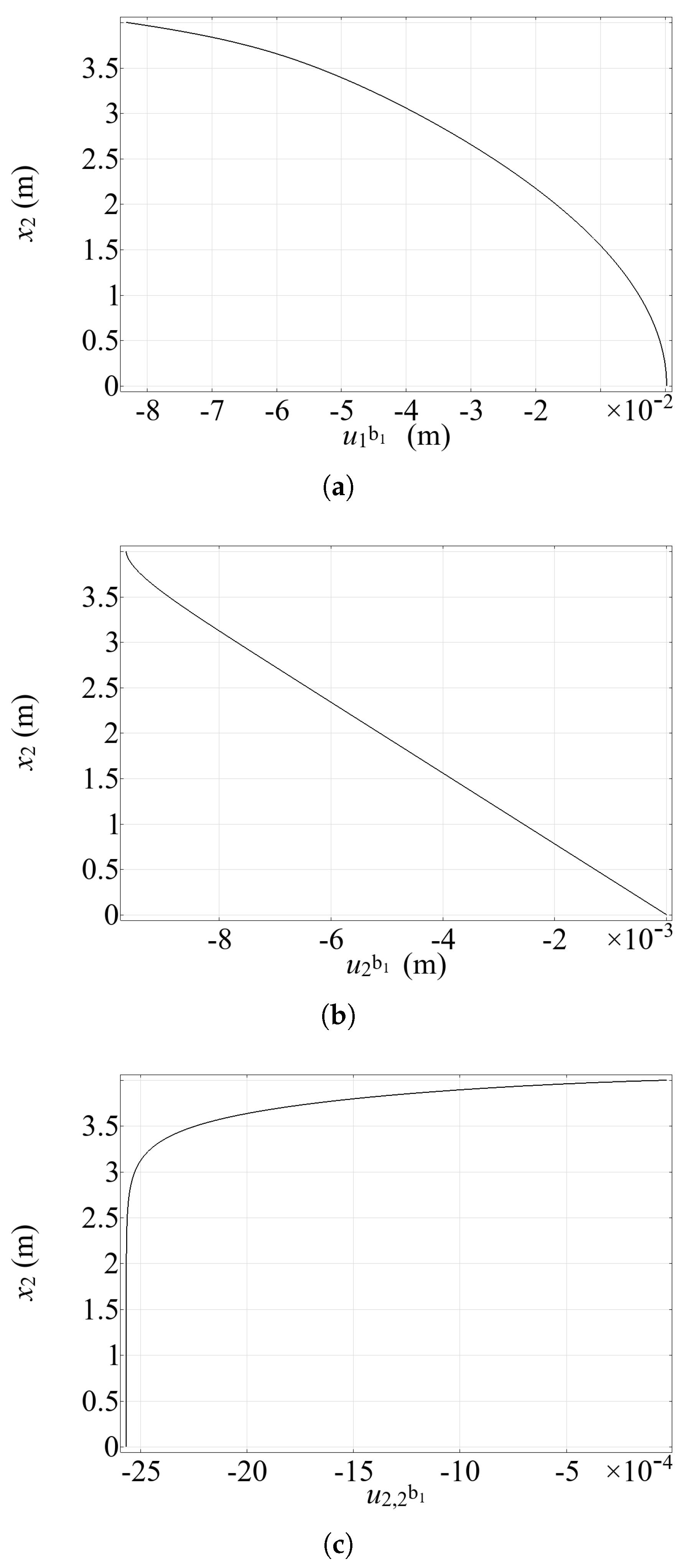
Figure 5 shows the profile of the displacements u 1 b 1 and u 2 b 1 and of the vertical strain component u 2 , 2 b 1 along the vertical interface γ 1 . We recall that in these preliminary simulations, the bending stiffness of the reinforcements is set to zero (i.e., k b n = 0 ). Figure 5a,b depict in turn the profiles of the horizontal and vertical displacements u 1 b 1 and u 2 b 1 along the left vertical interface γ 1 . These plots indicate that the compressive strain of the reinforcement increases progressively from the top to about 2/3 of the height, then remains constant. In particular, Figure 5a reveals that the transverse deformation of the reinforcement (corresponding to the horizontal displacement u 1 ) follows a nonlinear (approximately cubic) profile along γ 1 . Figure 5b,c illustrate the progressive transfer of the compressive loading from the matrix to the left reinforcement, in terms of vertical displacement u 2 b 1 and vertical strain component u 2 , 2 b 1 ( = ε 22 b 1 ) along the line γ 1 . This trend indicates the role of the reinforcements in effectively redistributing stresses and strains within the matrix, contributing to the stability and structural integrity of the system under the applied loading. Notably, localized effects at the reinforcement upper end can be observed.
As we assumed the bending stiffness of the reinforcement beams ( s = 1 , 2 ) k b n s = 0 , the first and third conditions in (14) are identically satisfied. Now, let us consider the second row (14)2. The vertical displacement of the reinforcing beam at the lower end must vanish, i.e., ( u 2 b 1 ) ( x 2 = 0 ) = 0 . Furthermore, due to the presence of arbitrary variations δ u 2 b 1 ( x 2 = h ) , in (14)2 the derivatives ( u 2 b 1 ) ( x 2 = h ) must also vanish. Figure 5 illustrates the profile of the vertical displacement u 2 b 1 along the left vertical interface γ 1 . In Figure 5b one can notice u 2 b 1 ( x 2 = h ) = 0 . This circumstance confirms that the numerical solution provided above is consistent with the analytical boundary conditions deduced by the variational approach outlined in Section 2.2.
Figure 6 shows the distribution of stress components S 11 , S 12 , and S 22 along the horizontal section at the middle height of the structure. In Figure 6a, the normal stress component S 11 in the horizontal direction exhibits a nonlinear trend, with two peaks at the reinforcement location and an almost linear variation in the central region. This behavior reflects the interplay between the matrix deformation and the balancing effect of the reinforcements. Besides, the condition (13)1, which would prescribe a jump at the reinforcement, predicts a continuous response, since the bending stiffness is assumed to vanish. On the contrary, along the middle horizontal section, the tangential stress S 12 exhibits two distinct jumps at the reinforcement locations (interfaces γ 1 and γ 2 ) as shown in Figure 6b, according to the condition (13)2. These discontinuities indicate the redistribution of shear stresses from the matrix to the reinforcements, resulting in a discontinuous and partially mesh-dependent stress profile. Comparing the results provided by different meshes, the stress distribution turns out to be largely consistent throughout most of the structure, with minor variations close to the reinforcements. The stress component S 22 varies linearly along the composite beam cross section, see Figure 6c, consistently with De Saint–Venant theory (at least for the considered parameters).
These preliminary results in terms of displacements, strains, and stresses turn out to be objective if the discretization is sufficiently refined. The stress component S 12 exhibits a slight but irreducible mesh dependency close to the reinforcements, where jumps are met. These findings confirm the reliability and robustness of the computational model.
Our findings are consistent with previous research on stress localization in reinforced composite materials. Among others, Ganguly et al. [47] showed that reinforcement stresses depend strongly on their spatial arrangement, with vertical alignments under load producing the highest stress levels. Similarly, Haque et al. [48] used embedded mechanophores and finite element modeling to demonstrate persistent stress concentrations near fiber reinforcements, even under uniform loading. These studies support our observations of mesh-sensitive stress behavior near reinforcement tips.
Our finite element implementation in COMSOL Multiphysics® 6.0, using Argyris elements and weakly enforced continuity constraints, enhances the smoothness of interface behavior while maintaining robust convergence. Though not benchmarked directly against experiments, our results are consistent with trends reported in the literature. A detailed comparison with gradient models will be explored in future work.

4. Closing Remarks and Future Prospects

In this paper, the equilibrium configuration of a bidimensional structural element with embedded zero-thickness 1D reinforcements has been investigated under small displacements and strains. The matrix was assumed to behave as a first-gradient material, the reinforcement was modeled as an elastic Euler–Bernoulli beam, assuming perfect mutual adhesion between them. Using a variational approach, nontrivial analytical conditions were deduced for both the reinforcements and the surrounding material. Preliminary numerical results were obtained by COMSOL Multiphysics® 6.0 through a symbolic formulation resting on analytical energy density expressions and interface conditions. Weak formulations were discretized by a Galerkin finite element approach, using C 1 continuous Argyris triangular elements for the matrix and Lagrangian quartic elements for the 1D beam. Preliminary simulations were carried out under uniform bending, assuming reinforcing beam elements working as 1D trusses with axial stiffness only. Based on the analyses outlined above, it appears clearly that the reinforcements, although with a purely axial stiffness, are effective in redistributing stresses within the system. Interesting results were obtained for the displacement field along the reinforcements and for the jumps of the shear stress components.
Based on other numerical results not shown herein for brevity, it is worth emphasizing that the analytical conditions deduced from a variational approach were seldom violated at the corners of the rectangular elements, preventing an accurate balance of the stresses at the ends of the reinforcements. Unexpected oscillations resulted at the top or the bottom of the structure for some stress components close to the reinforcements, dependent on the adopted discretization; this phenomenon certainly deserves further investigation. We plan to mitigate such errors using advanced numerical techniques apt to regularize the solution at the corners, or by recourse to alternative theoretical formulations, e.g., a second-gradient modeling of the matrix, which accounts for microstructural effects and can improve the representation of stress distributions in the matrix. In particular, we intend to include higher-order gradient theories, to better describe localized phenomena near the reinforcements and the interfaces.
Building upon the observed stress concentrations near reinforcement tips, future work will explore the application of gradient elasticity theories (second- and third-order). These theories, by incorporating material length scales, provide a promising framework to regularize stress singularities and more accurately capture the localized phenomena and potential size effects evident at the reinforcement-matrix interface investigated here. Furthermore, the computational efficiency demonstrated by the proposed 1D–2D coupling strategy seems to be particularly advantageous for investigating dynamic problems peculiar to several reinforced elements. Future studies will focus on analyzing wave propagation and scattering effects arising from the 1D–2D interface under dynamic loading, and determining how the reinforcement influences the system’s natural frequencies and vibration modes.
The process of remodeling in reinforced systems—analogous to bone remodeling in biological systems—is another direction we plan to investigate, particularly focusing on how material properties and structural adaptations evolve under changing mechanical environments. Our results could contribute to the broader understanding of these processes, as discussed in [49,50], by providing a refined variational perspective and numerical approach to model time-dependent reinforcement-matrix interactions.
Experimental validation remains a critical aspect of our work, and we will try to benchmark and refine our theoretical and numerical findings. Recent literature contributions, e.g., works [51,52], highlight the importance of experimental data in verifying mechanical performance, and we intend to exploit such collaborations to enhance the reliability and applicability of our models in practical engineering scenarios.

Author Contributions

Conceptualization, L.P.; methodology, L.P., A.M. and R.F.; software, A.U.; validation, A.M. and R.F.; formal analysis, L.P.; investigation, A.U. and A.M.; resources, R.L. and F.F.; data curation, A.U.; writing—original draft preparation, A.U.; writing–review and editing, R.F., L.P., A.M. and F.F.; visualization, R.L. and F.F.; supervision, L.P.; project administration, L.P., A.M. and F.F. All authors have read and agreed to the published version of the manuscript.

Funding

This research received no external funding.

Data Availability Statement

The data presented in this study are contained within the article.

Conflicts of Interest

The authors declare no conflict of interest.

References

  1. Hansbo, P.; Larson, M.G. Nitsche’s finite element method for model coupling in elasticity. Comput. Methods Appl. Mech. Eng. 2022, 392, 114707. [Google Scholar] [CrossRef]
  2. Steinbrecher, I.; Mayr, M.; Grill, M.J.; Kremheller, J.; Meier, C.; Popp, A. A mortar-type finite element approach for embedding 1D beams into 3D solid volumes. Comput. Mech. 2020, 66, 1377–1398. [Google Scholar] [CrossRef]
  3. Steinbrecher, I.; Popp, A.; Meier, C. Consistent coupling of positions and rotations for embedding 1D Cosserat beams into 3D solid volumes. Comput. Mech. 2021, 69, 701–732. [Google Scholar] [CrossRef]
  4. Yamamoto, T.; Yamada, T.; Matsui, K. Numerical procedure to couple shell to solid elements by using Nitsche’s method. Comput. Mech. 2019, 63, 69–98. [Google Scholar] [CrossRef]
  5. Shim, K.W.; Monaghan, D.J.; Armstrong, C.G. Mixed Dimensional Coupling in Finite Element Stress Analysis. Eng. Comput. 2002, 18, 241–252. [Google Scholar] [CrossRef]
  6. Klarmann, S.; Wackerfuß, J.; Klinkel, S. Coupling 2D continuum and beam elements: A mixed formulation for avoiding spurious stresses. Comput. Mech. 2022, 70, 1145–1166. [Google Scholar] [CrossRef]
  7. McCune, R.W.; Armstrong, C.G.; Robinson, D.J. Mixed-dimensional coupling in finite element models. Int. J. Numer. Methods Eng. 2000, 49, 725–750. [Google Scholar] [CrossRef]
  8. Monaghan, D.J.; Doherty, I.W.; McCourt, D.; Armstrong, C.G. Coupling 1D beams to 3D bodies. In Proceedings of the International Meshing Roundtable Conference, Dearborn, MI, USA, 26–28 October 1998. [Google Scholar]
  9. Niggl, A.; Düster, A.; Rank, E. Coupling 1D and 2D elasticity problems by using the hp-d-version of the finite element method. In Proceedings of the Second MIT Conference on Computational Fluid and Solid Mechanics, Cambridge, MA, USA, 17–20 June 2003. [Google Scholar]
  10. De Schepper, H. Finite Element Approximation of a 2D–1D Contact Eigenvalue Problem. Numer. Funct. Anal. Optim. 2005, 25, 349–362. [Google Scholar] [CrossRef]
  11. Barretta, R.; Feo, L.; Luciano, R.; Marotti de Sciarra, F. Variational formulations for functionally graded nonlocal Bernoulli–Euler nanobeams. Compos. Struct. 2015, 129, 80–89. [Google Scholar] [CrossRef]
  12. Lu, Y.; Henry, H.S. Numerical modelling of reinforced concrete walls with minimum vertical reinforcement. Eng. Struct. 2017, 143, 330–345. [Google Scholar] [CrossRef]
  13. Horla, D. Variational Calculus Approach to Optimal Interception Task of a Ballistic Missile in 1D and 2D Cases. Algorithms 2019, 12, 148. [Google Scholar] [CrossRef]
  14. Ferreira, D.; Bairán, J.; Antonio Marí, A. Numerical simulation of shear-strengthened RC beams. Eng. Struct. 2013, 46, 359–374. [Google Scholar] [CrossRef]
  15. Pros, A.; Diez, P.; Molins, C. Modeling steel fiber reinforced concrete: Numerical immersed boundary approach and a phenomenological mesomodel for concrete-fiber interaction. Int. J. Numer. Methods Eng. 2012, 90, 65–86. [Google Scholar] [CrossRef]
  16. Belliazzi, S.; Lignola, G.P.; Cosenza, E.; Fabbrocino, F. Non-linear analysis of rectangular cross-sections with different reinforcements: Dimensionless closed form solution. Mater. Struct. 2024, 57, 33. [Google Scholar] [CrossRef]
  17. Dell’Isola, F.; Eremeyev, V.A.; Korolenko, V.A.; Solyaev, Y.O. Deformation of an elastic second gradient spherical body under equatorial line density of dead forces. Eur. J. Mech.-A/Solids 2024, 103, 105153. [Google Scholar] [CrossRef]
  18. Nikabadze, M.U. Splitting of Initial Boundary Value Problems in Anisotropic Linear Elasticity Theory. Mosc. Univ. Mech. Bull. 2019, 74, 103–110. [Google Scholar] [CrossRef]
  19. Wang, F.F.; Dai, H.H.; Giorgio, I. A numerical comparison of the uniformly valid asymptotic plate equations with a 3D model: Clamped rectangular incompressible elastic plates. Math. Mech. Solids 2022, 27, 1370–1396. [Google Scholar] [CrossRef]
  20. Nikabadze, M. On Some Issues of Second Strain Tensor and Velocity Vector Gradient Theories of 3D Bodies and Thin Bodies. Lobachevskii J. Math. 2024, 45, 3683–3706. [Google Scholar] [CrossRef]
  21. Cuomo, M.; dell’Isola, F.; Greco, L. Simplified analysis of a generalized bias test for fabrics with two families of inextensible fibres. Z. Angew. Math. Phys. 2016, 67, 61. [Google Scholar] [CrossRef]
  22. Eremeyev, V.A.; Cazzani, A.; dell’Isola, F. On nonlinear dilatational strain gradient elasticity. Contin. Mech. Thermodyn. 2021, 33, 1429–1463. [Google Scholar] [CrossRef]
  23. Afshar, R.; Jeanne, S.; Abali, B.E. Nonlinear material modeling for mechanical characterization of 3D printed pla polymer with different infill densities. Appl. Compos. Mater. 2023, 30, 987–1001. [Google Scholar] [CrossRef]
  24. Barchiesi, E.; Dell’Isola, F.; Bersani, A.M.; Turco, E. Equilibria determination of elastic articulated duoskelion beams in 2D via a Riks-type algorithm. Int. J. Non-Linear Mech. 2021, 128, 103628. [Google Scholar] [CrossRef]
  25. Barchiesi, E. Multi-scale and multi-physics: Towards next-generation engineering materials. Contin. Mech. Thermodyn. 2020, 32, 541–554. [Google Scholar] [CrossRef]
  26. Stilz, M.; Dell’Isola, F.; Giorgio, I.; Eremeyev, V.A.; Ganzenmüller, G.; Hiermaier, S. Continuum models for pantographic blocks with second gradient energies which are incomplete. Mech. Res. Commun. 2022, 125, 103988. [Google Scholar] [CrossRef]
  27. Eremeyev, V.A.; Dell’Isola, F. On weak solutions of the boundary value problem within linear dilatational strain gradient elasticity for polyhedral Lipschitz domains. Math. Mech. Solids 2022, 27, 433–445. [Google Scholar] [CrossRef]
  28. Nikabadze, M.; Ulukhanyan, A. Some Variational Principles in the Three-Dimensional Micropolar Theories of Solids and Thin Solids. In Theoretical Analyses, Computations, and Experiments of Multiscale Materials. Advanced Structured Materials; Springer: Cham, Switzerland, 2022; Volume 175. [Google Scholar] [CrossRef]
  29. Barchiesi, E.; Harsch, J.; Ganzosch, G.; Eugster, S.R. Discrete versus homogenized continuum modeling in finite deformation bias extension test of bi-pantographic fabrics. Contin. Mech. Thermodyn. 2023, 35, 863–876. [Google Scholar] [CrossRef]
  30. Gazzo, S.; Contrafatto, L.; Greco, L.; Cuomo, M. Anisotropic behaviours and strain concentration in lattice material evaluated by means of discrete homogenization. Mater. Res. Proc. 2023, 26, 517–522. [Google Scholar]
  31. Yang, H.; Timofeev, D.; Giorgio, I.; Müller, W.H. Effective strain gradient continuum model of metamaterials and size effects analysis. Contin. Mech. Thermodyn. 2023, 35, 775–797. [Google Scholar] [CrossRef]
  32. Holler, S.; Butenweg, C.; Noh, S.-Y.; Meskouris, K. Computational model of textile-reinforced concrete structures. Comput. Struct. 2004, 82, 1971–1979. [Google Scholar] [CrossRef]
  33. Turco, E.; Barchiesi, E.; Giorgio, I.; Dell’Isola, F. A Lagrangian Hencky-type non-linear model suitable for metamaterials design of shearable and extensible slender deformable bodies alternative to Timoshenko theory. Int. J. Non-Linear Mech. 2020, 123, 103481. [Google Scholar] [CrossRef]
  34. Mukhopadhyay, S.; Khatana, S. A review on the use of fibers in reinforced cementitious concrete. J. Ind. Text. 2014, 45, 239–264. [Google Scholar] [CrossRef]
  35. Rajak, D.K.; Pagar, D.D.; Menezes, P.L.; Linul, E. Fiber-Reinforced Polymer Composites: Manufacturing, Properties, and Applications. Polymers 2019, 11, 1667. [Google Scholar] [CrossRef] [PubMed]
  36. Lim, D.H.; Oh, B.H. Experimental and theoretical investigation on the shear of steel fibre reinforced concrete beams. Eng. Struct. 1999, 21, 937–944. [Google Scholar] [CrossRef]
  37. Soldatos, K.P. Second-gradient plane deformations of ideal fibre-reinforced materials: Implications of hyper-elasticity theory. J. Eng. Math. 2010, 68, 99–127. [Google Scholar] [CrossRef]
  38. Kant, T.; Gupta, A. A finite element model for a higher-order shear-deformable beam theory. J. Sound Vib. 1988, 125, 193–202. [Google Scholar] [CrossRef]
  39. Fedele, R. Approach à la Piola for the equilibrium problem of bodies with second gradient energies. Part II: Variational derivation of second gradient equations and their transport. Contin. Mech. Thermodyn. 2022, 34, 1087–1111. [Google Scholar] [CrossRef]
  40. Dell’Isola, F.; Seppecher, P.; Placidi, L.; Barchiesi, E.; Misra, A. Least Action and Virtual Work Principles for the Formulation of Generalized Continuum Models. In Discrete and Continuum Models for Complex Metamaterials; Cambridge University Press: Cambridge, UK, 2020; pp. 327–394. [Google Scholar] [CrossRef]
  41. Ricceri, B. A general variational principle and some of its applications. J. Comput. Appl. Math. 2000, 113, 401–410. [Google Scholar] [CrossRef]
  42. dell’Isola, F.; Sciarra, G.; Vidoli, S. Generalized Hooke’s law for isotropic second gradient materials. Proc. R. Soc. A. 2009, 465, 2177–2196. [Google Scholar] [CrossRef]
  43. Seliger, R.L.; Beresford, W.G. Variational principles in continuum mechanics. Proc. R. Soc. Lond. 1968, 305, 1–25. [Google Scholar]
  44. COMSOL, Inc. COMSOL Multiphysics Reference Manual, Version 6.0. Available online: https://doc.comsol.com/6.0/doc/com.comsol.help.comsol/COMSOL_ReferenceManual.pdf (accessed on 30 December 2024).
  45. Kostin, G.; Saurin, V. Analytical derivation of basis functions for Argyris triangle. Z. Angew. Math. Mech. 2001, 81, 127–278. [Google Scholar]
  46. Mohr, G.A. A triangular finite element for thick slabs. Comput. Struct. 1978, 9, 595–598. [Google Scholar] [CrossRef]
  47. Ganguly, P.; Poole, W.J. Influence of reinforcement arrangement on the local reinforcement stresses in composite materials. J. Mech. Phys. Solids 2004, 52, 1355–1377. [Google Scholar] [CrossRef]
  48. Haque, N.; Gohl, J.; Chang, C.C.; Chang, H.C.; Davis, C.S. Quantifying Localized Stresses in the Matrix of a Fiber-Reinforced Composite via Mechanophores. Macromol. Chem. Phys. 2023, 224, 2300298. [Google Scholar] [CrossRef]
  49. Allena, R.; Scerrato, D.; Bersani, A.M.; Giorgio, I. A model for the bio-mechanical stimulus in bone remodelling as a diffusive signalling agent for bones reconstructed with bio-resorbable grafts. Mech. Res. Commun. 2023, 129, 104094. [Google Scholar] [CrossRef]
  50. Tepedino, M.; D’Annibale, F.; Giorgio, I.; Bednarczyk, E.; George, D. Predictive models for bone remodeling during orthodontic tooth movement: A scoping review on the “biological metamaterial” periodontal ligament interface. Contin. Mech. Thermodyn. 2025, 37, 1–17. [Google Scholar] [CrossRef]
  51. Yildizdag, M.E.; Barchiesi, E.; Dell’Isola, F. Three-point bending test of pantographic blocks: Numerical and experimental investigation. Math. Mech. Solids 2020, 25, 1965–1978. [Google Scholar] [CrossRef]
  52. Giorgio, I.; Dell’Isola, F.; Steigmann, D.J. Second-grade elasticity of three-dimensional pantographic lattices: Theory and numerical experiments. Contin. Mech. Thermodyn. 2024, 36, 1181–1193. [Google Scholar] [CrossRef]
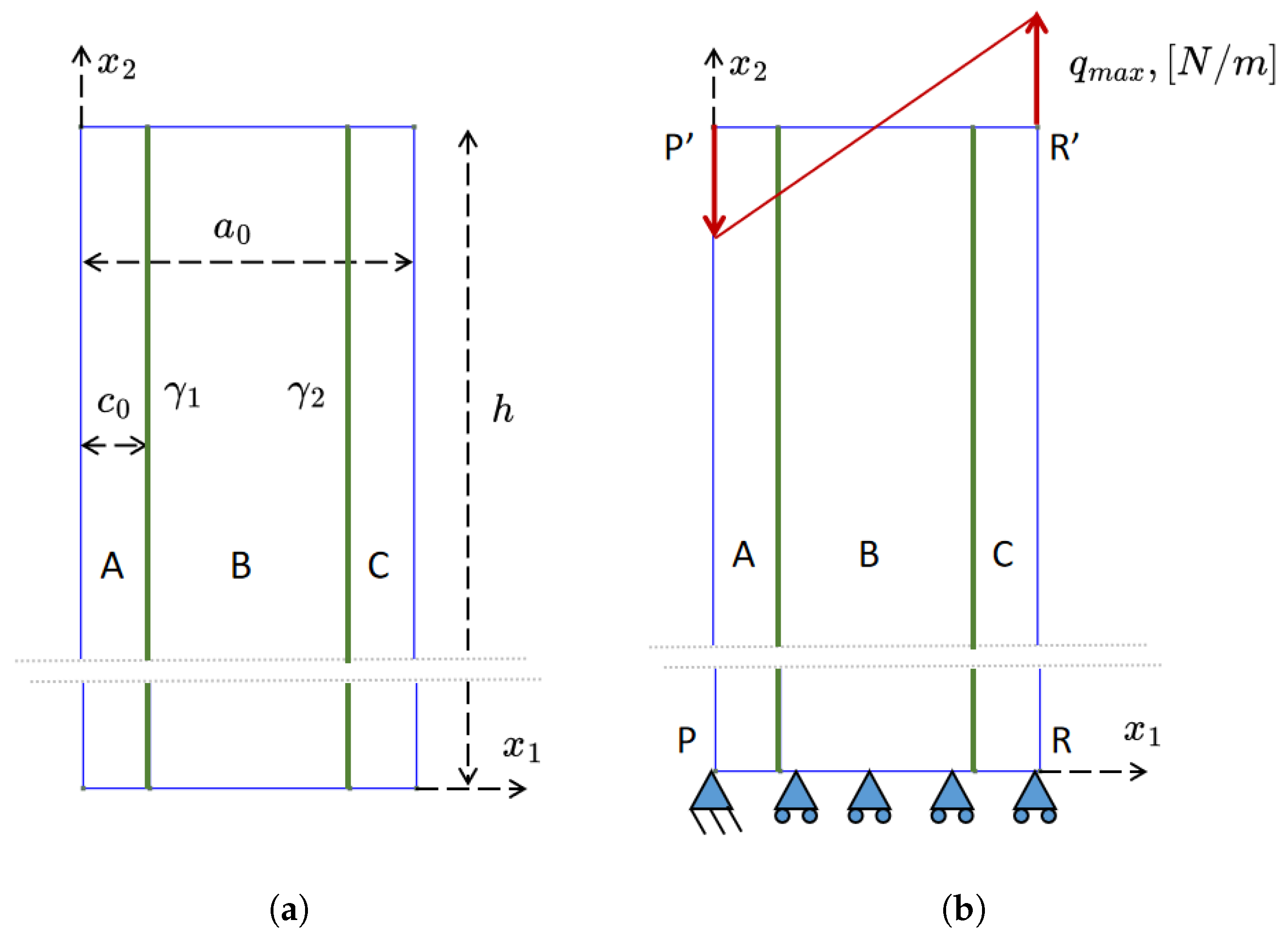
Figure 1. (a) Scheme of the structure under study. The slender structure consists of three rectangular elements referred to as A, B, and C. Two reinforcements are embedded within the structure, represented by the interfaces γ 1 and γ 2 (green lines). The width of A (left domain) and C (right domain) is denoted by the symbol c 0 . The total width is designated as a 0 , and the height is h. (b) The bottom boundary is vertically constrained. The left point of the bottom boundary is fixed. A distributed vertical varying linearly load with a maximum intensity of q m a x is applied along the upper horizontal side of the system. Perfect adhesion is assumed along the interfaces γ 1 and γ 2 .
Fibers 13 00088 g001
Figure 2. Boundaries of rectangular domains A, B, and C, as referenced in the variational deduction of governing equations and boundary conditions (12). Note that the sides Q Q , M M and N N , L L coincide, respectively, with the interfaces γ 1 and γ 2 .
Fibers 13 00088 g002
Figure 3. (a) Finite element mesh used for the simulation of the 2D reinforced elastic structure. (b) The deformed mesh (magnified × 100) under uniform bending, with the bottom boundary constrained isostatically. This deformed configuration is relevant to the case where with bending stiffness k b n is null, and the axial stiffness k a x = 1.28 · 10 11 N.
Fibers 13 00088 g003
Figure 4. Displacement and vertical strain along horizontal sections at the top ( x 2 = h ) and middle height ( x 2 = 0.5 h ), obtained with the fine mesh. Reinforcement locations are indicated by dashed vertical lines at x 1 = c 0 and x 1 = a 0 c 0 . (a,b) The distribution of u 1 and u 2 along the horizontal top boundary (with x 2 = h ). Symmetrical profile of u 1 with inflection points demonstrates the influence of reinforcement stiffness. Antisymmetric profile of u 2 with sharp peaks near reinforcements, indicating high localized deformation. (c) The distribution of u 1 along the horizontal middle line ( x 2 = 0.5 h ). Parabolic profile consistent with classical beam bending theory. (d,e) The vertical displacement u 2 and vertical strain u 2 , 2 ( = ε 22 ) distributions along the middle horizontal line ( x 2 = 0.5 h ). Linear distribution, matching classical elasticity predictions for bending in this region.
Fibers 13 00088 g004
Figure 5. Displacement and vertical strain profiles characterizing the behavior within the left reinforcement, as emphasized by the superscript b, along the (left) vertical interface γ 1 . (a) Horizontal displacement u 1 b 1 . Cubic profile illustrating the reinforcement’s transverse deformation. (b) Vertical displacement u 2 b 1 . Shows the axial displacement variation along the reinforcement length. (c) Vertical strain u 2 , 2 b 1 = ε 22 b 1 . Demonstrates the progressive build-up of compressive axial strain from top to bottom, indicating effective load transfer from the matrix to the reinforcement.
Fibers 13 00088 g005
Figure 6. Distribution of the stress components along the horizontal section at middle height x 2 = 0.5 h . Reinforcement locations are indicated by dashed lines. (a) Normal stress component S 11 along the horizontal direction. Nonlinear profile with peaks near reinforcements, highlighting stress concentration and matrix-reinforcement interaction. (b) Shear stress S 12 which exhibits mesh dependency close to the reinforcement. Exhibits distinct jumps at the reinforcement interfaces, consistent with the derived variational condition (13). (c) Normal stress component S 22 along the horizontal direction. Shows an approximately linear distribution consistent with far-field classical bending predictions.
Fibers 13 00088 g006
Table 1. Features of the selected discretizations.
Mesh TypeElements Along InterfacesDegrees of FreedomNodes (Total/Interface)
Coarse Mesh5626206337/68
Medium Mesh192227,2501412/112
Fine Mesh8002205,00410,641/840
Disclaimer/Publisher’s Note: The statements, opinions and data contained in all publications are solely those of the individual author(s) and contributor(s) and not of MDPI and/or the editor(s). MDPI and/or the editor(s) disclaim responsibility for any injury to people or property resulting from any ideas, methods, instructions or products referred to in the content.