Highlights
- What are the main findings?
- A nonlinear finite element model was developed to simulate the structural behavior of cellular cross-laminated timber (CCLT) using Hill’s yield criterion and Hashin’s damage criterion in Abaqus.
- In bending simulations, the Hashin model yielded highly accurate predictions, with deviations of 0.2% for long-span and 1% for short-span beams. The Hill model showed good performance as well, with a 7–9% error for long-span and 8% for short-span bending, depending on the element configuration.
- Both models successfully predicted failure modes: tensile failure in the lumber under long-span bending and shear failure in the corrugated core under short-span bending.
- In rolling shear tests, the Hill model underestimated the maximum shear load by 11%, while the Hashin model showed a larger deviation of 26%.
- What is the implication of the main finding?
- The validated models provide reliable tools for predicting CCLT performance, particularly under bending loads, offering insights into failure mechanisms critical for structural design.
- Despite underestimations in rolling shear simulations, both Hill and Hashin criteria demonstrate strong potential for further development and application in advanced CCLT modeling.
- These findings contribute to optimizing CCLT panel design, supporting more efficient and resilient timber structures in sustainable construction.
Abstract
This study investigates the structural performance of cellular cross-laminated timber (CCLT) through a nonlinear finite element model using Hill and Hashin damage criteria in Abaqus. This study evaluates these criteria in simulating CCLT’s mechanical behavior under bending and shear loading. Experimental validation included short-span and long-span bending tests, along with rolling shear tests. In bending simulations, the Hill criterion predicted maximum loads with a 7% error for long-span beams when modeling lumber as solid elements and the corrugated panel as shell elements. When the entire CCLT was modeled using shell elements, the error increased to 9%. For the short-span bending, the error remained at 8% regardless of element type. The Hashin model provided more accurate results, with deviations of 0.2% for long-span beams and 1% for short-span beams. Both models successfully predicted failure mechanisms, identifying tension failure in the lumber under long-span bending and shear failure in the corrugated core under short-span bending. In rolling shear tests, the Hill criterion underestimated the maximum shear load by 11%, while the Hashin criterion had a larger underestimation of 26%. Despite these discrepancies, both models effectively captured the nonlinear behavior of CCLT panels. These findings highlight the potential of Hill and Hashin criteria for modeling CCLT’s mechanical response, offering valuable insights into structural design applications.
1. Introduction
In contemporary construction, cross-laminated timber (CLT) has become a ground-breaking engineered wood product that provides a sustainable substitute for conventional materials like steel and concrete [1,2]. CLT has emerged as a key component of modern mass timber construction due to its exceptional mechanical qualities, environmental credentials, and adaptability, especially in high-rise and large-span buildings [3]. The potential of employing low-value lumber from small-diameter trees, hardwoods, recycled wood, and composite materials has been investigated in recent studies exploring creative options for manufacturing CLT panels. Cellular cross-laminated timber (CCLT) is a potential innovation that utilizes wood strand-based corrugated panels and the benefits of cellular structures to create lightweight structural solutions, making use of small-diameter trees [4]. Experimental and computational parametric studies have been carried out to assess the influence of various geometric factors, offering insights into improving CCLT structural performance. However, to understand the overall performance and predict the load-carrying capacity of these CCLT panels, the integration of nonlinear approaches in the modeling technique is needed. The modeling of CCLT is highly complex due to its multi-component structure, which consists of lumber in the outer layers and a corrugated panel core in the middle layer. This complexity arises from the distinct mechanical properties of the materials, as both the lumber and corrugated panel core exhibit orthotropic behavior, with varying strengths and stiffness in different directions.
The nonlinear behavior of wood can be modeled using three main approaches: elastic-plastic, elastic-damage, and combined elastic-plastic-damage models [5]. Elastic-plastic models utilize yield criteria to capture permanent deformation beyond the elastic limit [5,6]. These models are suitable for applications where plasticity dominates but do not account for stiffness degradation caused by damage. In contrast, elastic-damage models employ damage variables to simulate stiffness degradation due to microcracking and fiber separation [7]. These models employ damage variables and anisotropic damage evolution laws to reflect timber’s directional properties, making them ideal for predicting material degradation and failure under cyclic or long-term loading. However, they do not include plastic deformation. The most comprehensive approach combines elastic-plastic and damage models, incorporating both plasticity and stiffness degradation [8]. This combined approach can accurately represent timber’s complex behavior under various loading conditions, including cyclic loads. These models often use orthotropic formulations to account for wood’s behavior. While this combined approach offers the most accurate representation of timber behavior, it is computationally intensive and requires extensive material calibration and validation.
Traditional elastic-plastic nonlinear modeling often relies on yield criteria that fall short of capturing the anisotropic yield behavior of wood. Hill’s anisotropic yield criterion, an extension of the von Mises criterion, addresses this limitation by accounting for directional yielding. It has become widely adopted for modeling timber behavior under diverse loading conditions. Researchers have employed Hill’s criterion with anisotropic hardening to describe the nonlinear elastic-plastic behavior of timber, particularly its compressive response [9,10,11]. Although Hill’s criterion does not distinguish between tension and compression strengths, it offers significant practical advantages, including a reduced number of required parameters and improved numerical convergence. This efficiency facilitates direct integration into finite element (FE) software like Abaqus, enabling the accurate 3D modeling of wood elements under bending [12]. Hill’s criterion is widely used for assessing damage initiation due to its robustness. However, it is well-suited for monotonic loads, such as those encountered in static bending tests, but lacks the capability to model damage progression, making it less effective for regions with concentrated stresses.
In contrast, the Hashin damage criterion, an elastic-damage model, is widely used for predicting damage in fiber-reinforced composites [13]. This model distinguishes between fiber and matrix damage modes, offering a more detailed representation of damage mechanisms compared to traditional criteria like the maximum stress or strain theories. This criterion uses quadratic stress polynomials expressed in terms of transversely isotropic invariants of the applied average stress state [14]. This approach separates damage modes based on whether the damage occurs in the fibers or the matrix, using distinct equations to reflect the physical failure mechanisms typically observed in composites. This criterion, originally developed for unidirectional fibrous composites, is valued for its straightforward and physically meaningful approach, producing continuous convex surfaces for each failure mode. As an interactive damage criterion, the Hashin model accounts for the combined effects of multiple interacting stresses, making it particularly suitable for complex materials like fiber-reinforced polymers [15]. Unlike traditional models, the Hashin criterion distinguishes between tension and compression strengths in different directions and accounts for varying fracture energy values, making it particularly suited for materials like wood. Previous research analyzing plywood under tension showcased the versatility of the Hashin criterion in FE modeling for investigating progressive failure. This approach helped optimize plywood lay-ups and provided a computationally efficient tool for simulating compact tension tests [16].
Despite the promising performance of CCLT structures, a nonlinear finite element (FE) model capable of capturing the deformation of such CLT structures with a corrugated transverse layer has not yet been developed. Such a model could significantly enhance the design process of CCLT structures and improve the prediction of their load-carrying capacity. This study evaluates the applicability and accuracy of two distinct failure criteria—Hill’s yield criterion and the Hashin damage criterion—in predicting the strength of CCLT panels under bending and rolling shear. By employing Abaqus FE software, this research offers a novel approach to assessing material damage in CCLT panels. This study enhances the understanding of CCLT behavior, providing valuable insights into their load-carrying capacity and helping to optimize design applications.
2. CCLT
2.1. Manufacturing
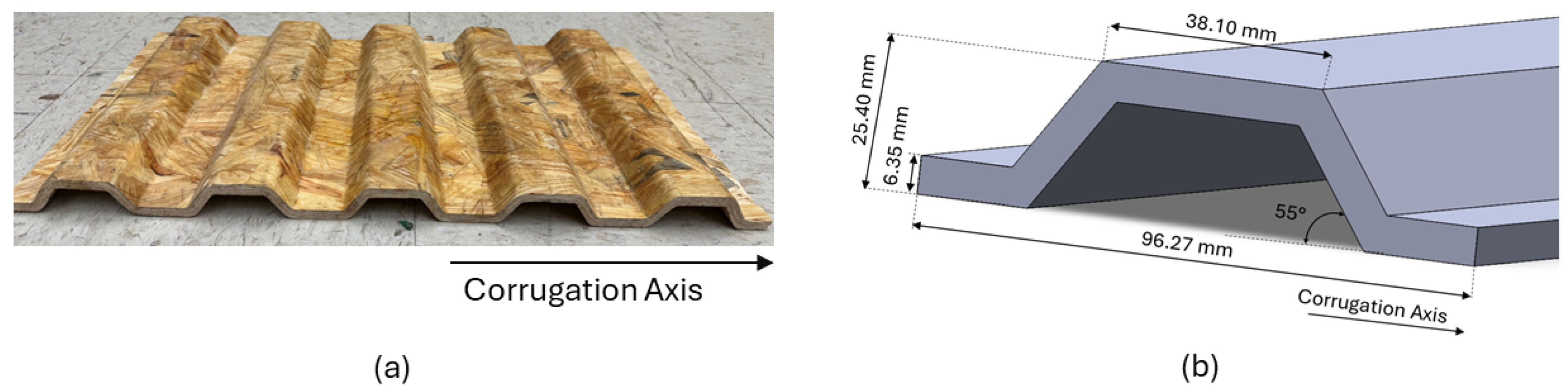
The corrugated panels were fabricated using commercially available wood strands with a moisture content of 8–10%. These strands were blended in a drum blender with polymeric methylene diphenyl diisocyanate (pMDI) resin, applied at 11% of the strands’ oven-dry weight. The resin-coated strands were manually aligned using an orientor, ensuring they were parallel to the corrugation axis, which is also parallel with principal axis 1. The wood strand mat was then hot-pressed in a mold for 5 min, forming a corrugated geometry with a target density of 800 kg/m3, following the geometric dimensions specified in the study conducted by Pradhan et al. (2024) [4]. The corrugated panel, along with the corrugation axis representing the direction of wood strands, is shown in Figure 1.
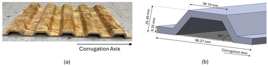
Figure 1.
(a) Corrugation panel and corrugation axis; (b) geometrical details of the unit cell in the corrugated panel.
To fabricate CCLT, the corrugated panel was sandwiched between dimensional lumber (2 × 6, no. 2 grade loblolly pine). To ensure optimal bonding, the surfaces of the lumber and the corrugated panels were planed and sanded, respectively, and then treated with a Loctite PR 3105 PURBOND primer at a concentration of 5% by weight, applied at 20 g/m2. The layers were bonded using a Loctite HB X602 PURBOND polyurethane adhesive at an application rate of 180 g/m2. The assembly was subjected to a pressing force of 0.7 N/mm2 for eight hours. CCLT specimens for these tests were fabricated individually, rather than being cut from a panel.
2.2. Experimental Testing
CCLT specimens were evaluated under bending and rolling shear tests, as the bending load is a primary force in various applications, and shear stress is maximized at the mid-plane of CCLT specimens where the corrugated panels are placed.
2.2.1. Bending Test
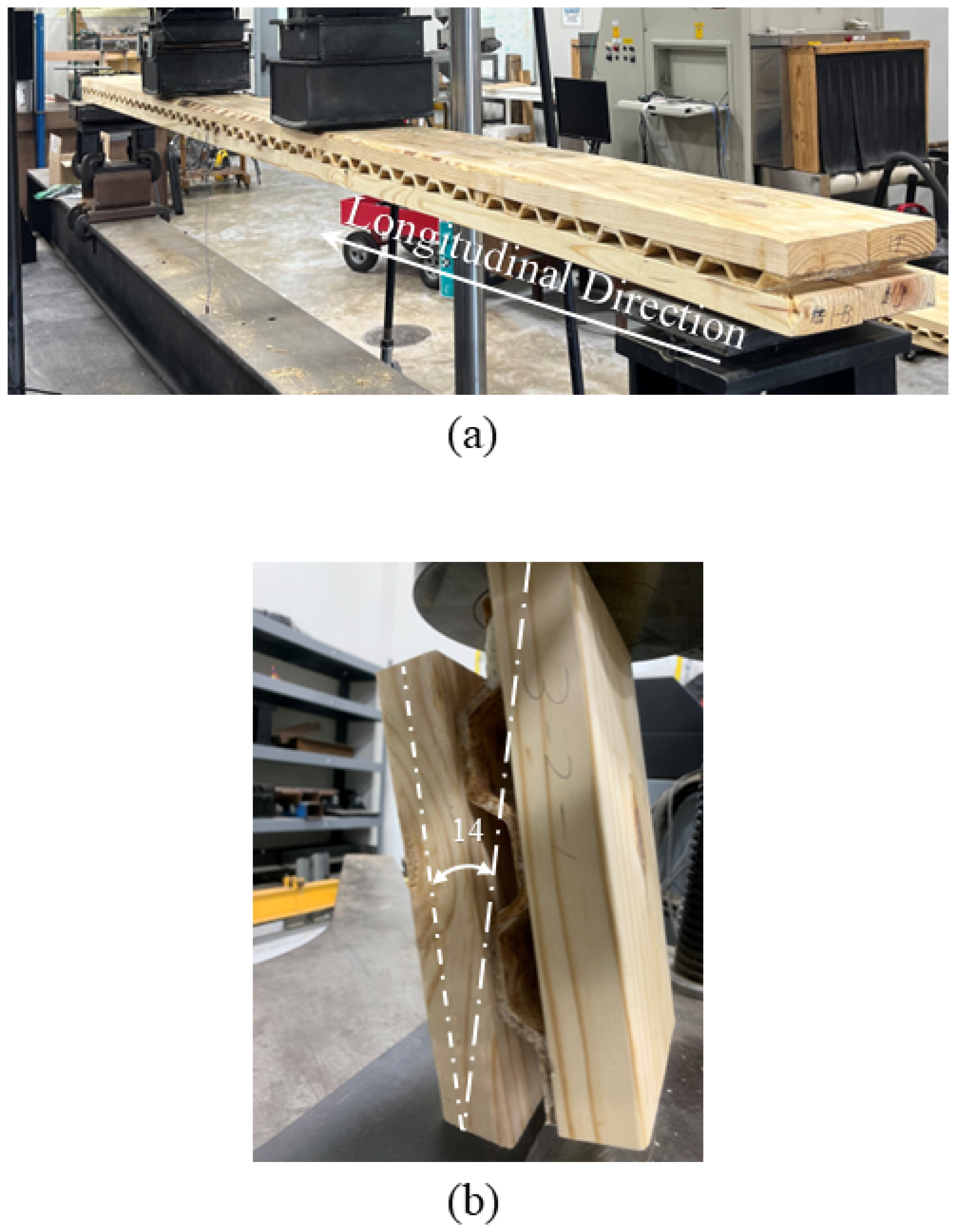
Bending samples were subjected to a static four-point bending test (third point), with loads at one-third of the span length following ASTM D198 standards, to evaluate their bending performance, as shown in Figure 2a. Two types of bending specimens were prepared: long-span and short-span bending specimens. The long-span bending specimens had a span-to-depth ratio of 23, with a span length of 2336 mm and a width of 254 mm. In contrast, the short-span bending specimens had a span-to-depth ratio of 13, with a span length of 1219 mm and a width of 270 mm. Two specimens were tested for each span length. The flexural stiffness (EI) of the CCLT beam was calculated using Equation (1).
where
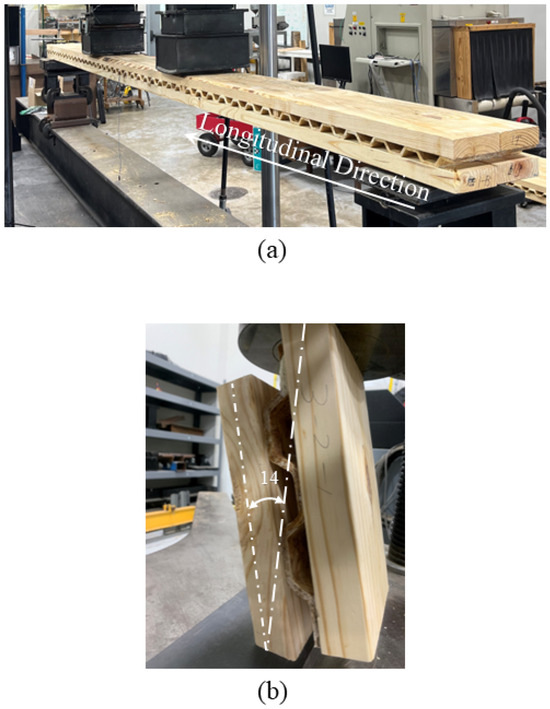
Figure 2.
(a) Four-point (third point) bending test; (b) rolling shear test.
P = applied bending load;
S = span length of CCLT;
a = distance between the load and support (S/3 in this study);
Δ = mid-span deflection;
P/Δ = slope of the load vs. deflection curve in the linear region.
2.2.2. Rolling Shear Test
Rolling shear samples were fabricated using corrugated panels, with dimensions of 127 mm in width and 228 mm in length. To obtain a more accurate understanding of the shear performance of CCLT, this length was selected to include two-unit cells under the shear load, as shown in Figure 2b. The inclination angle for rolling shear specimens was 14 degrees. The compressive load path was aligned through the geometric center of the corrugated panel core to avoid creating torque and to ensure a uniform shear stress distribution across the corrugated panel, facilitating reliable and consistent results essential for accurately determining their structural performance.
2.3. Constitutive Model
In this study, material principal axes were defined using the local 1-2-3 coordinate system to accurately capture the orthotropic behavior of wood-based materials. The details of the coordinate system adopted are explained in Section 2.4.
2.3.1. Elastic Behavior
Linear elasticity has been defined as an orthotropic material, which includes the three elastic moduli (E1, E2, E3), the Poisson’s ratios (ν12, ν13, ν23), and the shear moduli (G12, G13, G23) associated with the material’s principal axes. These constants define the material’s elastic compliance, as described by Equation (1), following Hooke’s Law [17].
Here, the terms σ11, σ22, and σ33 are the principal stresses, while σ12, σ13, and σ23 represent the shear stress components.
2.3.2. Nonlinear Behavior
Hill Criteria: Elastoplastic Model
Constitutive equations play a critical role in analyzing the behavior of elastoplastic materials under various loading conditions. These equations establish relationships between stress, incremental strain, and other internal variables [18]. Below a critical stress level, materials typically undergo elastic deformation, transitioning to elastoplastic behavior once the threshold is surpassed [19]. This transition is marked by a smooth yet distinct change in the material’s response [20]. Hill’s criterion has been applied to model the elastoplastic behavior in this study. The reference yield stress was used to evaluate lumber under tension and the corrugated panel core under compression. The material behavior was modeled using the Hill yield criterion, which accounts for orthotropic plasticity. Once the stress state satisfies the Hill criterion, plastic deformation occurs, leading to strain hardening. This approach enables the model to accurately represent peak load behavior based on the failure stress, as the material continues to exhibit plastic strain even beyond the yield point.
Hill’s stress function is defined as follows:
where, F, G, H, L, M, and N are constants that characterize the material’s orthotropic properties obtained by tests of the material in different orientations, defined as follows:
Here, the terms σ11, σ22, and σ33 are the principal stresses, while σ12, σ13, and σ23 represent the shear stress components. is the reference yield stress and (i = 1, 2, 3; j = 1, 2, 3) is the strength of the material in tension/compression and shear. The plastic strain () was determined using the associated flow rule, given by the following:
where, = .
Hashin Criteria: Elastic Damage Model
The failure initiation in the Hashin criterion accounts for fiber and matrix failures, incorporating four distinct failure modes:
- (1)
- Fiber tension (), ( 0)
- (2)
- Fiber compression (), ( 0)
- (3)
- Matrix tension (), ( 0)
- (4)
- Matrix compression (), 0)
The post-damage behavior of materials, which is a damage evolution model, has been modeled using a damaged elasticity matrix, which reflects the degradation of material stiffness as damage accumulates during loading. The original elasticity matrix of the undamaged material was modified by a damage variable in each direction, reflecting the material’s degradation due to damage. The damaged elasticity matrix Ed was calculated as follows:
where E is the original elasticity matrix, and d represents the damage variable.
Ed = (1 − d) E
The damage variable is a scalar parameter used in continuum damage mechanics to quantify the degradation of material stiffness due to microstructural damage, such as cracking, void formation, or fiber breakage [17,21]. It ranges from 0 (no damage) to 1 (complete failure), modifying the material stiffness matrix to reflect the progressive loss in load-carrying capacity. In this study, the damage variable evolves based on the stress–displacement response, ensuring that the total energy dissipated corresponds to the material’s critical fracture energy. Damage initiates when the equivalent stress reaches a threshold, and further deformation leads to a gradual reduction in load-bearing capacity. To enhance numerical stability in nonlinear finite element simulations, a viscous regularization technique is applied, introducing a small damping coefficient (0.01) to prevent abrupt force drops that could cause convergence issues. This approach ensures a smoother transition in the damage evolution process, improving computational robustness.
2.4. FE Model
The nonlinear behavior of CCLT was analyzed using the 2023 version of the Abaqus FE software [17]. The performance and accuracy of the nonlinear models were subsequently validated through comparisons with experimental tests. In the first simulation, third-point bending tests were conducted for short-span and long-span configurations. These analyses validated the accuracy of the nonlinear models in predicting the flexural behavior of CCLT. The second simulation focused on rolling shear tests to assess and validate these models’ accuracy in capturing the shear response of CCLT. These validation steps ensure the reliability of the developed models in replicating the mechanical behavior of CCLT under various loading conditions.
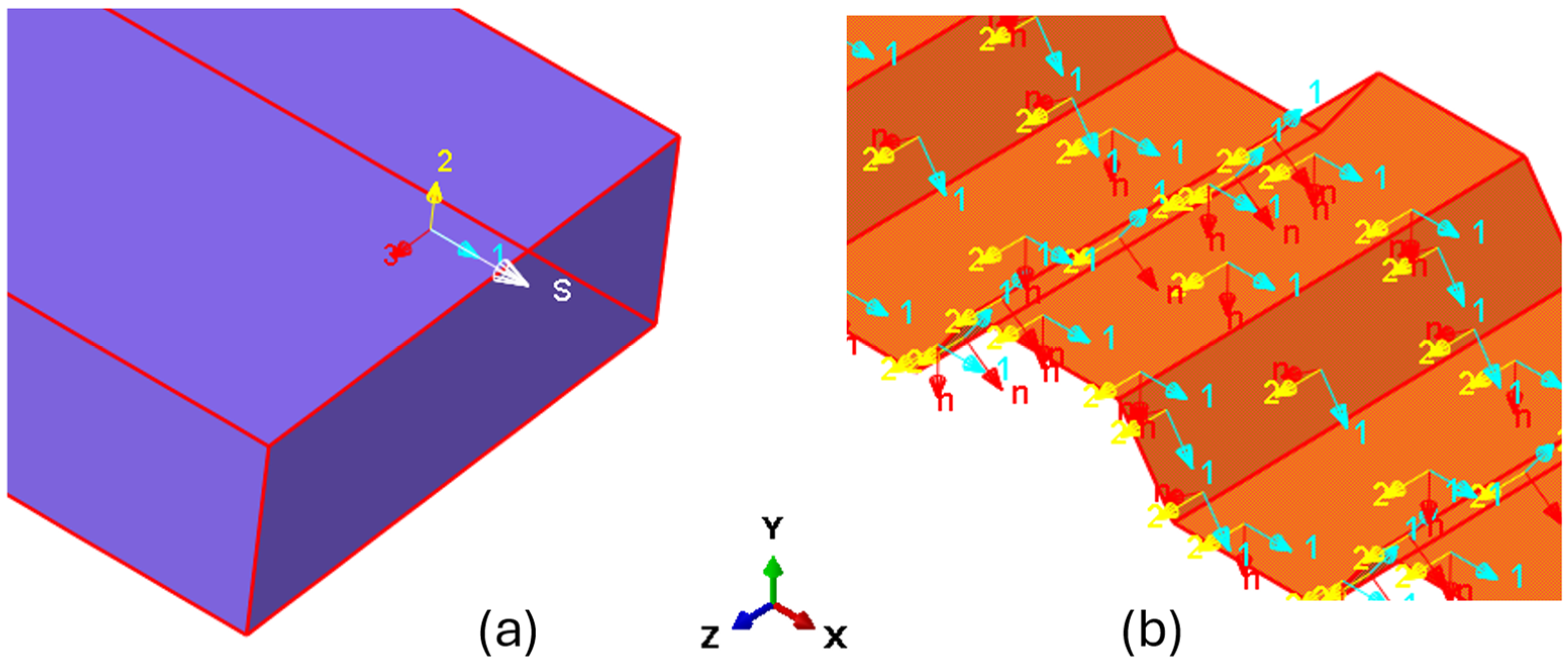
For the lumber, axis 1 was assigned along the longitudinal direction (parallel to the grain), axis 2 along the radial direction (perpendicular to the grain), and axis 3 along the tangential direction (aligned with the growth rings), as shown in Figure 3a. In the case of the corrugated panel, axis 1 was aligned with the strand direction, while axis 2 and axis 3 were assigned to the transverse and thickness directions of CCLT, respectively, as shown in Figure 3b. These local material orientations were implemented in Abaqus to ensure that the orthotropic mechanical properties and strength properties were correctly represented in the finite element simulations.

Figure 3.
Definition of local axes for the FEM model: (a) lumber and (b) corrugated panel.
For this study, both elastic and strength material properties were adopted from the existing literature for the relevant materials. For modeling the lumber, the longitudinal elastic modulus was adopted from Wright et al. (2019) [22] for loblolly pine, while the remaining elastic properties were determined using the elastic ratios and Poisson’s ratios provided in the Wood Handbook [23] for the same species. The elastic properties of the corrugated panel core were obtained from Mohammadabadi and Yadama (2020) [24]. Strength properties were sourced from Doyle and Markwardt (1967) [25] for the lumber and Zhu et al. (2005) [26] for the corrugated panel. Fracture energy values required for implementing the Hashin damage were derived from Malek et al. (2019) [27] for the corrugated panel core and Ivanov and Sadowski (2009) [16] for the outer lumber. All the required material properties are presented in Table 1.

Table 1.
Material properties for FE modeling.
2.4.1. Bending Test Model
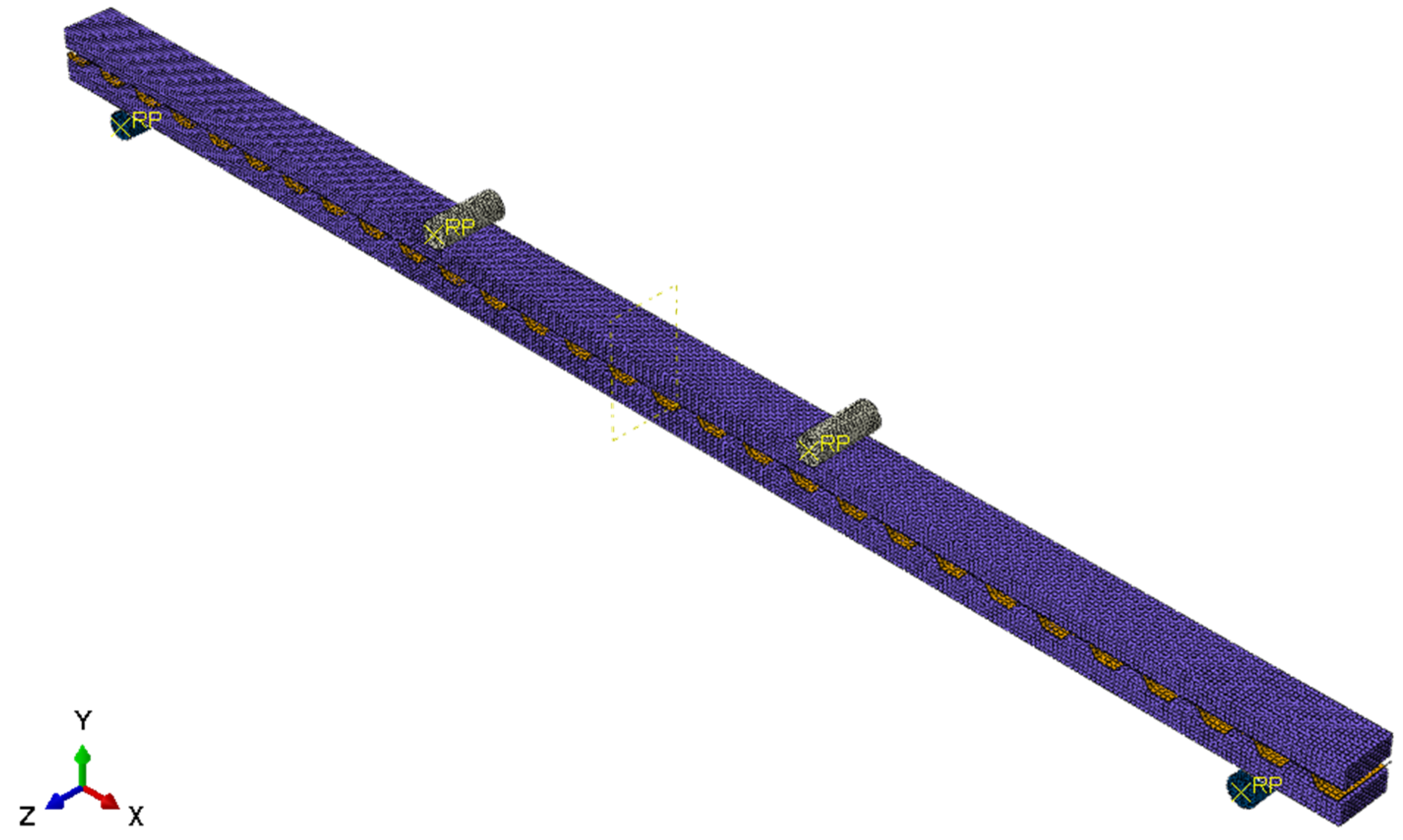
To better understand the bending behavior of CCLT, both long-span and short-span bending tests were modeled. Similar to the experimental test, a rigid cylindrical body was used to simulate the support and loading head, as shown in Figure 4. The boundary conditions were defined by applying an “Encastre” constraint to the cylindrical support, fully restricting all degrees of freedom. To apply bending deflection, a displacement-controlled test was simulated by imposing a constant vertical displacement in the Y direction on the top cylindrical rigid bodies, representing the loading head. The contact interactions between the lumber and the cylindrical rigid bodies were defined considering both the normal and transverse directions relative to the contact surface. The normal direction refers to the direction perpendicular to the contact surface (Y direction), where a “Hard” pressure–overclosure relationship was applied, allowing only compressive contact without penetration under loading. The transverse directions (X and Z) are tangential directions to the contact surface, where a frictional contact formulation was implemented. To simulate resistance to sliding between the surfaces, a static coefficient of friction of 0.3 was assigned in these tangential directions.
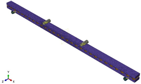
Figure 4.
Finite element model of four (third)-point test with mesh size of 8 mm.
In Abaqus, the Hashin damage failure criterion can only be applied to shell elements, requiring shell elements for both the outer lumber layers and corrugated panel core. S4R elements were used for both components in this Hashin criterion. These S4R elements are bilinear quadrilateral shell elements designed to capture both bending and membrane behavior effectively. As four-node doubly curved elements with reduced integration and hourglass control, they prevent numerical instabilities, making them ideal for analyzing thin-walled components. To maintain geometric accuracy, the shell elements were positioned at the mid-surface offset.
Unlike the Hashin criterion, the Hill criterion offers more flexibility, as it can be implemented using either solid or shell elements. This versatility allowed for the development of two distinct modeling approaches. The first approach, designated as the Hill-Solid-Shell approach, utilized C3D8R elements (eight-node hexahedral solid elements) for the outer lumber layers and S4R shell elements for the corrugated panel core. The second approach, designated as the Hill-Shell-Shell approach, employed S4R shell elements for both the outer lumber layers and the corrugated panel core. This consistent element usage in the Hill-Shell-Shell model facilitated a direct comparison with the Hashin criterion model, while eliminating element-type variables.
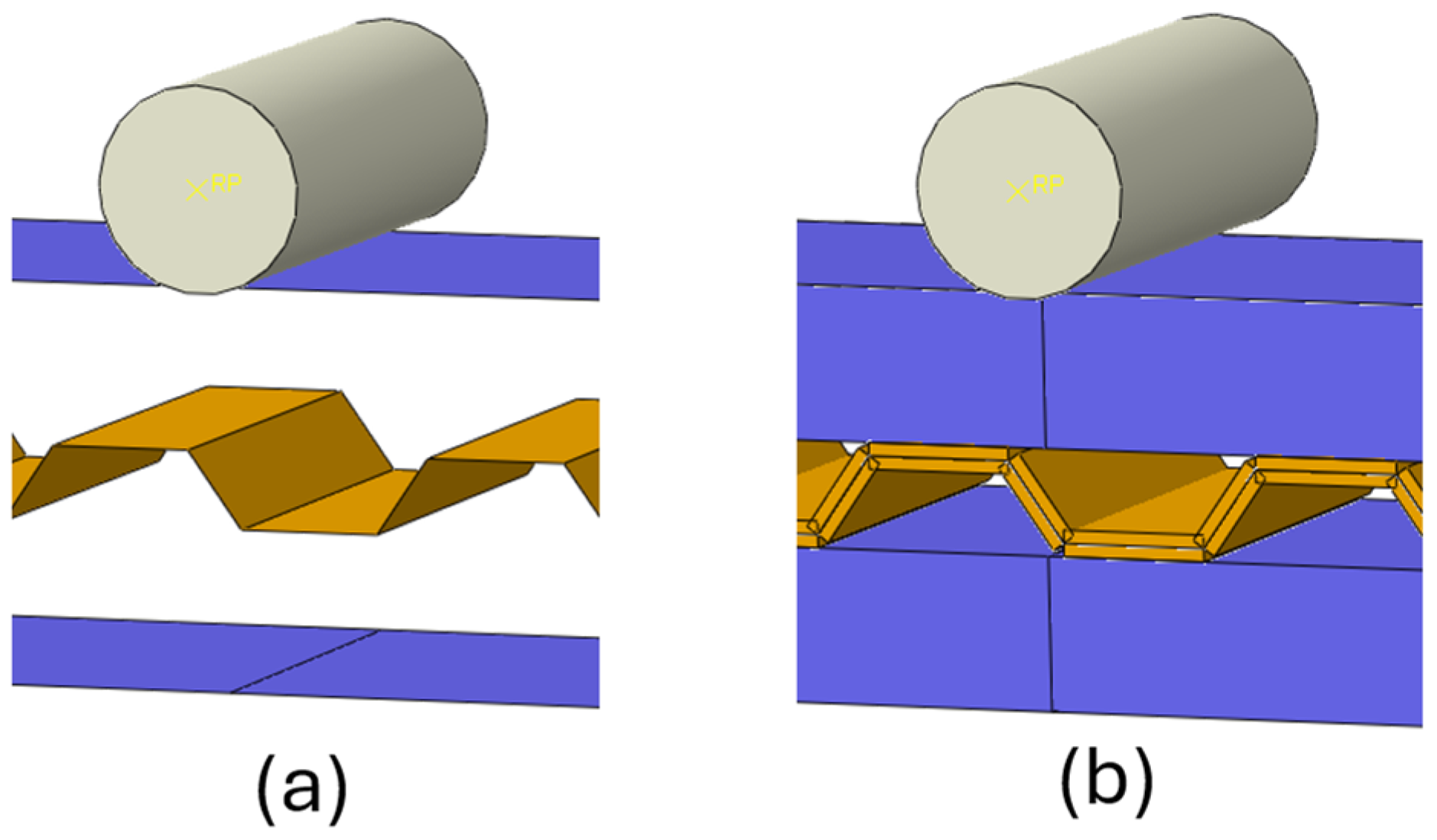
For models constructed entirely with shell elements (both Hill-Shell-Shell and Hashin criterion), the shell elements were strategically positioned at the outermost layer of the lumber to ensure proper contact with the rigid cylindrical elements, while for the corrugated panel core, they were positioned at the mid-layer, as illustrated in Figure 5. This configuration guaranteed realistic contact behavior and enhanced the accuracy of the simulated structural response.
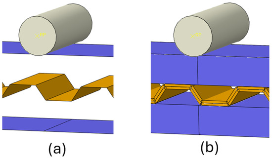
Figure 5.
CCLT panel (a) modeled using shell elements for both the lumber and the corrugated panel and (b) rendered shell thickness.
In the Hill-Solid-Shell model, the outer lumber layers were represented using C3D8R elements, which are specifically designed for 3D solid materials in Abaqus. These elements utilize reduced integration to improve computational efficiency and incorporate hourglass control to prevent spurious deformation modes, ensuring an accurate representation of the lumber’s volumetric mechanical behavior [11]. The corrugated panel core was modeled using S4R elements.
A mesh sensitivity analysis with varying mesh sizes was conducted to discretize lumber and the corrugated panel for the Hill-Solid-Shell case. A tie constraint was implemented at the contact surface between the corrugated panel core and lumber to achieve perfect bonding. Adhesives typically have high shear performance and provide secure and effective bonding between wood products. This tie constraint was selected to reflect the strong bond and ensure that no glue line failure occurs between the lumber and the core layer. The reaction load and displacement at the mid-span were recorded and plotted to evaluate the structural performance and to compare with the experimental results.
2.4.2. Rolling Shear Test Model
The FE model was developed to replicate the modified rolling shear test with the objective of evaluating the deformation and load-carrying capacity of CCLT specimens under shear load. The simulation used rigid circular plates to represent both the test bed and the loading head. The test bed plate was assigned an “Encastre” boundary condition, fully constraining all degrees of freedom. A constant vertical displacement was applied to the loading plate. The contact interactions between the lumber and the rigid plates were defined similarly to those in the bending test, addressing both normal and transverse directions. In the normal direction (Y direction) shown in Figure 6, a “Hard” pressure–overclosure relationship was applied to prevent penetration at the contact surface. For the transverse directions (X and Z directions), a frictional contact model with a static coefficient of friction of 0.3 was used to simulate sliding resistance. The rolling shear test focused on the shear behavior of the mid-layer, ensuring that the outer layers remained within their elastic limits due to their higher stiffness in compression parallel to the grain. The outer lumber layers were assigned elastic material properties, whereas the mid-layer was characterized by nonlinear material behavior, incorporating both the Hill yield criterion and the Hashin damage model. The outer lumber layers were discretized using C3D8R elements, while the corrugated panel core was modeled using S4R elements. The mesh size was consistent with that used in the bending test, which was determined through a prior mesh analysis.
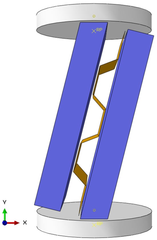
Figure 6.
FE model for rolling shear test.
3. Results and Discussion
To provide a comprehensive evaluation of the nonlinear model, the results and discussion are organized into two sub-sections: the third point bending test, which examines the flexural performance of CCLT panels, and the rolling shear test, which evaluates the shear behavior of the mid-layer corrugated panel. The FE results predicting the load-carrying capacity are presented using both the Hill and Hashin nonlinear methods.
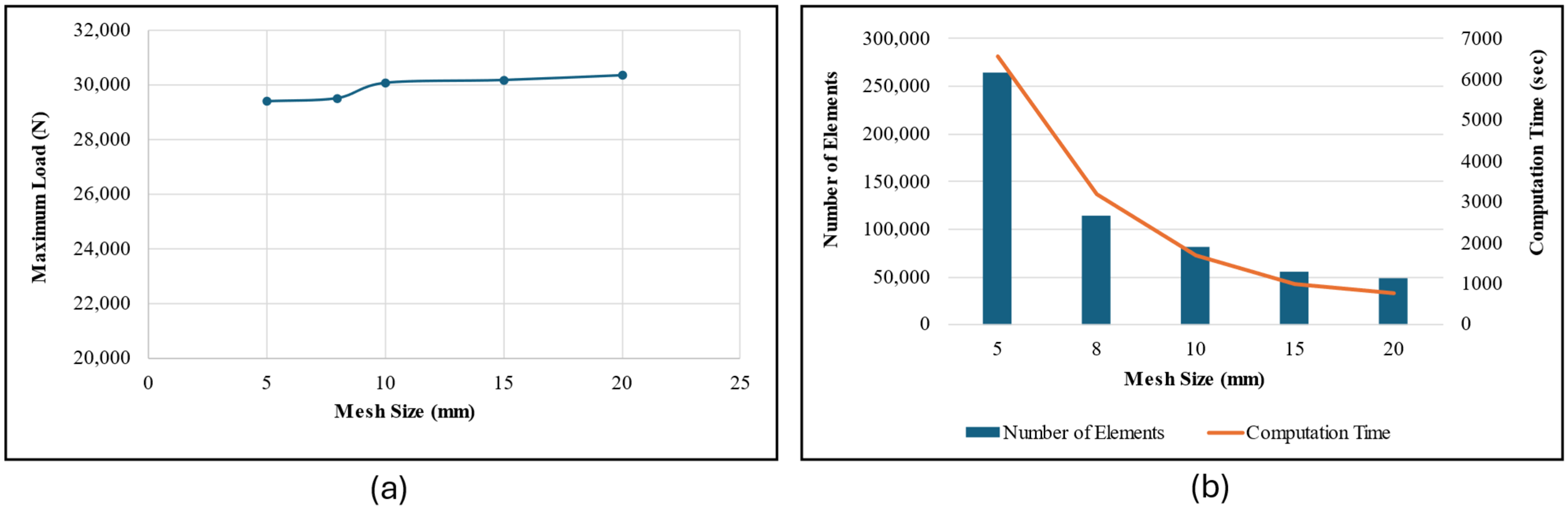
A mesh convergence analysis was conducted on the long-span bending CCLT modeled with solid elements for the lumber and shell elements for the corrugated panel using the Hill criterion to determine the optimal element size. The analysis results, illustrated in Figure 7a, show the relationship between the mesh size and the maximum bending load. As the mesh was refined, the variation in the bending load became negligible, with only a 0.39% difference observed between the 8 mm and 5 mm meshes. The total number of elements ranged from 48,951 for a 20 mm mesh to 115,007 for an 8 mm mesh, and 265,151 for a 5 mm mesh, as shown in Figure 7b. Additionally, the computational time was significantly reduced from 6567 s for the 5 mm mesh to 3200 s for the 8 mm mesh. Considering the minimal change in bending load and the substantial reduction in computational cost, an 8 mm mesh was selected for all FE models, as shown in Figure 4.

Figure 7.
(a) Maximum predicted load vs. mesh size; (b) number of elements and computation time for respective mesh sizes.
3.1. Third Point Bending Result
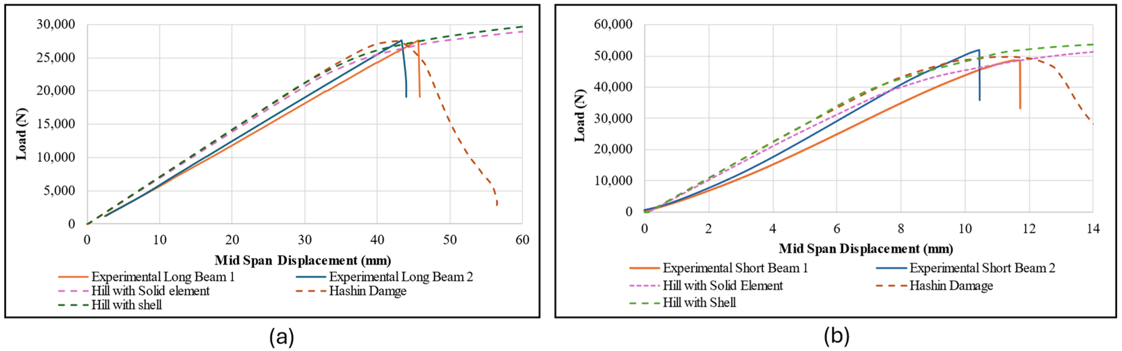
The bending load versus mid-span displacement curves of long-span and short-span CCLT beams modeled using Hill and Hashin criteria are compared with the experimental results, as shown in Figure 8 and Figure 9, respectively. Additionally, a summary of bending stiffness values, calculated using Equation (1), and the maximum load is presented in Table 2.
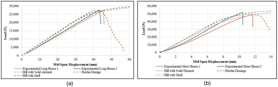
Figure 8.
Load versus mid-span displacement of (a) long-span bending of CCLT; (b) short-span bending of CCLT.

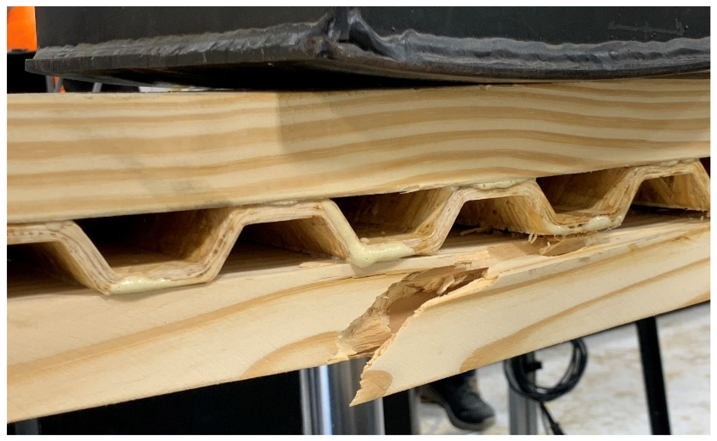
Figure 9.
Experimentally observed failure mode in long span bending of CCLT.
Table 2.
Comparison of bending stiffness and maximum load between numerical models and experimental result.
The slope of the linear region in the load–displacement curves obtained from the FE model showed good agreement with experimental results. The bending stiffness of long-span CCLT between the FE model and experimental data differed by 5% using the Hill-Solid-Shell model and 7% using the Hill-Shell-Shell and Hashin damage models. Similarly, for short-span bending, the differences were 6% for the Hill-Solid-Shell model and 11% for Hill-Shell-Shell and Hashin damage models.
While consistent material properties contribute to similarity in the linear region, the choice of element type also plays a measurable role in bending stiffness. Specifically, the Hill criterion, when applied with different element configurations (Hill-Solid-Shell vs. Hill-Shell-Shell), produces slight variations in results, indicating that element selection influences the structural response even within the elastic range. On the other hand, models using the same element type (Hill-Shell-Shell and Hashin) exhibit similar behavior, despite relying on different failure criteria. This suggests that the type of element used may have a greater impact on bending stiffness than the specific failure model applied.
Regardless of the element type—whether solid or shell—the FE model of CCLT using the Hill criterion exhibited a plateau region due to plastic yielding, where the load continued to increase steadily since no explicit failure criterion was applied. In the case of the Hill criterion, the failure of the beam in nonlinear materials is defined as the point at which the maximum principal stress exceeds the material’s strength limit. To determine the failure point, the maximum principal stress is monitored at each time step throughout the simulation. Failure is considered to occur at the time step immediately preceding the moment when the maximum principal stress exceeds the material’s strength limit.
Compared to the experimental results, the maximum bending load predicted by the Hill-Solid Shell model differed by 7%, while the Hill-Shell-Shell model showed a 9% difference for long-span CCLT beams. Similarly, for short-span bending, the difference was 8% for both Hill-Solid-Shell and Hill-Shell-Shell models. In contrast, the Hashin damage criterion provided a more accurate prediction of the maximum load, with deviations of only 0.2% for long-span beams and 1% for short-span beams compared to the experimental results. The load–displacement response of CCLT beams modeled with Hashin damage exhibited a sharp decline beyond failure, attributed to the progressive degradation of the stiffness matrix. This degradation results from the fracture energy dissipation during failure, effectively capturing the post-peak behavior of the material. The Hashin model provides a more realistic representation of failure mechanisms, as it incorporates stiffness reduction due to damage initiation and propagation. This response highlights the FE model’s ability to simulate the transition from elastic and plastic phases to failure, offering valuable insights into CCLT’s structural performance. The steep drop in the load–displacement curve reinforces the importance of incorporating fracture energy in numerical modeling to accurately simulate post-failure behavior.
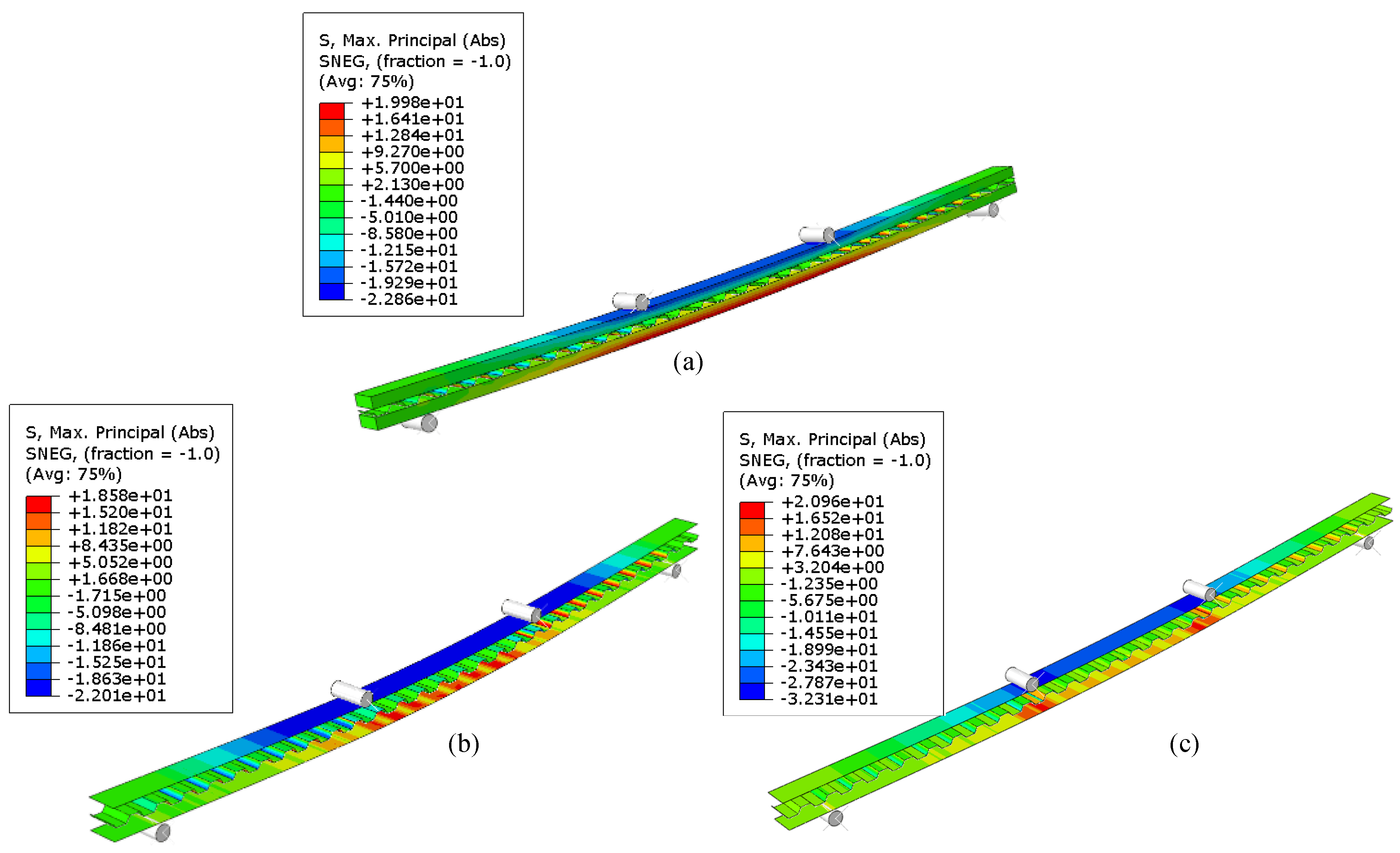
Long-span CCLT failed due to tension in the bottom lumber under the bending load, as shown in Figure 9. The distribution of maximum principal stress in long-span CCLT modeled using different mesh types and failure criteria is shown in the Figure 10. For beams modeled using the Hill criterion, failure was evaluated manually based on the stress values exceeding or reaching the defined strength of the lumber and corrugation materials. The maximum principal stress in CCLT beams modeled using the Hill criterion reached the defined strength of the lumber at the maximum load values, which is presented in Table 2. Beyond this point, the stress exceeded the material’s capacity, marking the onset of failure. In contrast, failure in the Hashin damage model occurred when the specific Hashin damage criterion was met (as mentioned in Hashin Criteria: Elastic Damage Model), as indicated by a reduction in the bending load, shown in Figure 8a. Notably, the Hashin model predicted a lower bending load at failure compared to the Hill criterion.

Figure 10.
Maximum principal stress (in MPa) at failure of FE models for long span bending test; (a) Hill-Solid-Shell model; (b) Hill-Shell-Shell model; and (c) Hashin Damage model.
Short-span CCLT beams exhibited shear failure in the corrugated panel core, as shown in Figure 11, with stress distribution illustrated in Figure 12. The FE models consistently captured this behavior, considering failure to occur when the maximum principal stress reached the material’s strength limit. The Hashin model again predicted failure at a lower bending load than the Hill criterion, emphasizing the differences in their failure evaluation mechanisms. The Hill criterion, as a yield-based approach, predicted higher load capacities, whereas the Hashin model, incorporating progressive damage mechanics, yielded more conservative failure loads.
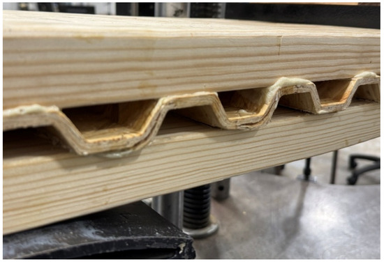
Figure 11.
Experimentally observed failure mode in short span bending of CCLT.
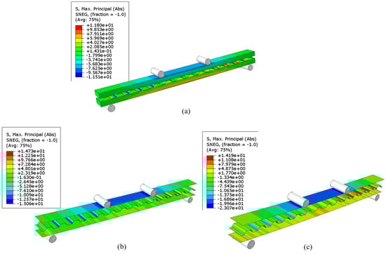
Figure 12.
Maximum principal stress (in MPa) at failure of FE models for short span bending test; (a) Hill-Solid-Shell model; (b) Hill-Shell-Shell model; and (c) Hashin Damage model.
The observed failure modes—tensile failure in long-span beams and shear failure in short-span beams—align with expected stress distributions, reinforcing the validity of all three FE models in predicting structural response.
3.2. Rolling ShearTest Result
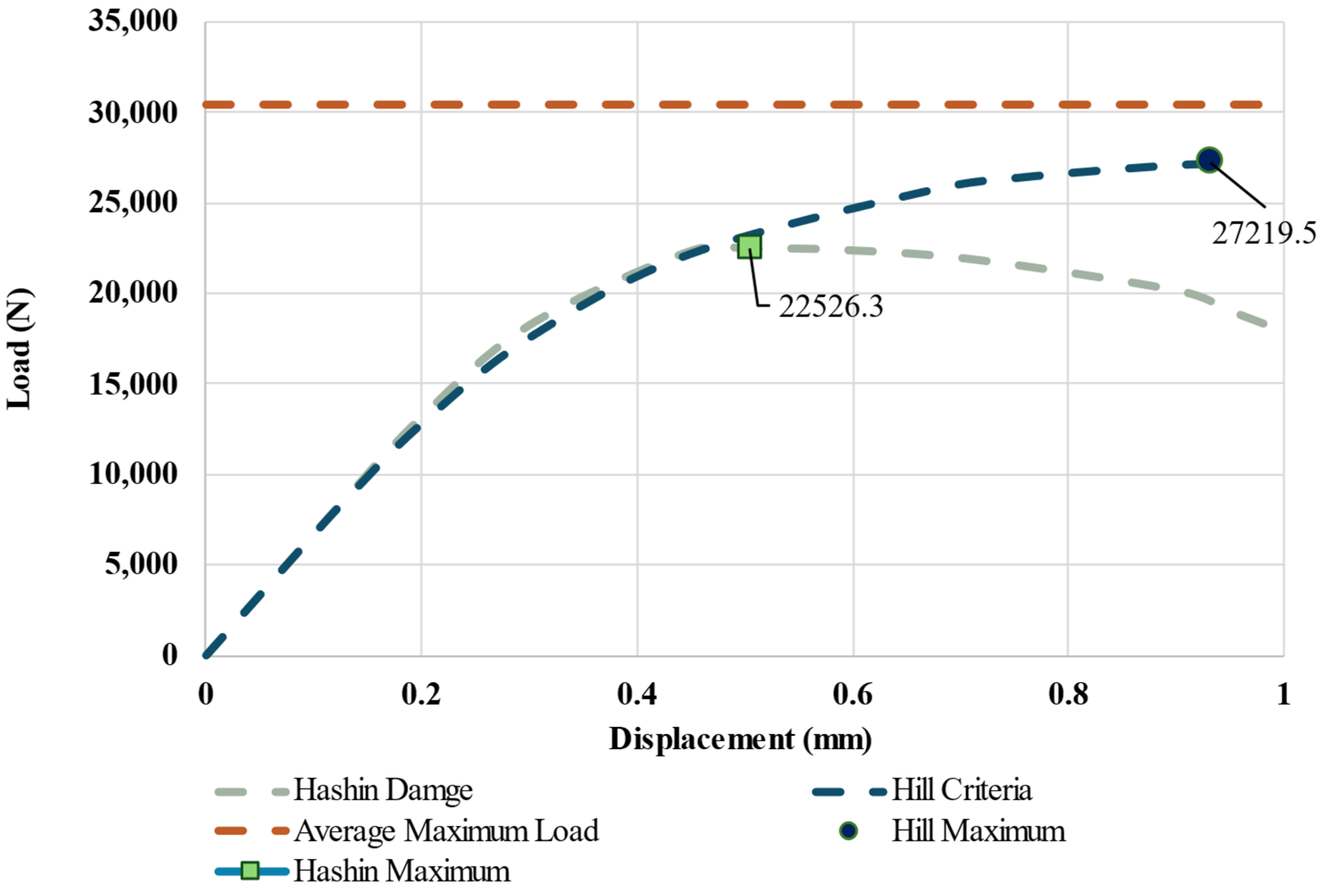
The load–displacement response of the top loading plate was recorded and compared across two failure criteria, as shown in Figure 13. A horizontal line indicating the average maximum load obtained from the experimental rolling shear test is included for reference, along with the load–displacement curves of FE models. Both models were conservative and underestimated the maximum shear load, with the Hill criterion showing an error of 11% below the experimental average, while the Hashin damage criterion exhibited a larger underestimation, with an error of 26%—consistent with previous findings where the Hashin model predicted a lower load capacity. These findings emphasize differences in predictive accuracy between the two criteria.

Figure 13.
Load versus top plate displacement of FE model in rolling shear test and average maximum shear load from experiment.
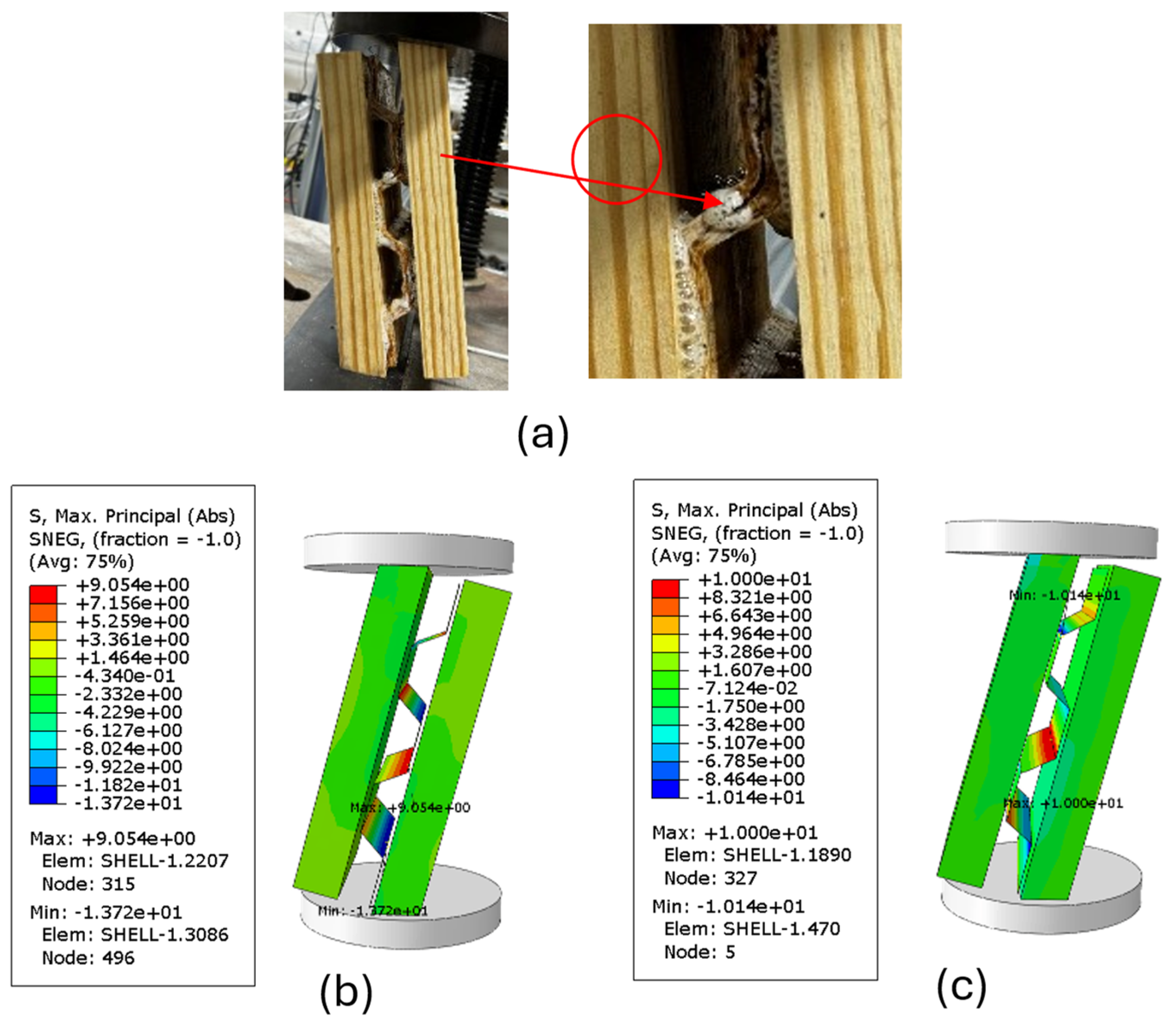
The shear failure in the corrugated panel core during the experiment (Figure 14a) was successfully captured by both the Hill criterion and Hashin damage model. The Hashin damage model predicted an ultimate failure load of 22,526 N as the maximum principal stress was 10 MPa, whereas in the Hill criterion was 13.72 MPa under 27,219 N before failure, as shown in Figure 14b,c. This result is consistent with the bending models. Despite predicting different failure loads, both models effectively replicate the experimental failure mode.
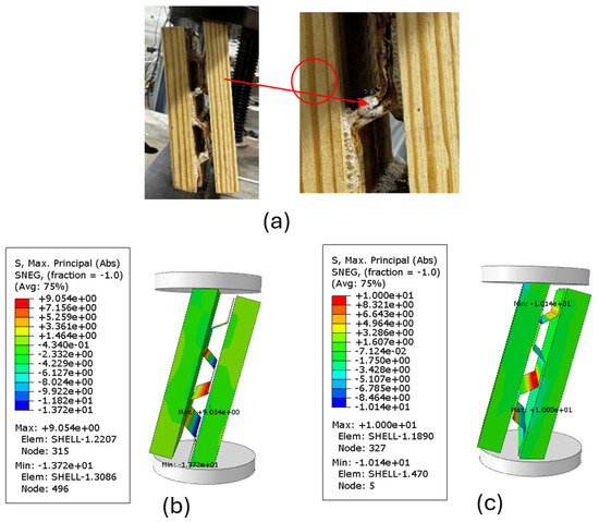
Figure 14.
(a) Experimentally observed failure mode in rolling shear test; (b) maximum principal stress (in MPa) at failure of FE models for Hill’s criterion; and (c) maximum principal stress (in MPa) at failure of FE models for Hashin damage.
4. Conclusions
The primary objective of this study was to develop and validate a nonlinear FE model for CCLT panels using Hill’s yield criterion and the Hashin damage criterion to predict their performance under bending and rolling shear loads. The nonlinear behavior of CCLT panels was analyzed using Abaqus FE software, and simulations were validated against experimental tests for short-span and long-span bending, as well as rolling shear tests.
The bending test models demonstrated high accuracy within the elastic range and effectively captured the failure mechanisms of CCLT beams. In long-span bending, the Hill criterion showed deviations of 7% and 9% for models using Hill-Solid-Shell (solid elements for lumber and shell elements for the corrugated panel), and Hill-Shell-Shell (all shell elements) models, respectively, while the Hashin damage model with shell elements exhibited a minimal deviation of 0.2%. For short-span bending, the Hill criterion with both Hill-Solid-Shell and Hill-Shell-Shell models resulted in an 8% error, whereas the Hashin model provided a closer prediction, with only a 1% deviation. Both approaches accurately identified failure locations, with tensile failure in the lumber layers for long-span beams and shear failure in the corrugated core for short-span beams. However, in rolling shear tests, the Hill criterion underestimated the maximum shear load by 11%, while the Hashin model showed a larger deviation of 26%, indicating the need for further refinement in predicting shear behavior.
This study advances nonlinear modeling techniques for CCLT panels and highlights the applicability of Hill’s and Hashin’s criteria in structural simulations. The findings provide valuable insights into failure mechanisms and offer a basis for optimizing CCLT design to enhance performance in sustainable construction. Future work should prioritize the experimental evaluation of material properties to enhance the accuracy and reliability of the models. These efforts will further support the development of efficient and robust CCLT systems for structural applications.
Author Contributions
Conceptualization, S.P. and M.M.; methodology, S.P. and M.M.; validation, S.P. and M.M.; formal analysis, S.P. and M.M.; investigation, S.P. and M.M.; resources, M.M.; data curation, S.P. and M.M.; writing—original draft preparation, S.P.; writing—review and editing, M.M.; visualization, S.P. and M.M.; supervision, M.M.; project administration, M.M.; funding acquisition, M.M. All authors have read and agreed to the published version of the manuscript.
Funding
This material is based upon work supported by McIntire-Stennis, accession number 7003668, and is a contribution of the Forest and Wildlife Research Center, Mississippi.
Data Availability Statement
The raw data supporting the conclusions of this article will be made available by the authors upon request.
Acknowledgments
We would like to express our sincere gratitude to Henkel, West Fraser, Hexion, and Huntsman for generously providing the materials necessary for this study.
Conflicts of Interest
The authors declare no conflicts of interest.
References
- Harte, A.M. Mass timber—The emergence of a modern construction material. J. Struct. Integr. Maint. 2017, 2, 121–132. [Google Scholar] [CrossRef]
- Younis, A.; Dodoo, A. Cross-laminated timber for building construction: A life-cycle-assessment overview. J. Build. Eng. 2022, 52, 104482. [Google Scholar] [CrossRef]
- Wang, Z.; Yin, T. Cross-Laminated Timber: A Review on Its Characteristics and an Introduction to Chinese Practices. In Engineered Wood Products for Construction; IntechOpen: London, UK, 2021. [Google Scholar]
- Pradhan, S.; Mohammadabadi, M.; Seale, D. Quantifying the effect of profile design on flexural stiffness in cellular cross-laminated timber: A numerical exploration and experimental verification. Mater. Struct. 2024, 57, 164. [Google Scholar] [CrossRef]
- Eslami, H.; Jayasinghe, L.B.; Waldmann, D. Nonlinear three-dimensional anisotropic material model for failure analysis of timber. Eng. Fail. Anal. 2021, 130, 105764. [Google Scholar] [CrossRef]
- Xu, B.-H.; Bouchaïr, A.; Racher, P. Appropriate Wood Constitutive Law for Simulation of Nonlinear Behavior of Timber Joints. J. Mater. Civ. Eng. 2014, 26, 4014004. [Google Scholar] [CrossRef]
- Sirumbal-Zapata, L.F.; Málaga-Chuquitaype, C.; Elghazouli, A.Y. Plasticity-damage material constitutive model for timber subjected to cyclic loading. In Proceedings of the 16th World Conference on Earthquake, Santiago, Chile, 9–13 January 2017; Volume 1122. [Google Scholar]
- Wang, M.; Song, X.; Gu, X. Three-Dimensional Combined Elastic-Plastic and Damage Model for Nonlinear Analysis of Wood. J. Struct. Eng. 2018, 144. [Google Scholar] [CrossRef]
- Kharouf, N.; McClure, G.; Smith, I. Elasto-plastic modeling of wood bolted connections. Comput. Struct. 2003, 81, 747–754. [Google Scholar] [CrossRef]
- Moses, D.M.; Prion, H.G.L. Stress and failure analysis of wood composites: A new model. Compos. B Eng. 2004, 35, 251–261. [Google Scholar] [CrossRef]
- Oudjene, M.; Khelifa, M. Elasto-plastic constitutive law for wood behaviour under compressive loadings. Constr. Build. Mater. 2009, 23, 3359–3366. [Google Scholar] [CrossRef]
- Kawecki, B.; Podgórski, J. 3D Abaqus Simulation of Bent Softwood Elements. Arch. Civ. Eng. 2020, 66, 323–337. [Google Scholar] [CrossRef]
- Echaabi, J.; Trochu, F.; Gauvin, R. Review of failure criteria of fibrous composite materials. Polym. Compos. 1996, 17, 786–798. [Google Scholar] [CrossRef]
- Hashin, Z. Failure Criteria for Unidirectional Fiber Composites. J. Appl. Mech. 1980, 47, 329–334. [Google Scholar] [CrossRef]
- Christensen, R.M. A Survey of and Evaluation Methodology for Fiber Composite Material Failure Theories. In Mechanics for a New Mellennium; Springer: Dordrecht, The Netherlands, 2001. [Google Scholar]
- Ivanov, I.V.; Sadowski, T. Numerical modelling and investigation of plywood progressive failure in CT tests. Comput. Mater. Sci. 2009, 45, 729–734. [Google Scholar] [CrossRef]
- Manual, Abaqus Analysis User’s Guide. Abaqus 6.11. 89(2080), v6. 2012. Available online: http://130.149.89.49:2080/v2016/books/usb/default.htm (accessed on 1 January 2024).
- Bodner, S.R.; Partom, Y. Constitutive Equations for Elastic-Viscoplastic Strain-Hardening Materials. J. Appl. Mech. 1975, 42, 385–389. [Google Scholar] [CrossRef]
- Sivák, P.; Frankovský, P.; Delyová, I.; Bocko, J.; Kostka, J.; Schürger, B. Influence of Different Strain Hardening Models on the Behavior of Materials in the Elastic–Plastic Regime under Cyclic Loading. Materials 2020, 13, 5323. [Google Scholar] [CrossRef]
- Bernstein, B.E. A unified theory of elasticity and plasticity. Int. J. Eng. Sci. 1977, 15, 645–660. [Google Scholar] [CrossRef]
- Shrestha, J.K.; Pradhan, S.; Gautam, D. In-plane behavior of various brick bonds in masonry walls. Innov. Infrastruct. Solut. 2020, 5, 58. [Google Scholar] [CrossRef]
- Wright, S.; Dahlen, J.; Montes, C.; Eberhardt, T.L. Quantifying knots by image analysis and modeling their effects on the mechanical properties of loblolly pine lumber. Eur. J. Wood Wood Prod. 2019, 77, 903–917. [Google Scholar] [CrossRef]
- Forest Products Laboratory. Wood Handbook: Wood as an Engineering Material; U.S. Department of Agriculture, Forest Service, Forest Products Laboratory: Madison, WI, USA, 1987. [Google Scholar]
- Mohammadabadi, M.; Yadama, V. Influence of a biaxially corrugated core geometry on flexural stiffness of wood-strand composite sandwich panels. Mater. Today Commun. 2020, 23, 100931. [Google Scholar] [CrossRef]
- Doyle, D.V.; Markwardt, L.J. Tension Parallel-to-Grain Properties of Southern Pine Dimension Lumber; U.S. Department of Agriculture, Forest Service, Forest Products Laboratory: Madison, WI, USA, 1967. [Google Scholar]
- Zhu, E.C.; Guan, Z.W.; Rodd, P.D.; Pope, D.J. A constitutive model for OSB and its application in finite element analysis. Eur. J. Wood Wood Prod. 2005, 63, 87–93. [Google Scholar] [CrossRef]
- Malek, S.; Zobeiry, N.; Dai, C.; Vaziri, R. Strain-Softening Response and Failure Prediction in Notched Oriented Strand Board. J. Mater. Civ. Eng. 2019, 31, 4019094. [Google Scholar] [CrossRef]


Disclaimer/Publisher’s Note: The statements, opinions and data contained in all publications are solely those of the individual author(s) and contributor(s) and not of MDPI and/or the editor(s). MDPI and/or the editor(s) disclaim responsibility for any injury to people or property resulting from any ideas, methods, instructions or products referred to in the content. |
© 2025 by the authors. Licensee MDPI, Basel, Switzerland. This article is an open access article distributed under the terms and conditions of the Creative Commons Attribution (CC BY) license (https://creativecommons.org/licenses/by/4.0/).