Abstract
One promising method to increase the bit-rate capacity of optical fibers is the use of Multi-Core Fibers (MCFs). However, the close proximity of the cores can lead to data interference due to crosstalk between them. A novel approach is proposed to suppress crosstalk in MCFs. It is demonstrated that if the refractive index of the cores is weakly modulated harmonically, with each core having a different phase, crosstalk in two-core and three-core fibers can be entirely eliminated. Furthermore, by using specific configurations—either by selecting the fiber length or by arranging the cores’ spatial layout—crosstalk can be suppressed even in fibers with more than three cores.
1. Introduction
One of the primary challenges in optical fiber communication is maximizing the bit-rate capacity of fibers. Over the past decade, it has become evident that commercial single-mode fibers (SMFs) have reached their maximum capacity. Not only is the entire C-band fully utilized, but the spectral efficiency is also approaching the Shannon limit [1]. Therefore, next-generation optical communication cannot rely on SMFs. As a result, it has been suggested that fiber capacity could be increased through space-division multiplexing, such as using few-mode fibers (FMFs), multi-core fibers (MCFs) or few-mode multi-core fibers (FM-MCFs) [2,3,4,5,6,7]. However, most of these proposals present new challenges for the industry. When the network relies on MCFs, in addition to the fabrication challenges of integrating multiple cores into a single fiber, there is also the issue of crosstalk between the cores (see, for example, Ref. [7]). Since multiple cores are housed within a single fiber, the distance between them cannot be large enough to completely prevent data transmission interference. The issue lies in the resonant nature of the structure. Since the cores are identical (except for their locations), the fiber’s propagating eigenmodes involve several, if not all, cores. This leads to two main problems: (1) the proximity between the cores exponentially increases the transmission between them, and (2) the resonances, resulting from the similarity of the cores, can amplify crosstalk to nearly 100%.
These physical phenomena, which affect crosstalk between fibers, are utilized in optical couplers [8], where the coupling coefficient between the cores can be adjusted by altering the Core Pitch (CP), i.e., the distance between them. While this effect is beneficial for couplers, it becomes a significant issue when the cores are used to transmit different data streams.
In the literature, several methods are proposed to combat crosstalk in multi-core fibers (MCFs). The simplest approach is to increase the CP [9,10]. However, this requires either enlarging the fiber diameter or reducing the number of cores, both of which have practical limitations. Other well-known methods involve optimizing the refractive index profile of the cores and the entire fiber to minimize crosstalk. For example, one technique is to reduce the effective area of the propagating modes by introducing trenches around the cores (trench-assisted fibers), which decreases the overlap between modes in different cores. Another technique is to alter the relative refractive index between the cores (heterogeneous fibers), disrupting the resonance between propagation modes of adjacent cores.
A combination of these methods, augmented by artificial intelligence, has shown remarkable success in suppressing crosstalk in MCFs [11,12,13,14,15,16]. This reduction appears sufficient to make these fibers viable for use in operational networks. Nevertheless, despite these advances, performance improvements remain marginal (to achieve practical performance, the number of cores is still lower than a dozen). Increasing the number of cores within a single fiber will likely require further technological breakthroughs.
An alternative approach to enhancing data capacity involves the use of strongly coupled (SC) and randomly coupled (RC) MCFs (see, for example, [17,18,19]). In these configurations, the fiber operates more like a multi-mode system, where the signal propagates as supermodes formed by the coupled cores. Due to the high coupling, these fibers achieve higher aggregate capacities and are more resilient to minor core misalignments. However, their main challenges lie in the complexity of coupling, which necessitates precise mode-matching to align the input excitation with the supermode profile, as well as advanced multiple-input multiple-output digital signal processing (MIMO-DSP) algorithms to demultiplex the mixed data streams at the receiver. This is because the transmitted streams are no longer spatially distinct. In this paper, we do not address SC and RC MCFs but instead focus exclusively on improving weakly coupled MCFs.
The crosstalk problem between weakly coupled cores has a quantum-mechanical analogy, which was investigated as early as the advent of quantum mechanics. The resonance between the fiber’s cores is analogous to the resonance between identical potential wells [20]. The scenario in which the relative height between the wells varies gradually was exactly solved, provided the potential change is linear over time (see, for example, Refs. [21,22] and references therein). To date, this is the only temporal scenario for two coupled states for which an analytical solution has been derived.
Nevertheless, further progress has been made. In the 1990s, it was discovered that if the relative depth between the two wells is modulated harmonically, the transmission between the wells can be completely suppressed [23,24,25].
Even though the barrier between the wells remains unchanged, at certain frequencies, the particle can become localized on one side of the barrier, meaning it stays within one of the wells. In this case, no barrier penetration occurs. A different aspect of this phenomenon was discovered with an oscillating delta function. While transmission through a stationary delta function cannot be zero, it was found that if the delta function oscillates, the transmission can be completely suppressed at a certain frequency [26].
Additionally, it was hypothesized that a temporally varying narrow potential well located inside an opaque potential barrier might facilitate tunneling (e.g., the elevator effect) [27,28]. However, when this problem was solved numerically, the system’s behavior was found to be much more complex. In most cases, the incoming particle is indeed excited and exits the barrier with an energy close to the barrier’s potential height. However, at certain incoming energy levels, this activation is significantly suppressed [29]. It was understood that this effect is more general, arising from destructive interference between temporal events, and therefore it is not limited to harmonic changes [30]. As a result, a quantization rule was formulated, indicating that the energies at which suppression occurs depend on a discrete quantum number.
In optical fibers, wave packet propagation is governed by the paraxial approximation of Maxwell’s wave equation [31]. Since the Schrödinger equation is mathematically equivalent to the paraxial approximation, a similar quantization rule is expected to emerge in the optical analogy of transmission between adjacent fibers. Indeed, zero transmission in the optical regime due to harmonic changes in the refractive index has been demonstrated in a waveguide with a temporally varying dielectric constant [32], and even in dielectric gratings [33]. In both cases, the effect occurs even with arbitrarily weak modulation amplitudes.
The main objective of this paper is to harness this effect to suppress crosstalk between multiple cores in MCFs. The outline of this paper is as follows: Section 2 presents the general dynamics of beam propagation in MCFs. Section 3 delves into the weak coupling regime and derives a general expression for the crosstalk suppression criterion. In Section 4, this criterion is applied to analyze crosstalk between two cores. Section 5 and Section 6 extend the implementation of this criterion to scenarios involving a larger number of cores. Section 7 discusses various application-related issues, and Section 8 provides a summary of the paper.
2. Propagation in a Multi-Cores Fiber
The system is governed by the Paraxial approximation of the Maxwell’s wave equation [22]
where is the slowly varying (in the propagation z-direction) amplitude of the electromagnetic field , is the transverse Laplacian, is the propagation direction, is the mean wavenumber in the fiber’s cores ( is the mean refractive index in the cores and is the electromagnetic field’s wavelength), and .
As mentioned in the introduction, Equation (1) is mathematically analogous to the Schrödinger equation, establishing a quantum mechanical parallel. Consequently, effects observed in the quantum regime (as tunneling suppression) can also be observed within the paraxial approximation.
For simplicity, we can use the Schrödinger notation, i.e., we define an optical analogy of a potential , in which case (1) reads
In the -cores case, can be written as a superposition of all the cores, i.e.,
It should be stressed that (3) represents a generic cores’ layout. Moreover, we adopt the quantum mechanical notation: propagation in core “” will be denoted by the kets , with the eigenvalues , which correspond to the propagation coefficients respectively, i.e.,
We then seek for (1) [or (2)] a solution of the form
After substituting (5) in (2) one gets
To simplify, we use the notations for the dimensionless length, for the overlap integral between the p and the q core’s propagation modes, and for the relative change in the index of refraction of the p’s core. It should be noted, that since is the overlap integral between modes, it depends exponentially on the CP.
This set of equations can be written in a matrix form
where is a vector, whose p’s component is , and is a matrix whose components are
We then can simplify (7) by adding the propagating phases to the coefficients
yielding finally
3. Generic Formula for Weak Transmission Coefficient
While Equations (7), (8) and (11) can be solved numerically, a general analytical solution does not exist. However, due to the linearity of the problem, the initial condition at the first end of the fiber can, without loss of generality, be chosen as
i.e., the light is inserted only to the qth core.
Furthermore, we can take the approximation that the crosstalk is very weak, for any , in which case
Therefore, the transmission coefficient, i.e., the crosstalk, at the end of the fiber (z = L) is
Thus, crosstalk vanishes when
In the following, we adopt the quantum analogy and choose harmonic changes in the refractive index to suppress this crosstalk.
4. Two-Cores Case
Since (15) depends only on the difference between the cores’ refractive index, and the difference is maximum when the relative phase is , then when the fiber consists of only two cores (see Figure 1a), we choose that the changes in the cores refractive indexes obey
i.e., the two profiles are out-of-phase. , i.e., is the wavelength (or period) of the modulation profile. Therefore, the relative delay corresponds to half the modulation wavelength .
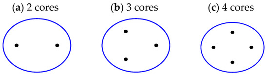
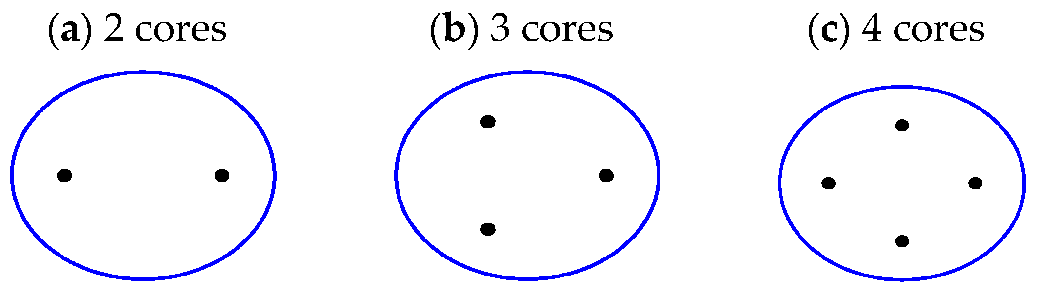
Figure 1.
Cross sections of MCFs with (a) 2 cores, (b) 3 cores and (c) 4 cores. The cores are presented by the black dots.
In this case, the integral in Equation (14) should be limited to integer number of periods. In this case, using Equation (9.1.18) of Ref. [34], the transmission coefficient at the end of a fiber of length reads
In the regime where , this transmission has a harmonic nature. Using Equation (9.2.1) of Ref. [34]
which yields a quantized suppression criterion
Therefore, for any fiber of length for any integer , the crosstalk is suppressed. It should be stressed that this condition is independent of the CP.
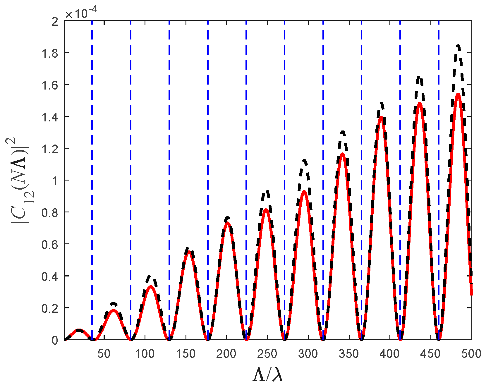
Figure 2 shows the transmission coefficient as a function of the ratio between the period and the optical wavelength for periods. As observed, the approximate expression (17) aligns closely with the exact numerical solution. Furthermore, the crosstalk suppression criterion (19) exhibits strong agreement with both the analytical and numerical results.

Figure 2.
Transmission coefficient as a function of the period for periods. The solid (red) curve represents the exact numerical solution, while the dashed (black) curve represents the analytical approximation (17). The vertical dashed lines represent the solutions of (19). The simulation was taken for the parameters , , and .
Although this formula is strictly valid only for two cores, it can still be applied to more complex structures. Two such cases are presented in Figure 3.

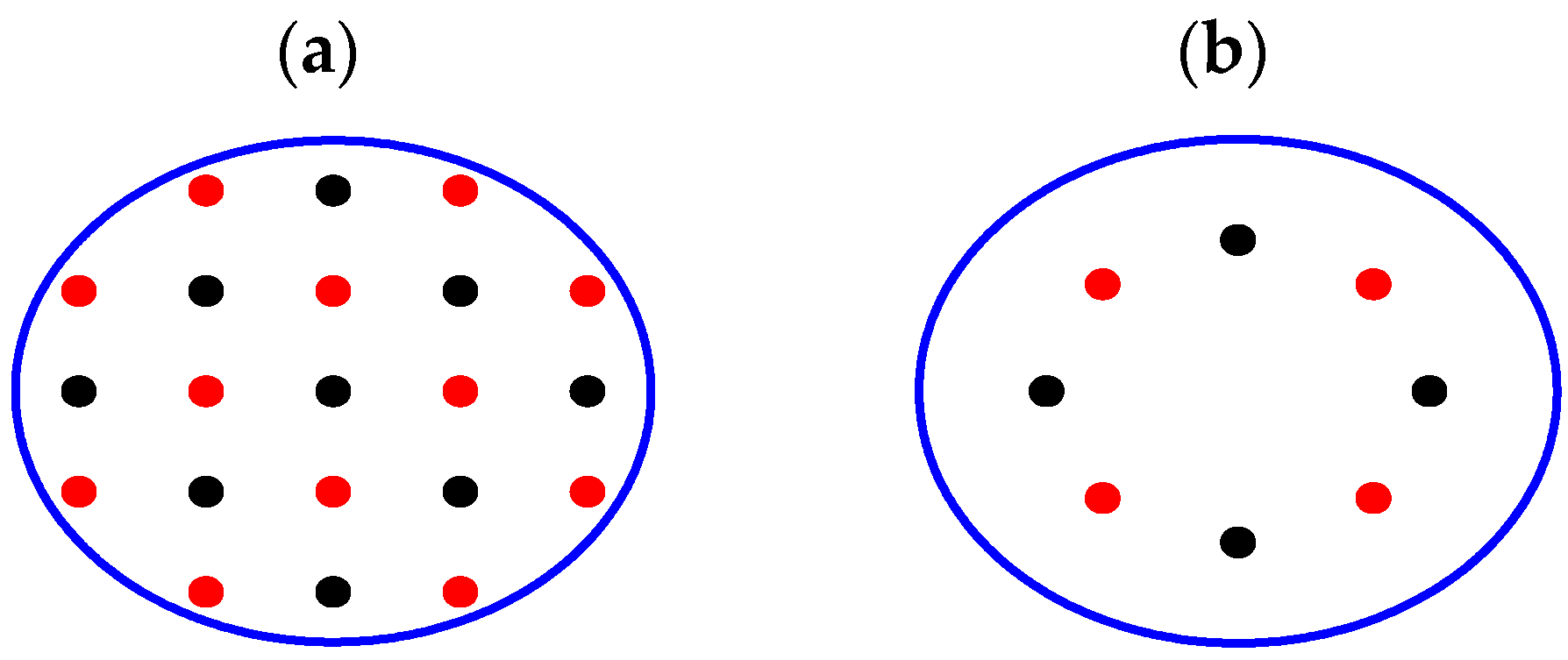
Figure 3.
Two configurations of multi-core fibers, each of which consists of two types of fiber cores (represented by different colors): (a) Rectangular lattice, (b) Circular lattice.
In both cases, the conclusions are entirely generic, regardless of the specific core layout, since the cores’ transverse properties affect only the coupling coefficient . This holds as long as each core type (referring to cores with different refractive index modulation profiles, according to Equation (16)), represented by a different color, designates a distinct phase, i.e., (black) or (red).
Figure 3a shows a rectangular lattice. This approach will reduce crosstalk between adjacent cores to nearly zero. The issue of crosstalk between second-order neighboring cores, i.e., indirect crosstalk, remains, but it is significantly mitigated since crosstalk decreases exponentially with the CP. When the cores are arranged in a rectangular lattice (Figure 3a), this method increases the effective CP by a factor of .
Since the modulation can be incorporated in heterogeneous fibers, then compared to a standard weakly coupled heterogeneous MCF, this fiber can accommodate twice as many cores for the same level of crosstalk and the same fiber diameter.
If the cores are arranged along the circumference of a circle (Figure 3b), the CP can increase by nearly a factor of , where is the (even) number of cores. Similarly, if the refractive index modulation will be implemented in heterogeneous fibers with the same geometry, then this fiber can accommodate twice as many cores for the same level of crosstalk and the same fiber diameter.
Since the suppression criterion is symmetric with respect to the propagation direction, it is applicable also to a bidirectional transmission scenario.
Equation (18) has an important implication. The minima can be very wide. In fact, if was chosen to eliminate crosstalk for wavelength , then, according to (18), at the vicinity of the minima . Therefore, in case the fiber should suppress several wavelength, there is an incentive to choose small . To suppress the entire optical C-band, i.e., , one can choose , for which case, even if then can be as small as .
5. Three-Cores Fiber
When there are three cores, and they are distributed in a equilateral triangle, then
Since the distances between two adjacent cores is the same (see Figure 1b)
In this case, it is easy to see that
The amplitude of the difference in all three cases is the same , and therefore, the criterion for zero crosstalk can be achieved by replacing with in (17) giving
and (19) turns into
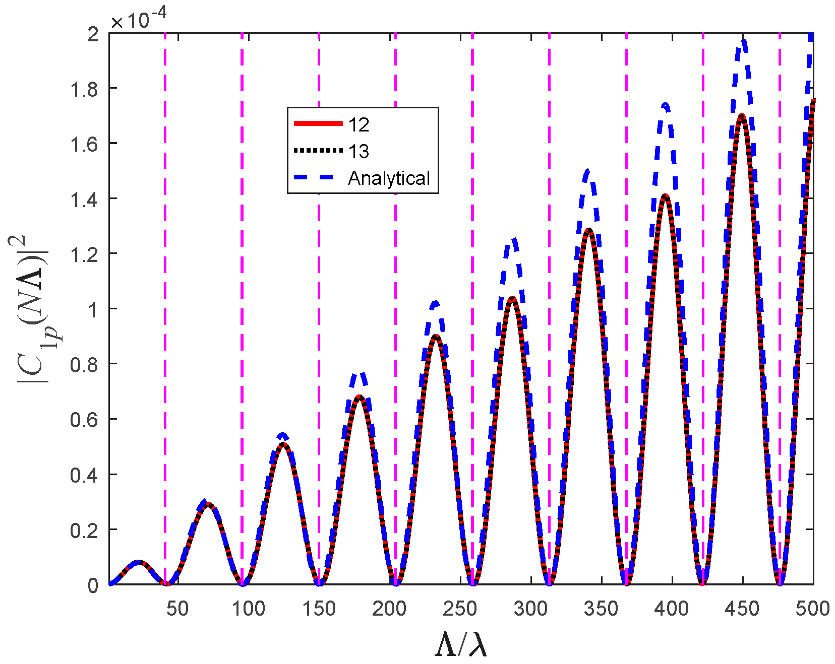
As can be seen in Figure 4, not only do , but they both can be approximated (especially at the minima) by the analytical expression (23).
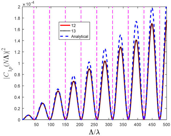
Figure 4.
Numerical solution of the transmission coefficients from the 1st core to the p = 2 (solid red curve) and 3 (dotted black) neighboring cores and the analytical approximation (23) (dashed blue). The vertical dashed lines represent the solutions of (24). The simulation’s parameters were , ,and .
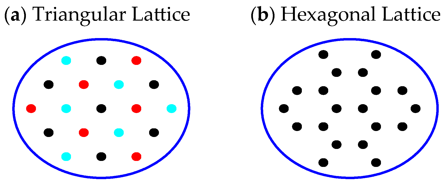
This criterion can eliminate crosstalk in 3-core fiber whenever the fiber length for any integer . However, it can be applied even for other cases, such as triangular lattices (see Figure 5a). The different colors represent cores with different profile phases, i.e., according to (21). Consequently, there are no adjacent cores with the same profile phases, and therefore the effective CP, i.e., identical profile phases, is increased by a factor of , therefore reducing the crosstalk substantially.
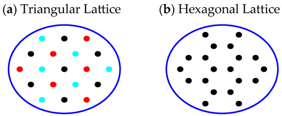
Figure 5.
Triangular and Hexagonal layouts of cores in the fiber. The three types of cores are represented by three different colors.
By incorporating modulation into heterogeneous fibers, this design can support three times as many cores as a standard weakly coupled heterogeneous MCF with the same geometry, all while maintaining the same level of crosstalk and fiber diameter.
6. Four-Cores Fiber and Beyond
In the three-core case, the differences in refractive indexes were the same between all cores. However, when the number of cores is and the changes in the refractive index of two cores (p and q) are
then the relative change is still harmonic
but with an amplitude
whose absolute value cannot be independent of p and q provided Q = 2,3.
In particular, when Q = 4
Consequently, two criterions must hold simultaneously
for integers and .
Criterions (29) and (30) require that
which cannot hold, since is not a rational number. Therefore (29) and (30) cannot be valid simultaneously.
However, because the minima are spectrally broad, significant suppression can still occur even when these criteria are only approximately met, as illustrated in Figure 6. In this figure, the transmission coefficient from the 1st core to the 2nd, 3rd, and 4th cores is plotted. As expected, the transmission to the 2nd and 4th cores coincides, while the transmission to the 3rd core follows a different pattern. Nevertheless, the figure reveals two values of the ratio where all transmission coefficients are low. For fibers with lengths chosen accordingly, crosstalk can be significantly suppressed.
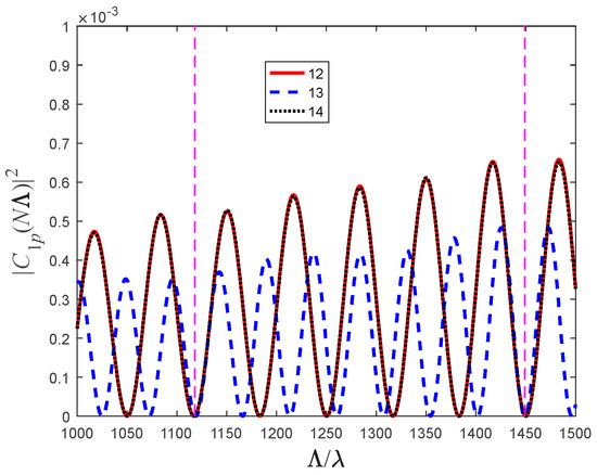
Figure 6.
Numerical solution of the transmission coefficients from the 1st core to the p = 2 (solid red curve), 3 (dashed blue curve) and 4 (dotted black curve) neighboring cores. The vertical dashed lines represent the solutions where all coefficients are bear zero. The same parameters were used as for Figure 4 but now for 4 cores.
This method can be generalized for MCFs with a higher number of cores. The four-core case is particularly important because when these conditions are approximately met, not only is crosstalk substantially reduced in a four-core fiber, but also in hexagonal core structures. In such a configuration, each core has only three nearest neighbors, as shown in Figure 5b. When suppression between these four cores is achieved, the effective distance between identical cores is effectively doubled. Since crosstalk depends exponentially on the effective distance between cores, a significant reduction in crosstalk should occur.
7. Fabrication Considerations
The optimal methods for fabricating these fibers require further detailed research. However, in principle, Bragg grating technology can be utilized, involving a gradual modification of the refractive index through UV light exposure. Since UV illumination can be applied transversely, the fabrication process can be fully automated (see, for example, Refs. [35,36,37,38]). The original technique was optimized for short gratings, as Bragg gratings do not need to be long. However, as explained in previous sections, the modulation wavelength can be significantly longer than the optical wavelength. This allows the method to be scaled for longer fibers. Additionally, since it does not rely on interference at the optical wavelength scale, the UV illumination and grating generation process can be accelerated. Therefore, the UV illumination can take place while the fiber is wrapped around the spinning fiber spool during fabrication. Additionally, multiple fiber cores can be illuminated simultaneously using either separate beams or a tunable mask. Initially, this technology is expected to be expensive due to the development of new fabrication equipment. However, as the technology matures, production costs could approach those of standard fiber manufacturing.
Regarding the robustness of the structure (and its manufacturing), it is important to highlight two key parameters. For suppression to occur, as indicated by Equation (19), the ratio between the harmonic profile wavelength and the optical wavelength must satisfy a specific condition, , and the fiber length must be an integer multiple of , i.e., . Since the suppression effect is independent of the exact choice of (as long as these conditions are met), can be selected to be relatively small (e.g., ~1 mm). This makes the suppression condition robust against thermal variations and manufacturing fluctuations. Specifically, since the thermal expansion of silica glass is , then even a thermal fluctuation of 10 K will cause the to expand by mere 0.5 nm, which is totally negligible in comparison to the optical wavelength.
Furthermore, because is small, even if the fiber length does not precisely meet the condition , the resulting residual crosstalk is negligible compared to the total fiber length. For example, instead of experiencing crosstalk over the entire 10 km length of the fiber, the crosstalk would correspond to less than 1 mm of the fiber. Thus, this structure is highly robust and well-suited for practical implementation.
8. Conclusions and Summary
The crosstalk between adjacent cores in multi-core fibers (MCF), where the refractive index is modulated, is investigated. The crosstalk between two adjacent fiber cores was calculated in the weak crosstalk regime. A general analytical expression was derived for the condition of zero crosstalk. This expression provides a straightforward criterion for the suppression of crosstalk between two, and even three, adjacent cores, resulting in complete suppression in these scenarios. Additionally, it is shown that these criteria can be applied to fibers with more than three modes.
This approach can be used to either identify specific conditions for crosstalk suppression among multiple cores or to arrange the cores in a lattice that suppresses crosstalk only between adjacent cores, thereby significantly reducing overall crosstalk.
By integrating modulation into heterogeneous fibers, the proposed design shows that it can support three times more cores than a standard weakly coupled heterogeneous MCF with the same geometry, while maintaining the same crosstalk levels and fiber diameter.
Additionally, because the modulation profile wavelength can be as short as a millimeter, the crosstalk suppression criterion is highly robust against mechanical and thermal fluctuations, making it well-suited for practical applications.
Funding
This research received no external funding.
Data Availability Statement
The original contributions presented in the study (numerical analysis is included) are included in the article. The numerical parameters are specified under the figures. Further inquiries can be directed to the corresponding author.
Conflicts of Interest
The author declares no conflict of interest.
References
- Puttnam, B.J.; Rademacher, G.; Luís, R.S. Space-division multiplexing for optical fiber communications. Optica 2021, 8, 1186–1203. [Google Scholar] [CrossRef]
- Zhu, B.; Taunay, T.F.; Yan, M.F.; Fishteyn, M.; Oulundsen, G.; Vaidya, D. 70-Gb/s Multicore Multimode Fiber Transmissions for Optical Data Links. IEEE Photon. Technol. Lett. 2010, 22, 1647–1649. [Google Scholar] [CrossRef]
- Richardson, D.J.; Fini, J.M.; Nelson, L.E. Space-division multiplexing in optical fibres. Nat. Photon. 2013, 7, 354–362. [Google Scholar] [CrossRef]
- Li, G.; Bai, N.; Zhao, N.; Xia, C. Space-division multiplexing: The next frontier in optical communication. Adv. Opt. Photon. 2014, 6, 413–487. [Google Scholar] [CrossRef]
- Soma, D.; Wakayama, Y.; Beppu, S.; Sumita, S.; Tsuritani, T.; Hayashi, T. 10.16 Peta-bit/s Dense SDM/WDM transmission over Low-DMD 6-Mode 19-Core Fibre Across C+L Band. In Proceedings of the 2017 European Conference on Optical Communication (ECOC), Gothenburg, Sweden, 17–21 September 2017; pp. 1–3. [Google Scholar] [CrossRef]
- Klaus, W.; Winzer, P.J.; Nakajima, K. The Role of Parallelism in the Evolution of Optical Fiber Communication Systems. Proc. IEEE 2022, 110, 1619–1654. [Google Scholar] [CrossRef]
- Ohashi, M.; Matsuo, S.; Hayashi, T.; Imamura, K.; Kokubun, Y.; Koshiba, M.; Mori, T.; Nakajima, K.; Nakazawa, M.; Saitoh, K.; et al. Optical Fibers for Space-Division Multiplexing; Optical Sciences Book Series; Nakazawa, M., Suzuki, M., Awaji, Y., Morioka, T., Eds.; Springer: Berlin/Heidelberg, Germany, 2022; Volume 236, Chapter 2. [Google Scholar]
- Kashima, N. Passive Optical Componenets for Optical Fiber Transmission; Artech House: Norwood, MA, USA, 1995. [Google Scholar]
- Anis, M.I.; Ali, H. Multi-Core Fiber Technology from Fiber Optics—Technology and Applications; Huerta-Cuellar, G., Ed.; IntechOpen: London, UK, 2021. [Google Scholar]
- Singh, K.; Kaur, G. Multi-Core Fibers: An Overview. In Proceedings of the International Conference on Emerging Technologies in Electronics & Communication (ICETEC-13), Amritsar, India, 20–22 December 2013; Volume 1. [Google Scholar]
- Koshiba, M.; Saitoh, K.; Kokubun, Y. Heterogeneous multi-core fibers: Proposal and design principle. IEICE Electron. Express 2009, 6, 98–103. [Google Scholar] [CrossRef]
- Eriksson, T.A.; Puttnam, B.J.; Luís, R.S.; Karlsson, M.; Andrekson, P.A.; Awaji, Y.; Wada, N. Experimental Investigation of Crosstalk Penalties in Multicore Fiber Transmission Systems. IEEE Photon. J. 2015, 7, 7200507. [Google Scholar] [CrossRef]
- Li, Y.; Wang, X.; Zheng, H.; Li, X.; Bai, C.; Hu, W.; Liu, Y.; Dong, Q. A novel six-core few-mode fiber with low loss and low crosstalk. Opt. Fiber Technol. 2020, 57, 10221. [Google Scholar] [CrossRef]
- Mu, X.; Ottino, A.; Ferreira, F.M.; Zervas, G. Optimization of 125-µm Heterogeneous Multi-Core Fibres Design using AI. IEEE J. Sel. Top. Quantum Electron. 2022, 28, 4300113. [Google Scholar] [CrossRef]
- Mu, X.; Ottino, A.; Ferreira, F.M.; Zervas, G. Design and transmission analysis of trench-assisted multi-core fibre in standard cladding diameter. Opt. Express 2022, 30, 38152. [Google Scholar] [CrossRef]
- Shao, P.; Li, S.; Meng, X.; Guo, Y.; Wang, L.; Li, Z.; Ma, L.; Li, J.; Cheng, T.; Xu, W.; et al. Low crosstalk and large effective mode field area heterogeneous 13-core 6-mode fiber with double high refractive index rings. Opt. Commun. 2023, 530, 129136. [Google Scholar] [CrossRef]
- Hayashi, T.; Sakamoto, T.; Yamada, Y.; Ryf, R.; Essiambre, R.-J.; Fontaine, N.; Mazur, M.; Chen, H.; Hasegawa, T. Randomly-Coupled Multi-Core Fiber Technology. Proc. IEEE 2022, 110, 1786–1803. [Google Scholar] [CrossRef]
- Rademacher, G.; van den Hout, M.; Luís, R.S.; Puttnam, B.J.; Di Sciullo, G.; Hayashi, T.; Inoue, A.; Nagashima, T.; Gross, S.; Ross-Adams, A.; et al. Randomly Coupled 19-Core Multi-Core Fiber with Standard Cladding Diameter. In Proceedings of the Optical Fiber Communication Conference (OFC), San Diego, CA, USA, 5–9 March 2023; p. Th4A.4. [Google Scholar]
- Sun, L.; Zhang, J.; Zhou, G.; Chen, B.; Liu, G.N.; Cai, Y.; Li, Z.; Lu, C.; Shen, G. Theoretical investigations of weakly- and strongly-coupled multi-core fibers for the applications of optical submarine communications under power and fiber count limits. Opt. Express 2023, 31, 4615–4629. [Google Scholar] [CrossRef] [PubMed]
- Bohm, D. Quantum Theory; Dover Publications: Garden City, NY, USA, 1979. [Google Scholar]
- Vutha, A.C. A simple approach to the Landau–Zener formula. Eur. J. Phys. 2010, 31, 389. [Google Scholar] [CrossRef]
- Wittig, C. The Landau−Zener Formula. J. Phys. Chem. B 2005, 109, 8428–8430. [Google Scholar] [CrossRef] [PubMed]
- Kayanuma, Y. Role of phase coherence in the transition dynamics of a periodically driven two-level system. Phys. Rev. A 1994, 50, 843. [Google Scholar] [CrossRef]
- Kayanuma, Y. Stokes phase and geometrical phase in a driven two-level system. Phys. Rev. A 1997, 55, 2495. [Google Scholar] [CrossRef]
- del Campo, A.; García-Calderón, G.; Muga, J.G. Quantum transients. Phys. Rep. 2009, 476, 1–50. [Google Scholar] [CrossRef]
- Bagwell, P.F.; Lake, R.K. Resonances in transmission through an oscillating barrier. Phys. Rev. B 1992, 46, 15329. [Google Scholar] [CrossRef]
- Azbel, M.Y. Elevator resonance activation. Europhys. Lett. 1992, 18, 537. [Google Scholar] [CrossRef]
- Azbel, M.Y. Eigenstate Assisted Activation. Phys. Rev. Lett. 1992, 68, 98. [Google Scholar] [CrossRef] [PubMed]
- Granot, E. Selected elevation in quantum tunneling. Europhys. Lett. 2003, 61, 817. [Google Scholar] [CrossRef]
- Granot, E.; Zangwill, G. Generic temporal quantization criterion in Dynamic Resonant Tunneling for Current Suppression. Phys. B Condens. Matter 2023, 669, 415332. [Google Scholar] [CrossRef]
- Mandel, L.; Wolf, E. Optical Coherence and Quantum Optics; Cambridge University Press: Cambridge, UK, 1995. [Google Scholar]
- Granot, E. Total Reflection of Optical Beams by Weakly Oscillating Dielectric Scatterers. Phys. Rev. A 2016, 94, 063828. [Google Scholar] [CrossRef]
- Granot, E. Derivation of analytical expressions for anomalous reflection in the limit of zero thickness and weakly modulated dielectric grating. J. Opt. Soc. Am. A 2022, 39, 2205–2213. [Google Scholar] [CrossRef]
- Abramowitz, M.; Stegun, A. Handbook of Mathematical Functions; Dover Publications: Garden City, NY, USA, 1965. [Google Scholar]
- Delmdahl, R.; Buchwald, K. Optics Fabrication: Fiber Bragg Grating Fabrication System Is Automated; Laser Focus World: Nashua, NH, USA, 2016; pp. 31–34. [Google Scholar]
- Stepanov, D.Y.; Corena, L. Bragg grating fabrication with wide range coarse and fine wavelength control. Opt. Express 2014, 22, 27309–27320. [Google Scholar] [CrossRef]
- Othonos, A.; Kalli, K. Fiber Bragg Grating Fundamentals and Applications in Telecommunications and Sensing; Artech House: Boston, MA, USA, 1999. [Google Scholar]
- Kashyup, R. Fiber Bragg Gratings; Academic Press: San Diego, CA, USA, 1999. [Google Scholar]

Disclaimer/Publisher’s Note: The statements, opinions and data contained in all publications are solely those of the individual author(s) and contributor(s) and not of MDPI and/or the editor(s). MDPI and/or the editor(s) disclaim responsibility for any injury to people or property resulting from any ideas, methods, instructions or products referred to in the content. |
© 2025 by the author. Licensee MDPI, Basel, Switzerland. This article is an open access article distributed under the terms and conditions of the Creative Commons Attribution (CC BY) license (https://creativecommons.org/licenses/by/4.0/).